Trekkrunner HG-187F Quick setup guide

NOTE:
Please read all instructions
carefully before using this
product
Contents
Important Precautions
Component - Parts
Components - Fixings
Assembly
Operation and Adjustment
Maintenance
Parts List
Model
HG-187F
Retain This
Manual for
Reference
190725
OWNER'S
MANUAL
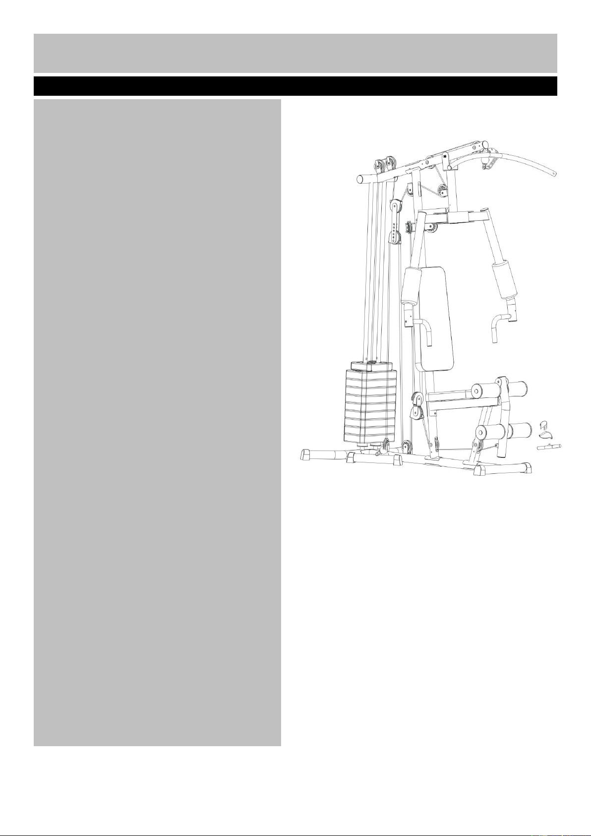
HG-187F Home Gym
Assembly and Use Instructions
1
1
Contents
Safety Information
2
Components –Fixings
3-4
Assembly Instructions
5-22
Exercising Information
23-26
Before starting to exercise
23
Muscle chart
24
Warming up and cooling down
Exercises
25-26
Care and Maintenance
27
Exploded Parts List
28-29
1

To reduce the risk of serious injury, read the entire manual before you assemble or use your home gym.
In particular, note the following safety precautions.
Assembly
•Check you have all the components and tools
listed in the parts list, bearing in mind that, for
ease of assembly, some components are pre-
assembled.
•Keep children and animals away from the
exercise area, small parts could pose a choking
hazard if swallowed.
•Make sure you have enough space to layout the
parts before starting.
•Assemble the item as close to its final position
(in the same room) as possible.
•The product must be installed on a stable and
level surface.
•Dispose of all packaging carefully and responsibly.
Using
•Keep unsupervised children away from the
equipment.
•Injuries to health may result from incorrect or
excessive training.
• If any of the adjustment devices are left
projecting, they could interfere with the user’s
movement.
•It is the responsibility of the owner to ensure that
all users of this product are properly informed as to
how to use this product safely.
•This product is intended for domestic use only.
Do not use in any commercial, rental, or institutional
setting.
•Before using the equipment to exercise, always
perform stretching exercises to properly warm up.
•If the user experiences dizziness, nausea, chest
pain, or other abnormal symptoms stop the
workout and seek immediate medical attention.
•Only one person at atime should use the
equipment.
•Keep hands away from all moving parts.
•Always wear appropriate workout clothing when
exercising. Do not wear loose or baggy clothing,
as it may get caught in the equipment. Wear
trainers to protect your feet while exercising.
•Do not place any sharp objects around
the equipment.
•Disabled persons should not use the equipment
without aqualified person or doctor in
attendance.
• Keep this equipment indoors, away from
moisture and dust. Do not put the equipment in a
garage, outbuilding, covered patio, or near water.
• If children are allowed to use the equipment under
supervision, their mental and physical development
should be taken into account. They should be
controlled and instructed to the correct use of the
equipment. The equipment is under no
circumstances suitable as a toy.
•This product is suitable for a maximum user
weight of: 120 kgs.
•This product is not suitable for therapeutic
purposes.
•Free area shall be not less than 0.6m greater than
the training area in the directions from which the
equipment is accessed. The free area must also
include the area for emergency dismount. Where
equipment is positioned adjacent to each other the
value of the free area may be shared. Keep
unsupervised children away from the equipment.
Warning: Parents and others in charge of children
should be aware of their responsibility because the
natural play instinct and the fondness of
experimenting of children can lead to situations and
behavior for which the training equipment is not
intended.
Warning: Before beginning any exercise programme, consult your doctor. This is especially
important for individuals over the age of 35 or persons with pre-existing health problems. You
MUST read all instructions before using any fitness equipment.
Safety Information
2
Important –Please read fully before assembly or use
his exercise equipment is built for optimum safety. However, certain
precautions apply whenever you operate a piece of exercise equipment. Be
sure to read the entire manual before you assemble, operate or use this
equipment. In particular, note the following safety precautioortant –Please
read fully before assembly or use

Note: Some of thesmaller components may be pre-fitted to thelarger components. Please check carefully
before contacting us regarding anymissing components. Please prepare an adjustable spanner by
yourself when you are intend to assemble this machine.
Components - Fixings
Please check you have all fixings listed below
3

4
Components - Fixings
Please check you have all fixings listed below

Assembly instructions
Step 1
Attach the main base frame (3) to
the rear stabilizer(4), Carefully
align the holes and secure them
with 2pcs M10*70 Carriage
bolt(61), one pc U-shape bracket
(12), 2pcs φ10 wahsers(70) and
2pcs M10 aircraft nuts(74).
.
5
Step 2
(A) Insert the 2pcs guide rods (17)
into the holes of the rear
stabilizer(4),Secure them with
2pcs φ10 wahsers(70) and
2pcs M10*25 Allen bolts(65).
(B) Place 2pcs rubber bumper(38)
along the guide rod from the top
to the bottom.
.

Attach the front vertical frame (2) onto the main base frame(3) , carefully align the holes and secure
them with 2 pcs M10×70 carriage bolts(61), one pc curve bracket (20), 2pcs Ø10 washers (70) and 2 pcs
M10 Aircraft nuts (74).
Assembly instructions
Step 3
6

7
Assembly instructions
(A) Slide the 10pcs weight plate(33) along the guide rods (17) from the top to the bottom.insert the
selector rod (19) into the hole of weight plates. and then place the selector stem (32) onto the
selector rod (19)
Make sure that all the grooves face back and backwards.
(B) Insert the selector pin (29) into the hole and select the desired weight when exercising.
.
Step 4
Make sure all the grooves face back and
downwards

Assembly instructions
Place the upper frame (1) onto the front vertical frame (2) and 2 pcs guide rods(17), Carefully align the
holes and secure them with 2pcs M10*25 Allen bolt (65), 2pcs Ø10 washers (70). 2pcs M10*70 Crriage
bolts(61), one pc curve bracket(20), 2pcsØ10 washers (70) and 2pcs M10 aircraft nuts(74).
Step 5
8
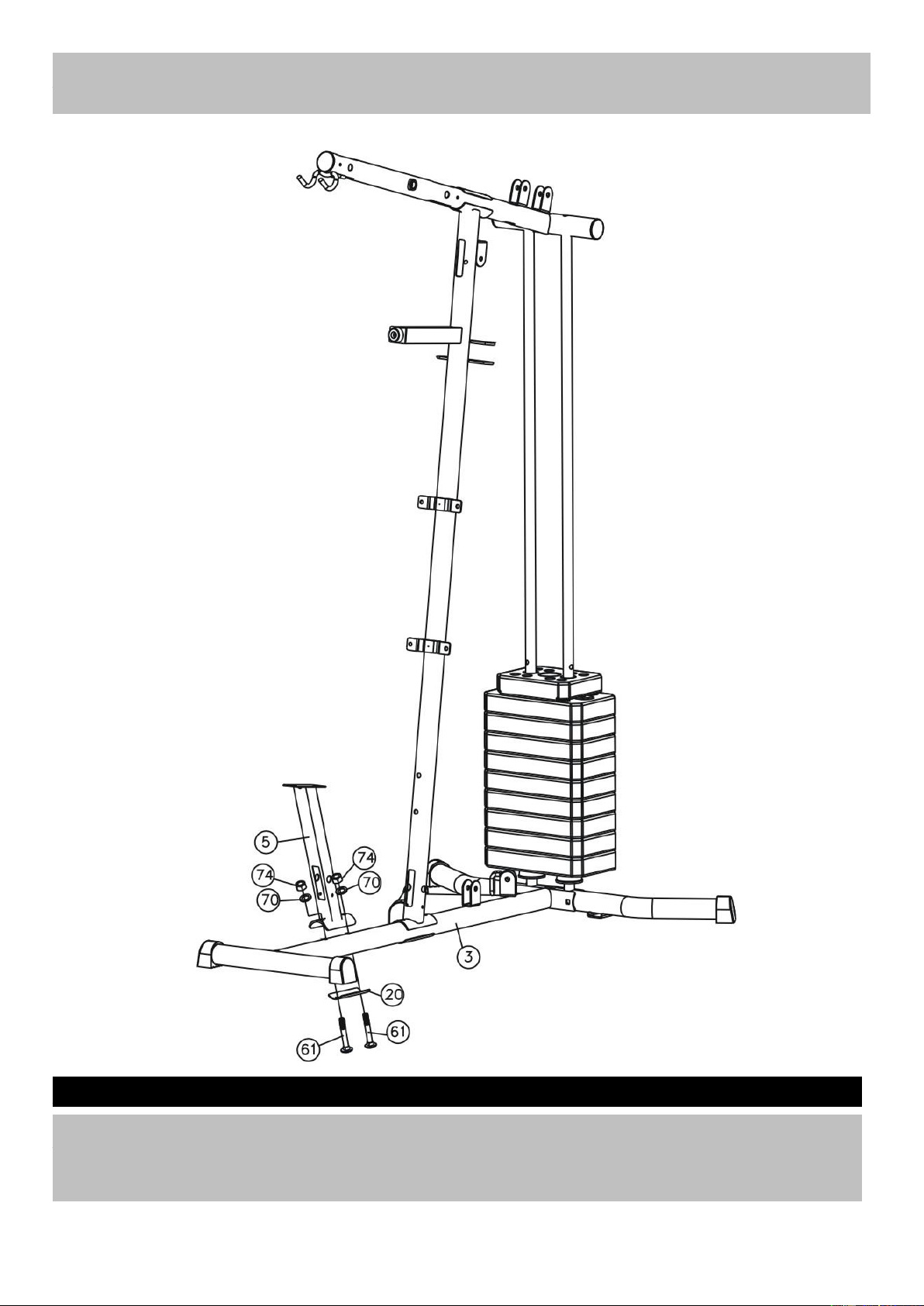
Attach the slant support (5) onto the main base frame (3), Carefully align the holes and secure them with
2pcs M10*70 Carriage bolt(61), one pc curve bracket(20), 2pcsØ10 washers (70) and 2pcs M10 aircraft
nuts(74).
Step 6
Assembly instructions
9

(A) Attach the sest pad support (6) onto the slant support (5), Carefully align the holes and secure them
with 2 pcs M10*20 Allen bolt(66) and2pcsØ10 washers (70) .
(B) Attach the another end of the seat pad support (6) to the front vertical frame, Carefully align the holes
and secure them with 2pcs M10*70 Carriage bolt(61), one pc curve bracket(20), 2pcsØ10 washers
(70) and 2pcs M10 aircraft nuts(74).
Step 7
Assembly instructions
10

Attach the front press base(8) to the upper frame(1)as the diagram shows,Carefully align the holes
and secure them with 2pcs M10 aircraft nuts(74), 2pcsØ10 washers (73) and one pc front press
axle(36)
Assembly instructions
11
Step 8
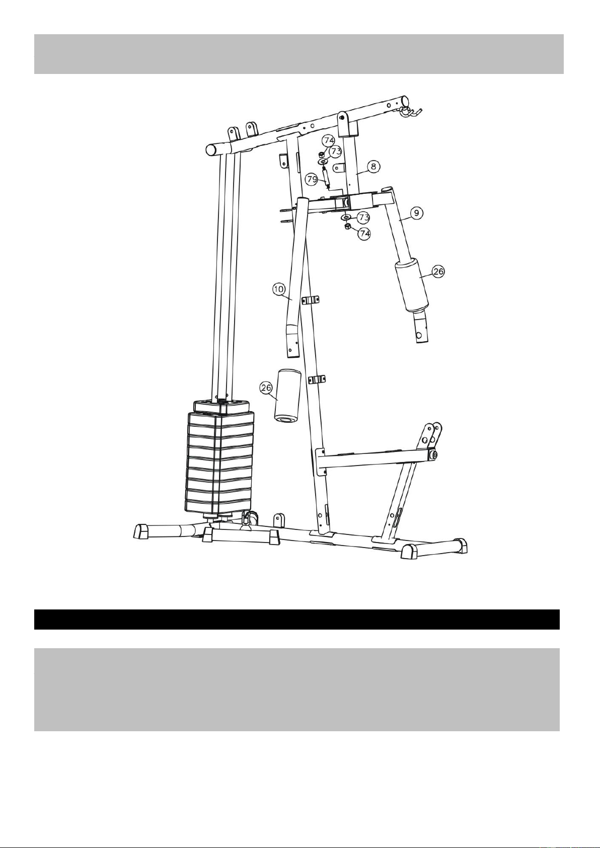
Assembly instructions
(A). Attach the right butterfly frame (10) to the front press base and secure them with one pc axle(79),
2pcs M10 aircraft nuts(74), 2pcsØ10 washers (73).Push one pc butterfly foam roll(26) from the
bottom of the right butterfly frame to the middle.
(B) Install the left butterfly frame with the same method.
Step 9
12

(A) Attach the handle (11) to the right butterfly frame , Secure them with one pc M10*20 Allenbolt(66),
one pc M10*60 Allen bolt(68) and 2 pcs φ10 washer(70).
(B) Install another handle with the same method.
Step 10
Assembly instructions
13

(A) Attach the backrest pad (24) to front vertical frame , Carefully align the holes and secure them with
4 pcs M8*16 Allen bolt (67) and 4 pcs Ø8 washers (71) .
(B) Place the seat pad (25) onto the seat pad support, Sucure them with 4 pcs M8*16 Allen bolt (67) and
4 pcs Ø8 washers (71) .
Assembly instructions
14
Step 11

Attach the leg developer(7) to the bracket of the seat pad support(6), secure them with one pc
M12*80 Allen bolt (60), 2 pcs φ12 washer(72) and one pc M12 aircraft nut(75)
Step 12
Assembly instructions
15

Assembly instructions
16
Step 13
Attach the 2pcs foam roll tube (23) into the holes halfway as the diagram shows. And then push the
4pcs foam roll (27) from both end seperately.
Step 14
Attach the swivel pulley bracket (14) as the diagram shows and secure them with one pc M10*65 Allen
bolt(62), 2pcs φ10 washers (70) and one pc M10 aircraft nut(74). Install another swivel pulley bracket
with the same way.

(A) Attach the upper cable(46) through the front opening of the upper frame,make sure that the ball
stoper should be under the upper frame. Place one pc pulley below the cable and secure it with one
pc M10*65 Allen bolt(62) and one pc M10 aircraft nut(74).
(B) Draw the cable backwards and reach the second opening , Install a pc pully with the same way in A.
(C) Draw the cable around the pulley and reach the bracket of the front press base,Secure the pulley
with one pc M10*40 Allen bolt (64) ,2pcs φ10 washers (70) and one pc M10 aircraft nut(74).
(D) Draw the cable around the pulley and backwards until it reach the opening of frontvertical frame ,
Install one pc pulley with the same way in C.
(E) Draw the cable around the pulley and downwards,Place one pc pulley onto the cable ,Secure the
pulley with 2pcs pulley cover(59),double floating pulley bracket (16) together with the same way in
C.
(F) Draw the cable around the pulley and upwards, Install 2 pcs pulley as the diagram shows with 2 pcs
M10*40 Allen bolt(63),4pcsφ10 washers (70), 2pcs cable retainer(22) and 2 pcs M10 aircraft
nut(74).
(G) Draw the cable around the pulley and go through the hole , Thread the end of upper cable to the top
of the selector rod.
Assembly instructions
17
Step 15
17

Assembly instructions
Step 16
(A) Attach one end of the butterfly cable(47) to the bracket as the diagram shows. Place the cable
onto the pulley and secure the pulley with one pc M10*40 Allen bolt(64), 2pcsφ10 washers (70) and
one pc M10 aircraft nut(74).
(B) Draw the cable downwards , place one pc pulley onto the cable ,Secure the pulley, 2pcs pulley
cover(59), cross doubel floating pulley bracket(15) together with the same way in A.
(C) Draw the cable upwards and repeat the above the method to install another end of the butterfly
cable.
18

Assembly instructions
19
Table of contents
Other Trekkrunner Home Gym manuals


