TRENCHERPRO 26-183 User manual

TRENCHER PRO
Mini-Trencher
Operator’s Manual
26-183: 16” Trencher
26-184: 20” Trencher
26-185: 27” Trencher
Product registration form attached to the back of this booklet. Mail your registration within 2
weeks of date of purchase.

Parts and Design
Power Head *
* 16” & 20” con gurations sold with
Husqvarna K770 power head; 27” sold
with Husqvarna K970.
Welcome!
Thanks for buying a TrencherPro! We design our products to meet the high demands
of our industrial and commercial clients, with ease-of-use that’s aimed at homeowners
and do-it-yourselfers. That means that our products are tough enough to meet rigorous
industry standards, but designed for non-professionals to learn to use. We warranty all
TrencherPro parts for one year from purchase date. Register your product today.
If you have feedback or questions, we want to know!
Mini-Trencher
TRENCHER PRO
This user guide/manual covers assembly, use, basic service and troubleshooting information for Tren-
cherPro parts (“digging-head drive adaptor”), including:
• mounting and installing the digging chain and chain guard;
• assembling the trenching cart;
• instructions for basic operation.
For more information about use and maintenance of the power head refer to operator’s manual pro-
vided.
WARNING!
WEAR PERSONAL
PROTECTIVE EQUIPMENT
Failure to follow warnings, cautions, or assembly
and operation instructions in this manual may
result in serious injury or death.
Read this operator’s manual before operation!
●Do not permit children to operate this
equipment at any time. Do not permit others
that have not read and understood this
manual to operate the mini-trencher.
●Keep all people and pets a minimum of
10 feet away from the work area when
operating the mini-trencher. Only the
operator should be near the mini-trencher
during use.
●Do not operate this device when under the
inuence of alcohol, drugs or medication.
●Do not allow a person who is tired, not
completely alert, or otherwise impaired to
operate the mini-trencher.
●Always check with authorities for
underground utilities before digging
trenches. Serious injury or death could
result from contact with gas or electric lines.
●Read the power head operation manual
concerning the use and maintenance of
power head.
●Make sure that all safety guards are in
place and securely fastened. Do not operate
if any guards are missing.
●Make sure that the digging chain is
correctly installed, oriented, and in good
working condition prior to use.
We recommend operating this minitrencher with
the cart.
Death or serious injury can result from
entanglement with moving parts.
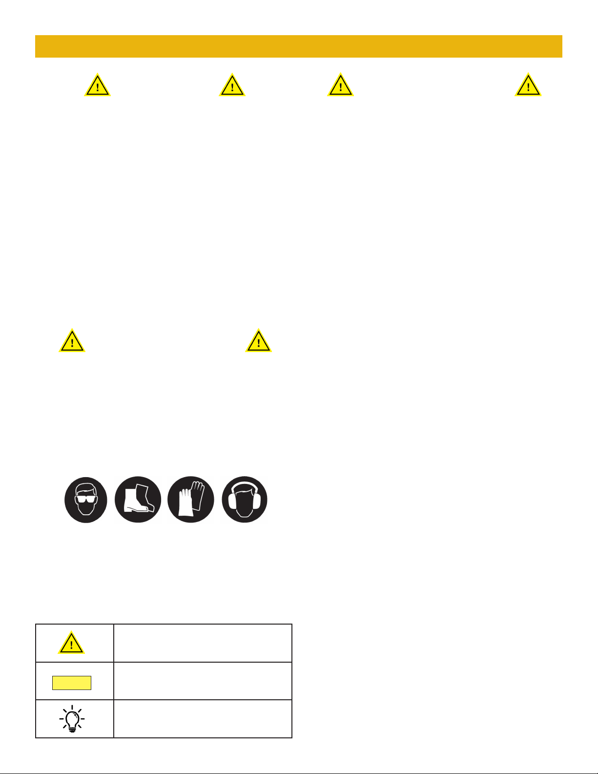
GENERAL SAFETY
KEY TO SYMBOLS
Notice:
Tip
Indicates the possibility of death
or serious injury.
Indicates the possibility of injury
to self or damage to equipment.
Indicates additional information.
3
Important Safety Information
Read and thoroughly understand all instructions
and safety information before assembling or
operating this mini-trencher. Failure to do so
may result in serious injury or death. Do not
allow anyone who has not read this manual to
operate the device. As with all power equipment, a
trencher can be dangerous if assembled or used
improperly. Do not operate if you have doubts or
questions concerning safe operation.
Call our customer service department at 720-
437-7640, or email us at customerservice@
tooltuffdirect.com if you have questions or
concerns about the safe operation of this
equipment.
When operating this minitrencher it is essential
that you wear safety gear including safety
glasses, steel toe shoes, well-tted gloves
(no loose cuffs or draw strings), and hearing
protection. We also recommend a face guard,
especially for hand-held applications.
Do not wear loose clothing or jewelry that can be
caught by moving parts. Keep clothing and hair
away from all moving parts while operating.
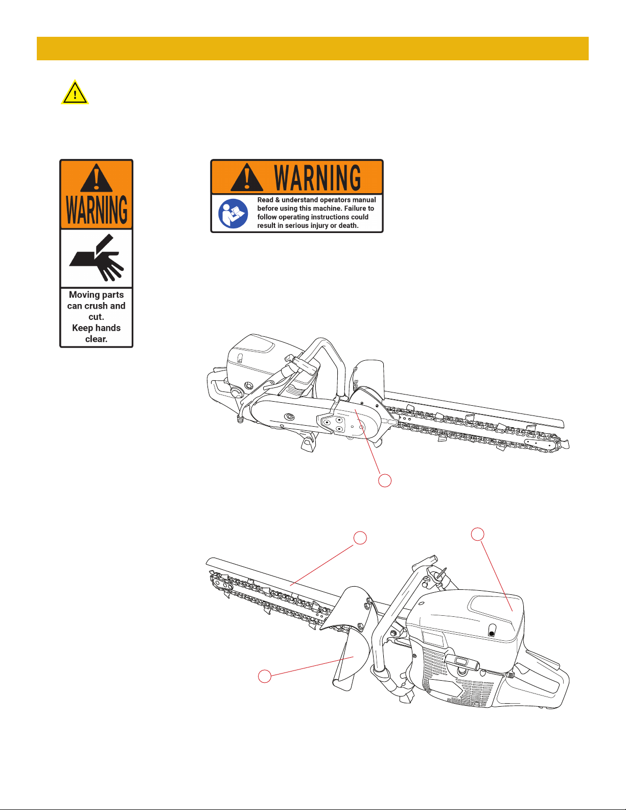
Safety Decals
Make sure all safety warning decals are attached and in readable condition. Replace
missing or defaced decals. Call 720-437-7640 for replacement decals.
1) Part # 29-036
2) Part # 29-037
1
1
1
2
4
Important Safety Information

INTENDED USE REASONABLY FORESEEABLE
MISUSE
5
General Use Guidelines
This device is designed and tested for use
digging narrow (2-3”) trenches from 16-27” in
depth (depending on conguration) in most soil
types. It is not intended to cut solid surfaces
such as tarmac or concrete. Excessively rocky
soil types, soil with large heavy rocks, or soil with
roots measuring more than 2” in diameter can
damage the chain, drive adapter, or powerhead.
It is recommended for laying sprinkler lines,
drainage pipes, cables, root barriers, and related
applications. Do not use the mini-trencher for
any purpose other than digging trenches in the
suitable soil. Any other use is unauthorized and
may result in serious injury or death.
We recommend that you use the cart when
digging trenches. It reduces fatigue and keeps
you at a safe working distance from moving
parts and debris. However, it is possible to use
the trencher without the cart if the situation
demands.
Use common sense and stay safe!
The following constitutes improper use
and voids any warranty:
Notice:
Always check with authorities for
underground utilities before digging
trenches!
Serious injury or death could result from
contact with gas or electric lines.
• Attempting to cut wood or trim hedges
• Attempting to cut concrete, asphalt or tarmac,
or any solid surface
• Attempting to cut solid stone or rock
• Use in extremely rocky soil
In the course of digging a trench, the mini-
trencher may come into contact with unforeseen
objects such as large tree roots, large heavy
rocks, unmarked obstacles, etc. We consider this
reasonably foreseeable misuse and will work with
you to keep your mini-trencher operational.
Please contact our service department at:
customerservice@tooltuffdirect.com
or
720-437-7640
TRENCHER PRO
10
3
1
2
4
5
6
7
8
9
11
12
13
15
14 16
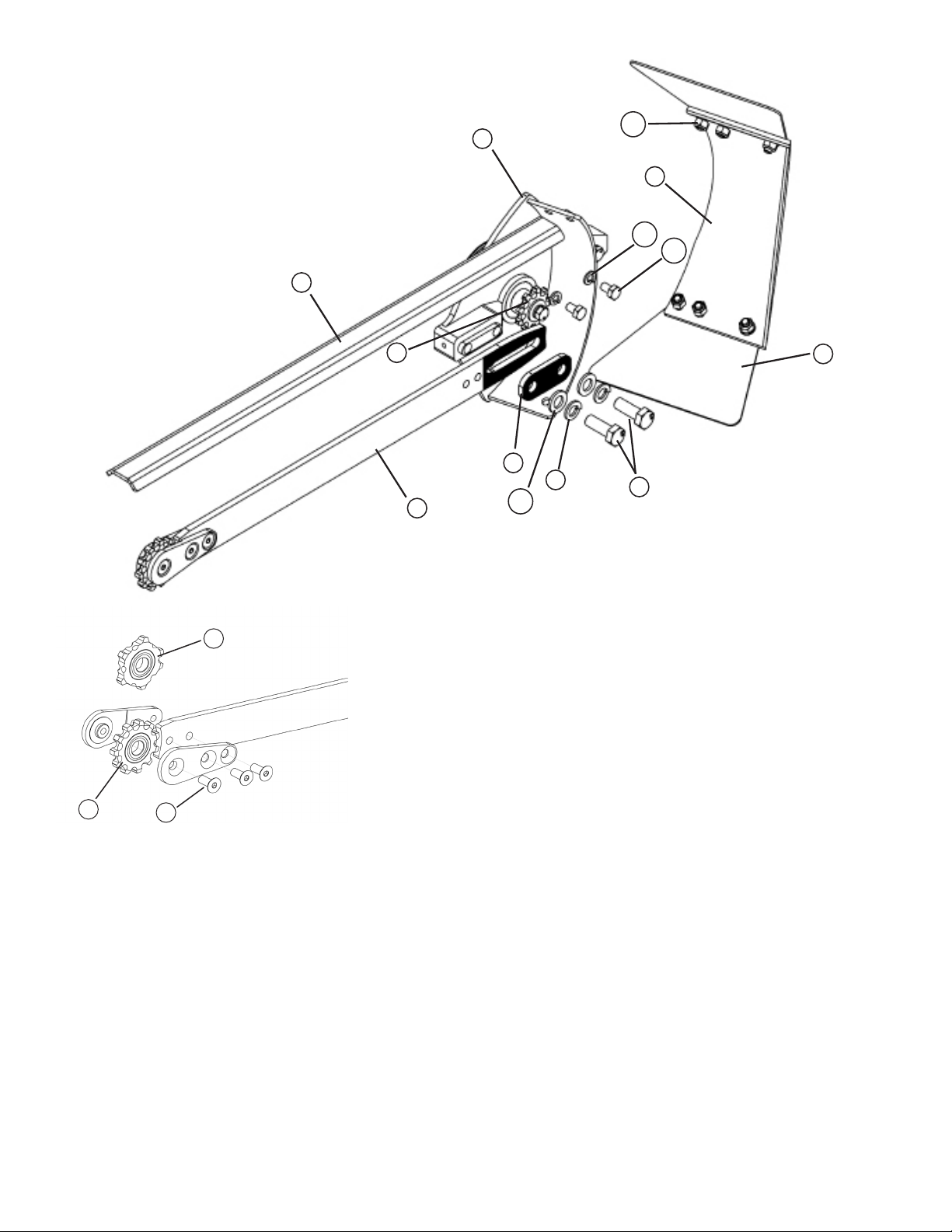
ref. # description part #
1 Main mount 26-114
2 Heavy-duty digging bar 26-115 / 26-179 / 26-180
3 (Chain bar) mounting plate 26-118
4 Chain guard 26-146
5 Drive sprocket 26-140
6 Plastic guard 26-147
7Rubber guard ap (x 2) 26-137
8M12 bolt (x 2); (1.25mm X 35mm)
9M12 lock washer (x 2)
10 M12 washer (x 2)
11 M8 bolt (x 2); (1.25mm X 14mm)
12 M8 lock washer (x 2)
13 M8 nylock nut (x 6)
Inset
14 Nose sprocket A (11 teeth) 26-170
15 Nose sprocket B (6 teeth) 26-120
16 M8 screw (x 3); (1.25mm X 20mm)
6
Mini-Trencher Parts Guide:
Digging-head drive adapter
Tip
Notice:
7
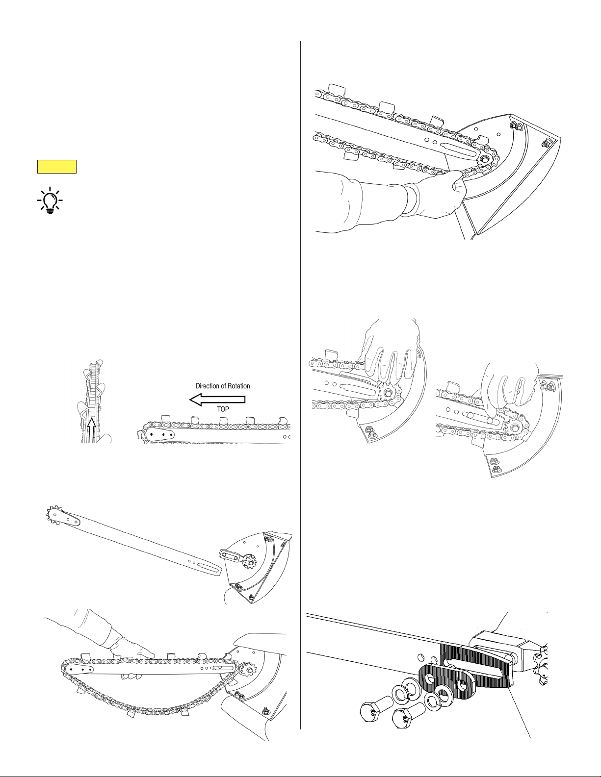
Step 1: Installing the Digging Bar
and Chain
The heavy-duty digging bar [2] and chain are
disassembled for shipping. Before operating the
mini-trencher, you must install the digging bar
and chain, then tension the chain for the type of
material you will be working with.
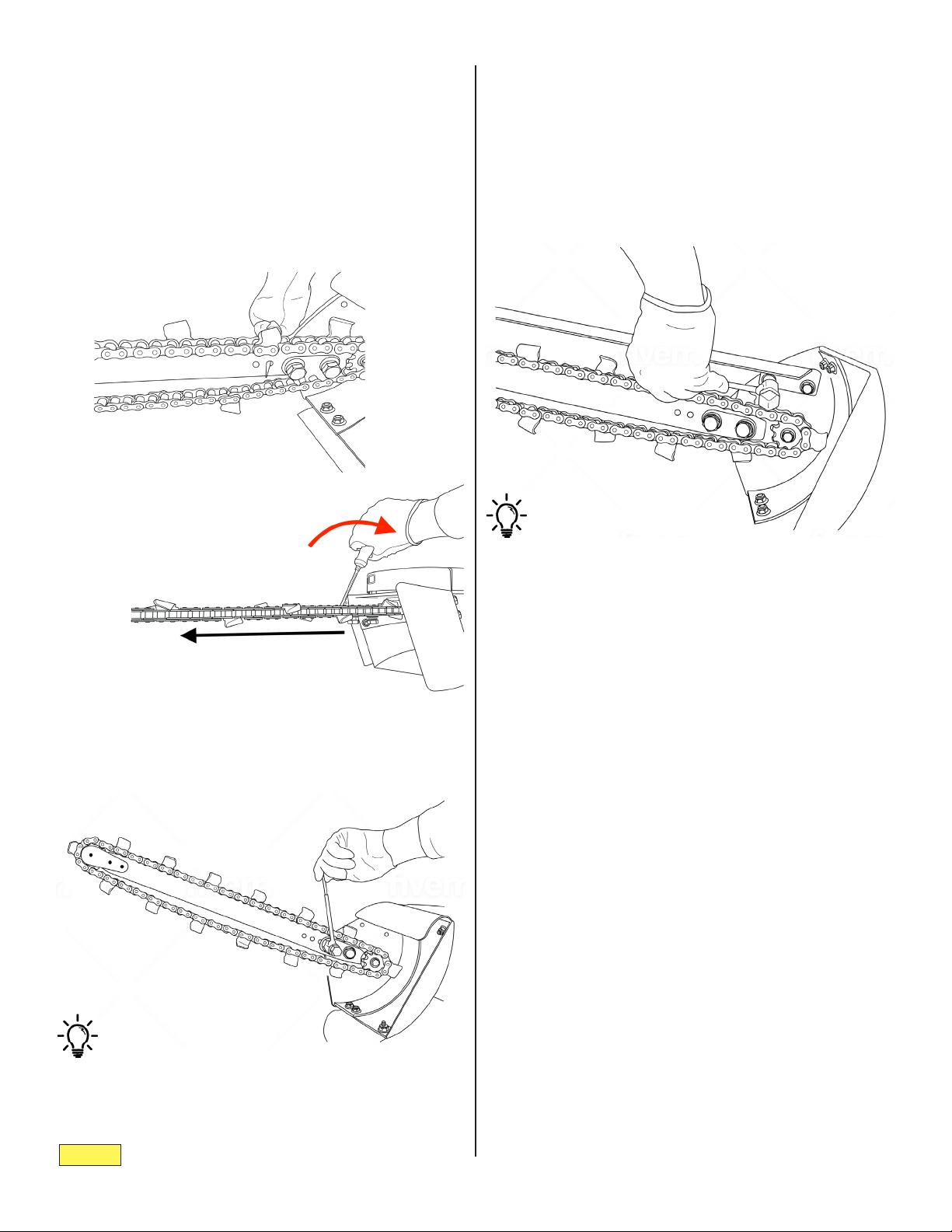
1. Orient the digging chain correctly.
During operation, the chain rotates away from the
powerhead on the top side and returns on the bot-
tom, pulling loose material with it. e chain must be
oriented correctly, with the teeth opening towards the
loose material.
2. Mount the chain and chain bar.
A. Get the bar in position. Drape the digging
chain over the bar.
B. Seat the chain on both the nose sprocket
[14/15] and drive sprocket [5] as you mount
the bar.
C. Slide the slot into place. It should t snugly.
Use the M12 bolts [8], washers [10] and lock washers
[9] to attach the mounting plate [3], and tighten loose-
ly.
• Don’t tighten rmly until you tension the
chain.
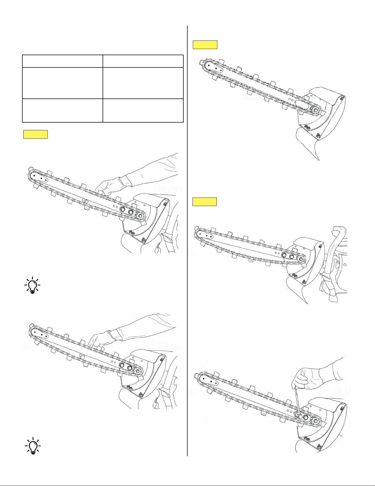
Before you begin, locate the mounting plate [3],
M12 bolts [8], washers [10] and lock washers [9].
Read and understand the chain-tensioning
guide before operation.
3. Attach the mounting plate.
Notice:
Tip
Tip
8
Step 1, Continued:
4. Tension the chain.
Insert a athead screwdriver into the tensioning hole
in the chain bar. Force the bar out, away from the pow-
er head, until you reach the desired chain tension.
You may need to tap the bar back and start again if the
chain becomes too tight.
5. Attach the chain guard.
Use a socket wrench (not included) or impact driver to
rmly tighten the bolts.
Once the desired chain tension is reached, securely fas-
ten the mounting plate [3]. (See the Chain Tensioning
Guide for more details.)
Use a socket wrench (not included) or impact driver to
rmly tighten the bolts.
Review the chain-tensioning guide (next page)
carefully before operation.
Use the M8 bolts [11] and lock washers [12] to attach
the chain guard [4] onto the main mount [1].
e bolt holes are located above the drive sprocket [5].
Notice:
Soil type Chain tension
loose top soil;
hard, compacted soil;
clay
1”
between bottom of digging bar and inside
of digging chain
moderately rocky soil;
sandy, coarse soil
1 ½”
between bottom of digging bar and inside
of digging chain
Notice:
Notice:
Tip
Tip
9
Chain Tensioning Guide
Above: Chain is tensioned to 1” for normal top
soil.
Use the small end of the combination wrench
tool to measure approximate spacing between
bottom of digging bar and inside of digging
chain.
1”
Check chain tension occasionally during
operation!
• Chain tension can slip and may require
adjustment!
The chain tension must be adjusted according to
soil type.
1 ½”
Above: Chain is tensioned to 1 ½” for coarse
soil.
Use the large end of the combination wrench
tool to measure approximate spacing.
Tighten the bolts [8] rmly before use.
• We recommend using a socket wrench (not in-
cluded) or impact driver to make sure bolts are
tight.
too tight!
too loose!
Too much slack in the chain causes excessive
wear to external parts and may damage the
main mount and guards.
Over-tightening the chain may cause binding
and excess wear to the drive belt and/or clutch.
1
2
10
3
4
5
6
7
8
11
12
13
14
15
16
17
9b
9a
10
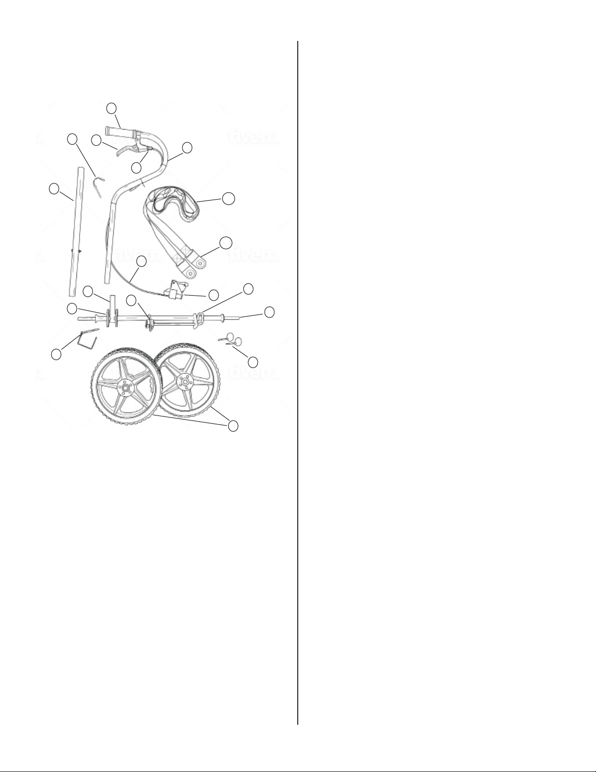
Step 2: Assembling the Cart
Lay out all the parts in an area where you have
plenty of space to assemble the cart. Locate the
axle [10C].
Cart Parts
ref. # description part #
1C grip 26-173
2C (throttle) lever 26-172
3C cable-tension adjuster
4C throttle cable 26-148
5C trigger-extension accessory
6C throttle-extension arm 26-129
7C pivot arm (spring-loaded
end faces axle) 26-133
8C shaft-locking pin
9C-a strap 26-131
9C-b strap plates (x 2)
10C axle
26-135
11C mounting lock
12C mounting guide
13C handle-mount bar
14C pivot plate
15C clevis pin
16C lynch pins (x 2)
17C wheels (x 2) 26-174
}
}
}
}
Tip
Tip
11
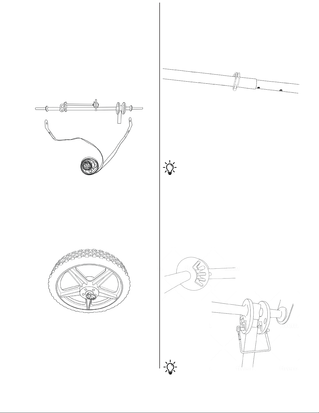
1. Put the metal strap plates over either
end of the axle.
e strap [9C-a] is used to pull the cart along as you
work.
Angle the plates [9C-b] inward when mounting them
on the axle [10C] as shown, and don’t twist the strap.
Put the wheels [17C] on either end of the axle [10c].
Insert the lynch pins [16c] and ip them into the locked
position.
e pivot arm [7C] is unidirectional, with a
spring-loaded end that mounts towards the cart’s axle
[10C]. Check that the spring is facing the opposite
direction before you insert the throttle extension arm.
2. Put the wheels on the axle and insert
the lynch pins.
3. Put the throttle-extension arm and
pivot arm together, and set the
locking pin.
e throttle-extension [6C]/pivot arm [7C] is adjust-
able in length: set the pin [8C] accordingly.
4. Mount the pivot/throttle-extension
arm onto the axle.
When using the mini-trencher, the pivot/throttle-ex-
tension arm [6C + 7C] is used to push the nose of the
trencher down, into the ground, while driving the en-
gine.
Locate the clevis pin [15C] before you begin.
A. Push the pivot arm [7C] in, depressing the
spring, to set the clevis pin [15C].
B. Set clevis pin by passing it thru both sides
of the pivot plate [14C], thru the slot in the
pivot arm [7C], and thru the handle mount
bar [13C], while the spring is depressed.
is may take a couple tries.
Don’t worry which slot in the pivot plate the pin passes
through; more about that in Adjusting the Cart Arm,
below.
Step 2, Continued:
DO NOT attempt to operate without mounting
lock engaged!
locked position
open position
tab
throttle cable
cable-tension
adjuster
trigger lever
velcro strap
12
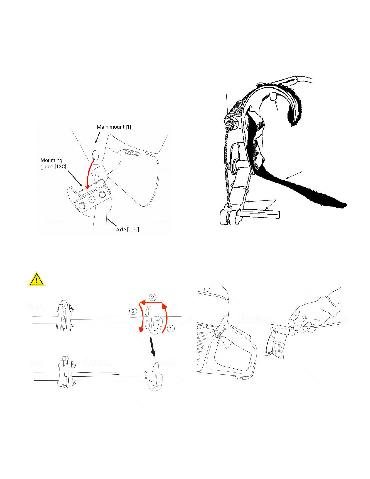
Step 3: Mounting the Mini-trencher
on the Cart
1. Seat the mini-trencher on the cart.
With the chain mounted and the cart assembled,
you’re ready mount the mini-trencher on the cart.
2. Slide the mount lock into place.
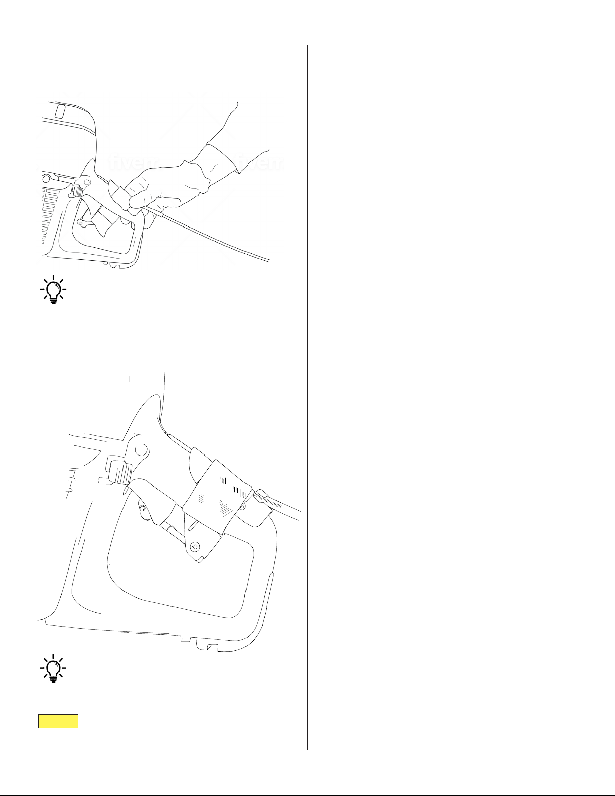
3. Mount the trigger-extension
accessory:
Locate mounting lock [11C] and guide [12C]. Make
sure the lock is open. Li the mini-trencher by the han-
dle, align the ange with the guide, and set the trencher
onto the cart.
A. Orient the throttle accessory so that it’s fac-
ing the right direction, and open the velcro
strap.
Tip
Tip
Notice:
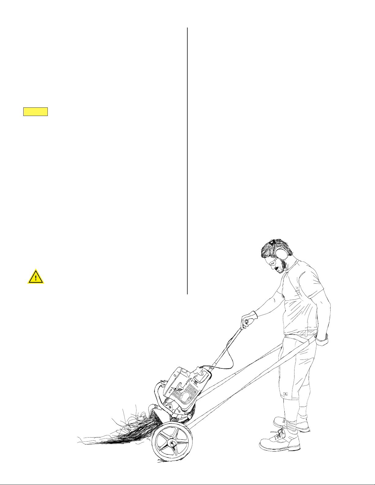
13
C. Fasten the velcro strap securely.
D. Adjust the trigger lever so that it sits snugly
on the throttle trigger.
Step 3, Continued:
B. Set the accessory over handle, as shown,
depressing the safety (a.k.a. throttle-trigger
lockout).
During and after starting the engine, you
may need to readjust the trigger-extension
assembly. If the throttle lever doesn’t work, the
cable may have become loose or disconnected.
Use the cable-tension adjusters as needed.
There’s one tension adjuster on the accessory
and another on the throttle-extension arm.
The tab on the inside surface of the accessory
ts into the space behind the safety lockout.
Notice:
14
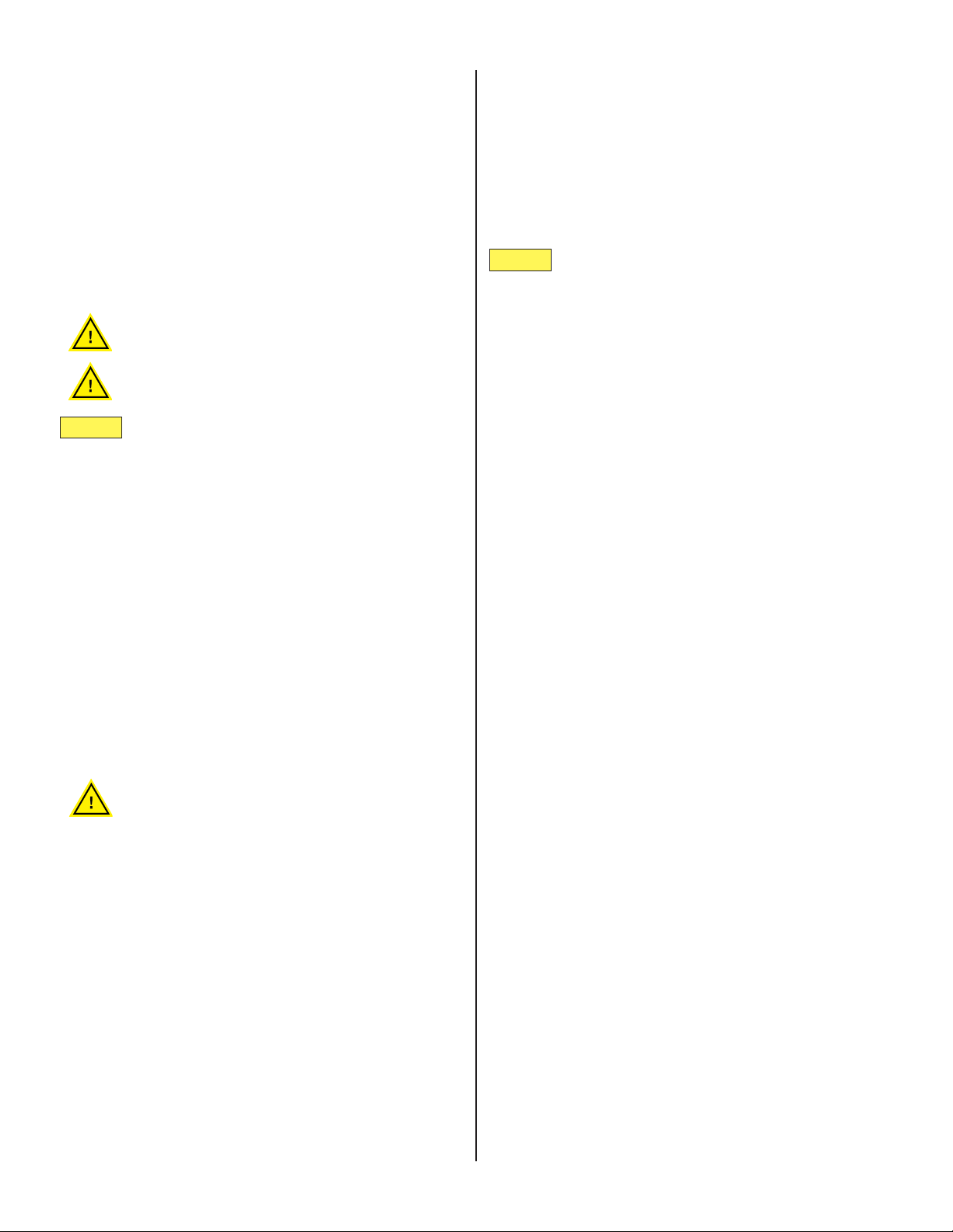
Digging a Trench
In general, the process is the following:
1. Assemble the mini-trencher and mount it
on the cart.
2. Get the mini-trencher into position over
It takes a little practice to get procient with the
mini-trencher. Read on for a few tips and strate-
gies for success.
the area you want to dig, and strap on the
belt.
3. Start the engine (we use the trigger on the
power head to get it started, then adjust the
tension on the throttle cable as needed),
and then move up to the throttle-extension
arm [6C] to power the engine.
4. Get the chain rotating at a moderate speed
(50-75%) before you bring it into contact
with the ground. Too high a speed risks
throwing projectiles and too low can cause
a stall.
5. Work the nose of the mini-trencher into the
ground to desired depth, up to 90 degrees.
e angle of the digging chain determines
the depth of trench.
Before beginning, strap on belt to avoid
entanglement.
6. Adjust the pivot arm as needed. We recom-
mend holding the rear handle of the power
head when adjusting.
7. Use the belt to pull the weight of the tren-
cher towards you, in the direction you want
to dig the trench.
8. Use a rocking motion to get to get past
compacted soil and minor obstacles.
9. If you strike large rocks, thick tree roots,
Never operate on the downhill side of the
machine!
• If operating on a slope, operator should stay
on the uphill-side of the machine.
Adjusting the cart arm
e cart arm (throttle-extension/pivot arm) allows
you to exert downward pressure on the nose of the
mini-trencher and control depth. Adjust it as needed.
1. Hold the rear handle of the power head, de-
press the clevis pin [15C] inward to disen-
gage from the pivot plate [14C], and pivot
the throttle-extension arm up or down.
2. Once adjusted, release inward pressure to
re-engage the pivot plate.
Notice:
Notice:
15
MaintenanceandTroubleshooting
Proper care and maintenance of the power head
improves overall function of TrencherPro parts.
The power head includes a clutch, drive belt, and
belt tensioning system. Review the power head
manual and understand how these systems work
before operating the machine.
See power head manual for detailed information
about servicing and maintaining the drive belt,
carburetor, starter, fuel system, air lter, clutch,
and general troubleshooting.
Never run the engine in a conned or poorly
ventilated space.
Always stop engine and allow parts to cool
down before servicing.
Periodically check chain for damage and lodged
debris.
Aer each use, take a sti brush and clean debris o of
the digging chain. Lightly spray with oil. For long-term
storage, remove chain and place in oil bath.
Maintaining the digging chain
e heavy-duty digging chain and drive belt are parts
designed to wear over time. Check, tension, and re-
place these parts regularly for best results.
• To extend chain life, adjust the chain ten-
sion to t the soil type.
• e working life of a digging chain is great-
ly impacted by soil type.
Parts designed to wear
Never attempt to operate device with a
damaged, heavily rusted, or otherwise faulty
chain.
For detailed instructions on how and when to ten-
sion or replace the drive belt, see power head manual:
Drive belt tension and replacement
Solution: Correctly tension drive belt.
1. Turn o engine. Allow to cool.
2. Remove cover guard. Inspect drive belt and
tensioner visually and check belt tension.
3. See power head manual for instruction on
tensioning drive belt.
Common problems and solutions
Problem: Engine is revving but chain isn’t
rotating
Solution: Adjust tension of digging chain.
1. Turn o engine. Allow engine and chain to
cool.
Problem: Chain is binding, possibly
causing engine to stall
The chain tends to tighten itself with use
and needs periodic adjustment. Rocks stuck
between the digging chain and bar also tighten
chain tension. The mini-trencher performs best
with a certain amount of slack in the chain.
Stop and check the chain tension.
Problem: Pivot arm not engaged
Solution: Make sure that the clevis pin [15C] is en-
gaged in the pivot plate [14C]. See ‘Adjusting the cart
arm’ above.
e pivot arm should be used to adjust the downward
pressure on the nose of the trencher, not to push or
pull the cart forward or backward. Use the strap to pull
the cart in the direction of your trench.
Problem: Throttle lever not working.
Solution: Trigger-extension cable is disengaged.
Check the throttle extension accessory [5C] and throt-
tle lever [2] to make sure the cable is engaged properly
tensioned.
Problem: Rock stuck in digging chain/
bar.
Solution: Remove rock and re-tension digging chain.
1. Turn o engine. Allow engine and chain to
cool.
2. Once cool, rotate chain reverse of operating
direction to dislodge rock.
Problem: Rocks continually stuck in
digging chain/bar.
Solution: Change the nose sprocket.
1. Turn o engine. Allow engine and chain to
cool.
2. 2. See ‘Changing the nose sprocket’ below.

16
Changing the nose sprocket: 6 tooth vs.
11 tooth.
See fuel specications in power head manual for your
specic model.
Use minimum of 87 octane unleaded fuel, with the
correct mixture (1:50 or 2%) of two-stroke oil for
air-cooled engines. Never use two-stroke oil intended
for water-cooled engines. Never use oil intended for
four-stroke engines. Mix the fuel and oil in a clear con-
tainer intended for gasoline. Do not start the engine if
fuel has been spilled nearby as sparks may cause a re.
Transport and store the machine upright so that there
is no risk of fuel leakage. For long-term storage, drain
the fuel mixture from the machine.
Fuel and two-stroke oil:
MaintenanceandTroubleshooting
Continued:
Solution: See Husqvarna manual for detailed informa-
tion about “Starting and Stopping,” (pp 24-26).
Problem: Engine won’t start, or starts
with difculty
Changing the sprocket is fairly straightforward. To
change the nose sprocket:
1. Heat the screws to loosen the locking com-
pound.
2. Remove the M8 screws [16] using an im-
pact driver.
3. Remove the plates and swap out the sprock-
et.
4. Add a locking compound to the screws
before reinstalling.
5. Tighten the screws to 33Nm.
Failure to add locking compound when
reinstalling sprocket could result in injury or
damage to equipment!
e 6-tooth nose sprocket is designed to clear rocks
from the chain, but has less chain engagement. e
sprocket is ideal for moderately rocky soil, sandy and
coarse soil.
e 11-tooth nose sprocket is ideal for loose top soil,
clay, hard and compacted soil.

TRENCHER PRO
Warranty Information
IMPORTANT NOTICE
We, the manufacturer, reserve the right to change the product and/or specications in this manual
without notication. The manual is for information use only and the pictures and drawings depicted
herein are for reference only.
Warranty Repair and Service
Do not return this product to the store for warranty issues or repair. Call our customer service
department at 720-437-7640 for the location of the nearest service center.
Record the information below for future reference.
Model No. ____________________________________________________________________________
Serial No. ____________________________________________________________
Date of Purchase ______________________________________________________________________
Place of Purchase _____________________________________________________________________
For Service or Questions:
Call 720-437-7640

Registration
Acceptance of responsibility:
I (purchaser) have read the User Guide & Manual and Limited Warranty or someone has read and
explained all instructions to me. I understand this warranty does not cover any labor and that all
disputes will be settled by binding arbitration. Warranty void if any attempt to repair or replace defective
parts has been made by unauthorized personnel. The mark next to each item below conrms my
acceptance of responsibility for the use and maintenance of this mini-trencher. I understand that I
alone am responsible for the proper maintenance, care, and safe operation of this mini-trencher.
Received, read, and understand this User Guide & Manual
Understand the safety warnings
Specications accepted
Operations understood
Maintenance requirements understood
I (purchaser) understand that persons who have not read and understood the operator’s manual should
not be allowed to use the machinery. Children should not operate or be near the equipment. Anyone
operating the mini-trencher must have rst read the general safety and use guidelines sections of the
manual.
Is this mini-trencher used by a business?
Yes, business type: _____________________________________________________
No
Owner / Purchaser Signature: ________________________________________________________
The warranty may be refused if the registration is not completed, signed, and legible. It is the
responsibility of the purchaser to assure that the registration form is returned to us, post-marked within
two weeks of date of purchase.
TrencherPro product warranty offers one year warranty against defects in workmanship.
The warranty gives the consumer certain and specic rights which may vary from state to state.
Warranty does not cover normal wear, misuse, neglect, abuse, improper maintenance, overload beyond
rated capacity, accidents, cosmetic defects, consumables, non-authorized replacement parts or
accessories, operation with inadequate supply of gear box oil, improper uid types, or unauthorized
adjustments.

TRENCHER PRO
WARRANTY VOID IF REGISTRATION IS NOT POST MARKED WITHIN 15 DAYS OF PURCHASE.
Mail to:
ToolTuff
15000 West 44th Ave, Suite B
Golden, CO 80403
Serial #: _________________________________________________________Purchase Date: _______________________
Purchased From: ______________________________________________________________________________________
Purchaser: ___________________________________________________________________________________________
Purchaser’s Street Address: ___________________________________________________________________________
City: ___________________________________________________________________________________________________
State: ______________________________________________________ Zip Code: _________________________________
Phone:__________________________________________________________
Email: _________________________________________________________
Attach a copy of receipt or proof of purchase.
To complete registration electronically, ll out and scan the Registration pages and email them to:
customerservice@tooltuffdirect.com
For Service or Questions:
Call 720-437-7640
This manual suits for next models
2
Table of contents


