Triax CCE 210 User manual

TRIAX - your ultimate connection
A
CLASS
KLASSE
Assembly Instructions
Art. No. 325166 GB
CCE 210
Head-End Digital Encoder

- 2 - CCE 210
Contents
1 Safety regulations and notes........................................................................4
2 General information ....................................................................................5
2.1 Packing contents..............................................................................5
2.2 Meaning of the symbols used ............................................................5
2.2 Technical data.................................................................................5
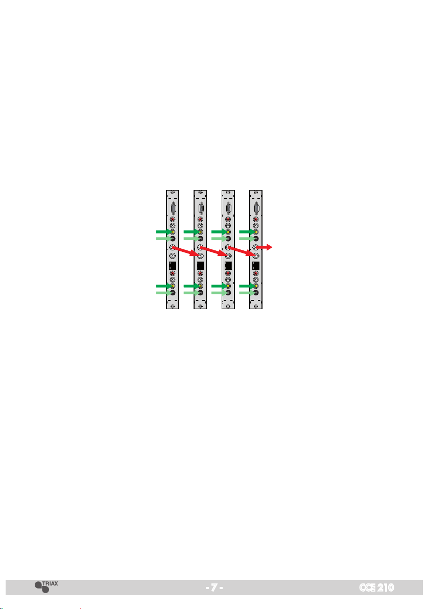
2.3 Description......................................................................................7
Software versions.............................................................................7
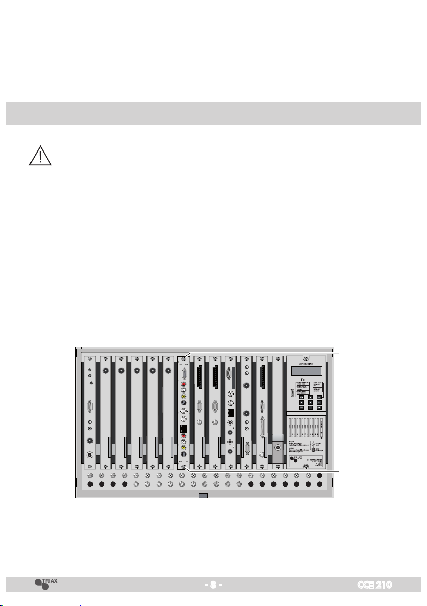
3 Assembly....................................................................................................8
3.1 Installing the cassette........................................................................8
3.2 EMC regulations..............................................................................9
3.3 Cassette overview..........................................................................10
3.4 Connecting the cassette ..................................................................10
4 The control panel at a glance.....................................................................11
4.1 Menu items ...................................................................................11
4.2 Control panel ................................................................................11
5 Programming............................................................................................12
5.1 Programming procedure .................................................................12
5.2 Programming the cassette ...............................................................15
Selecting the cassette .....................................................................15
Ethernet parameters .......................................................................16
IP address of the cassette.............................................................16
Address range (subnet mask) .......................................................17
Address of the gateway...............................................................17
UDP port ...................................................................................18
Output signal path .........................................................................18
Output signal path "ASI" .............................................................18
ASI transfer rate .........................................................................19
ASI options ................................................................................19
Output signal path "IP MPTS"/"IP SPTS" ........................................20
Transmission protocol..................................................................21
Port number ...............................................................................21
Quantity of data packets .............................................................22
Forward error correction..............................................................22
Transmission channel .................................................................22
Output IP address .......................................................................23
Input parameter.............................................................................23
Data rate of the video signal........................................................24

- 3 - CCE 210
Video signal type........................................................................24
TV standard ...............................................................................25
Aspect ratio ...............................................................................25
Sharpness..................................................................................25
Teletext option ............................................................................26
Audio signal type and bit rate......................................................26
Level of the audio signal..............................................................27
Programme number (SID - Service ID)............................................27
Channel name............................................................................27
ASI station filter .............................................................................28
Transport stream ID and ORGNET ID ...............................................30
NIT ..............................................................................................30
Factory reset .................................................................................31
Saving settings .............................................................................31
6 Final procedures........................................................................................32
6.1 Combination with other cassettes.....................................................32

- 4 - CCE 210
1 Safety regulations and notes
• Assembly, installationandservicingshouldbecarriedoutbyauthorised
electricians.
• Switchofftheoperatingvoltageofthesystembeforebeginningwithassem-
bly or service work or pull out the mains plug.
• Donotperforminstallationandserviceworkduringthunderstorms.
• Installthesystemsoitwillnotbeabletovibrate…
- inadust-free,dryenvironment
- insuchamannerthatitisprotectedfrommoisture,fumes,splashingwa-
ter and dampness
- somewhere protected from direct sunlight
- not within the immediate vicinity of heat sources
- in an ambient temperature of 0 °C to +50 °C. In case of the formation of
condensation wait until the system is completely dried.
• Ensurethatthehead-endstationisadequatelyventilated.Donotcoverthe
ventilation slots.
• Bewareofshortcircuits
• Noliabilityisacceptedforanydamagecausedbyfaultyconnectionsor
inappropriate handling.
• Observetherelevantstandards,regulationsandguidelinesontheinstalla-
tion and operation of antenna systems.
• ThestandardsIEC/EN/DINEN50083resp.IEC/EN/DINEN60728must
be observed.
• For further information please read the assembly instructions for the head-
end station used.
• Test the software versions of the head-end station and the cassette and
update them if necessary. The current software versions can be found at
"www.triax.com".
Take action to prevent static discharge when working on the device!
Electronic devices should never be disposed of in the household rubbish. In
accordance with directive 2002/96/EC of the European Parliament and the
European Council from January 27, 2003 which addresses old electronic and
electrical devices, such devices must be disposed of at a designated collection
facility. At the end of its service life, please take your device to one of these
public collection facilities for proper disposal.

- 5 - CCE 210
2 General information
2.1 Packing contents
1 Cassette CCE 210
1BNCcable 1LANcable(RJ45)
1Briefassemblyinstructions 1 CD (assembly instructions)
2.2 Meaning of the symbols used
Important note
—> General note
• Performingworks
2.2 Technical data
The devices meet the following EU directives:
73/23/EWG,89/336/EWG
The product fulfils the guidelines and standards for CE labelling.
Unless otherwise noted all values are specified as "typical".
CVBS Video Input:
Standard: ..................................................................... DIN EN 50049-1
Input level: .....................................................................................1 Vpp
Input impedance:............................................................................ 75 Ω
Frequencyrange:........................................................... 20Hz…5MHz
S-Video (Y/C) Input:
Standard: ..................................................................... DIN EN 50049-1
Input level:
Y (Luminance).................................................................................1 Vpp
C (Chrominance) ............................................................................1 Vpp
Input impedance:............................................................................ 75 Ω
Frequencyrange:........................................................... 20Hz…5MHz
Audio Input:
Standard: ..................................................................... DIN EN 50049-1
Input level: ..............................................................................500 mVrms
Input impedance:...........................................................................10 kΩ
Frequencyrange:........................................................... 20Hz…15kHz

- 6 - CCE 210
Encoder:
Transport stream: ..............................................MPEG2 (ISO/IEC 13818-1)
Output data rate:.......................................................2Mbit/s…15Mbit/s
Video data stream: .......................................... MPEG2 (ISO/IEC 13818-2)
Audio data stream: ........................................... MPEG1 (ISO/IEC 11172-3)
Audio data rate:........................................................192kb/s…384kb/s
ASI Interfaces
Standard: .....................................................................DIN EN 50083-9
Format:................................................................MPEG ISO IEC 13818-1
max. data rate .......................................................................108 Mbit/s
User data rate: ................................................................. 2…90Mbit/s
Impedance:.................................................................................... 75 Ω
Level (input / output): ..................................................... 800 mVpp ± 10%
Rise/Fall Time:..............................................................< 1.2 ns (20-80%)
Reflexion loss (input):........................................... >17dB(5…270MHz)
LAN Interface
Standard: .................................................................10/100/1000MB/s
Transport streams:....................SPTS (Single Programme Transport Stream),
MPTS (Multi Programme Transport Stream)
Protocols:.......................................................... UDP(UserDataProtocol),
RTP (Real-Time Transport Protocol)
Connections:
Audio inputs: ...................................................................4 Cinch sockets
Video inputs: ..................................................................2Cinchsockets,
2 S-Video sockets (Mini-DIN)
LAN:................................................................................1RJ45socket
ASI input: .................................................................1BNCsocket,75Ω
ASI output:................................................................1BNCsocket,75Ω
Connection strip (10-pin):.........................................
for supply voltages and
control circuit
RS-232 socket: .......................................................serial update interface
Remote maintenance
Remotely controllable (via
CCRS 1000
*):................................................yes
Remoteupdate(viaBEflash*):..............................................................yes
(* and a corresponding management unit)

- 7 - CCE 210
2.3 Description
In the cassette CCE 210 two analogue audio and video signals are converted
into MPEG2 data streams (transport streams).
The transport streams are emitted via the LAN interface or the ASI output.
Thecassetteisequippedwithtwostereo/audioinputs,two(S-)videoinputs
and one ASI data stream input. The fed in analogues signals are digitized and
supplied to an encoder that encodes them in real time.
The stereo audio signals are transferred via an adjustable amplifier to the
encoder. The bit rates are adjustable. A transport stream fed via the ASI input
socket will be inserted into the transport streams of the encoded analogous
signals. In this way it is possible to connect several
CCE 210
in series.
AttheASIoutputsockets(BNC)atransportstreamisprovidedaccordingto
ISO/IEC 13818-1. Alternatively one IP MPTS data stream or two IP SPTS data
streams(equippedwithIPaddresses)canbeprovidedatthenetworksocket.
The cassette is designed for use in head-end systems CSE 3300.
Software versions
Cassette
After activating the cassette the software version of the cassette is displayed
(see page 15).
Control unit
To operate these cassettes the software version of the control unit must be
"V43" or higher. Approx. 5 minutes after the last keypress the software version
of the control unit is displayed.

- 8 - CCE 210
Ifnecessary,youcanactivatetheindicationofthesoftwareversionofthe
control unit manually:
• Pressanytwokeysonthecontrolunitofthehead-endstationsimultaneously
untilthedisplaygoesdarkandthesoftwareversion,e.g.
"
V 43
"
appears
.
3 Assembly
3.1 Installing the cassette
– Ensure the head-end station is mounted so it will not be able to vibrate.
Avoid,forexample,mountingthehead-endstationontoaliftshaftorany
other wall or floor construction that vibrates in a similar way.
– Beforeinstallingorchangingacassetteunplugthepowercablefromthe
mains power socket.
• Removethefasteningscrews1of an unoccupied slot from the bracket of
the head-end station.
• Insertthecassetteinthisslotandpushitintothehousing.
• Alignthecassetteandapplyslightpressuretoconnectittotheconnections
of the board and the HF bus bar.
• Fastenthecassettewiththescrews1.
0°
1
1

- 9 - CCE 210
3.2 EMC regulations
To comply with the current EMC regulations, it is necessary to connect the lines
leading in and out of the head-end station using cable terminals.
When mounting the cassette in a head-end station which is installed in a 19"
cabinet, make sure the connections leading in and out for the 19" cabinet are
made using cable terminals.
CLASS
KLASSE
The attenuation of shielding of the connection lines for ASI and antenna must
meet the requirements for "Class A".
• Inserttherequirednumberofcableterminalsintheopeningsprovidedin
the head-end station or in the 19
"
cabinet.
Tighten the nuts on the cable terminals until the teeth on the lock washer have
penetrated the exterior coating and a good connection is made between the hous-
ing and cable terminals.

- 10 - CCE 210
3.3 Cassette overview
12
13
11
10
9
8
7
6
5
4
3
2
1
1 D-SUBsocket"RS232"
2Audio input R AV1 (Cinch)
3Audio input L AV1 (Cinch)
4Video input AV1 (Cinch)
5S-Video input AV1 (Mini-DIN)
6 ASIoutput(BNC)
7 ASIinput(BNC)
8 Ethernetsocket(RJ45)
9Audio input R AV2 (Cinch)
0Audio input L AV2 (Cinch)
!Video input AV2 (Cinch)
@S-Video input AV2 (Mini-DIN)
#MAC Address (at the frame)
The operating software of the cassette can be updated via
the9-pinD-SUBsocket"RS232"usingaPCornotebookand
the software "BE-Flash". You can find the current operating
software on the website "www.
triax.com
".
3.4 Connecting the cassette
• Connect the
peripheral devices via cable terminals to the input sockets
"Video" 4/!or "S-Video" 5/@, "Audio R" 2/9and "Audio L"
3/0of the channel strips "A" and "B".
—> Connect a mono audio signal to input "Audio L"
3/0
.
• Connectthe
ASI input
7
and the
ASI output 6
to the peripheral devices
-
or
• connecttheLANsocket8.
• Connectthehead-endstationtothemains.

- 11 - CCE 210
4 The control panel at a glance
4.1 Menu items
Program the cassette using the buttons on the control unit of the head-end sta-
tion. The two-line display of the control unit then shows the menus.
Use the key to select the following main menu items:
– Cassette
– Ethernet
– Output
– Input
– ASI
– TS/ONID
– Factory reset
4.2 Control panel
The key pad on the head-end station is used to scroll through the menus:
scrolls forward through the menus.
scrolls backward through the menus.
select parameters in the menus
selects sub-menus
setvalues,.
saves all entries.
BE-Remote V43
please wait . . .

- 12 - CCE 210
5 Programming
5.1 Programming procedure
Bedienhinweise
"blättert" Menüs vorwärts.
"blättert" Menüs rückwärts.
wählen die Eingabeposition
wählt Untermenü
stellen Werte ein,.
speichert alle Eingaben.
1zeigt die Eingabeposition
Operating Hints
scrolls forward through the menu.
scrolls backward through the menu.
select the enter position.
selects a submenu.
set values and triggers actions.
saves all entries.
1shows the enter position
BE–Remote V 43
Bx 2
V 3
ENCODER
– – –
Bx 2
0x0001,0100
TS/ONID
Bx 1
………
………
………
Bx 3
………
> 2 sec. = abbrechen / cancel
………
………
t > 10 s
Bx 2
off =>
ETHERNET
Options
stat
DHCP
Bx 2
192.168.
IP-ADDR
0.128
Bx 2
255.255.
IP-MASK
255. 0
Bx 2
192.168.
IP-GATEWAY
0. 1
Bx 2
60000
UDP-PORT
A
B
Ein/On
Bx 2
ASI
ASI
OUTPUT
=>
IP MPTS
IP SPTS
IP MPTS
IP SPTS
nur/only
IP SPTS
Bx 2
108000 KBits
ASI RATE
Bx 2
188 pos. /204
/neg.
/burst
ASI OPTION
cont.
IP 1
UDP /RTP
1…7
/ 10/09 AnnexB /
… / 20/19 AnnexB
1…7
/ 10/09 AnnexB /
… / 20/19 AnnexB
/RTP
MODE/PORT
1234
Bx 2
AV 1
INPUT
=>
Bx 2
Filter
ASI
off
on
/AV 2
AV 1/2
5 Mbps
BITRATE
AV 1/2
Composite
INPUT
AV 1/2
PAL BG
NORM
4.43 MHz
AV 1/2
4:3
ASPECT
AV 1/2
normal
SHARPNESS
AV 1/2
Stereo
AUDIO
256 kbps
AV 1/2 VOLUME
0 dB
AV 1/2
1
PRG-NUM
(0x0020. . . )
AV 1/2
PROG 1
NAME
/S-Video
/Audio only/2…15/off
/PAL N
/16:9
/sharp/soft
AV 1/2
ON
TELETEXT
/OFF
/Joint/Dual/Mono L
/256/320/384
1…255 !
-11…+11
! = Programmnummer
ist bereits belegt
! = Programme number
is already in use
IP 1
7 off
PKTS/FEC
IP 1
227. 40.
OUT-IP
50. 60
IP 2
UDP
RTP
MODE/PORT
1234
IP 2
7 off
PKTS/FEC
IP 2
227. 40.
OUT-IP
50. 61
Services entfernen / hinzufügen
Removing / activating services
nächster Service (Programm)
next service (station)
on / off
on / off
01/07ASI TV +
Das Erste
Bx 2
off
NIT
M
B
A
▶
Bx 2
Defaults
FACTORY
=>
Bx 2
STORE
FACTORY
=> M
auf Werkseinstellung
zurücksetzen und speichern
reset to factory defaults
and store
REMOTE

- 13 - CCE 210
Bedienhinweise
"blättert" Menüs vorwärts.
"blättert" Menüs rückwärts.
wählen die Eingabeposition
wählt Untermenü
stellen Werte ein,.
speichert alle Eingaben.
1zeigt die Eingabeposition
Operating Hints
scrolls forward through the menu.
scrolls backward through the menu.
select the enter position.
selects a submenu.
set values and triggers actions.
saves all entries.
1shows the enter position
BE–Remote V 43
Bx 2
V 3
ENCODER
– – –
Bx 2
0x0001,0100
TS/ONID
Bx 1
………
………
………
Bx 3
………
> 2 sec. = abbrechen / cancel
………
………
t > 10 s
Bx 2
off =>
ETHERNET
Options
stat
DHCP
Bx 2
192.168.
IP-ADDR
0.128
Bx 2
255.255.
IP-MASK
255. 0
Bx 2
192.168.
IP-GATEWAY
0. 1
Bx 2
60000
UDP-PORT
A
B
Ein/On
Bx 2
ASI
ASI
OUTPUT
=>
IP MPTS
IP SPTS
IP MPTS
IP SPTS
nur/only
IP SPTS
Bx 2
108000 KBits
ASI RATE
Bx 2
188 pos. /204
/neg.
/burst
ASI OPTION
cont.
IP 1
UDP /RTP
1…7
/ 10/09 AnnexB /
… / 20/19 AnnexB
1…7
/ 10/09 AnnexB /
… / 20/19 AnnexB
/RTP
MODE/PORT
1234
Bx 2
AV 1
INPUT
=>
Bx 2
Filter
ASI
off
on
/AV 2
AV 1/2
5 Mbps
BITRATE
AV 1/2
Composite
INPUT
AV 1/2
PAL BG
NORM
4.43 MHz
AV 1/2
4:3
ASPECT
AV 1/2
normal
SHARPNESS
AV 1/2
Stereo
AUDIO
256 kbps
AV 1/2 VOLUME
0 dB
AV 1/2
1
PRG-NUM
(0x0020. . . )
AV 1/2
PROG 1
NAME
/S-Video
/Audio only/2…15/off
/PAL N
/16:9
/sharp/soft
AV 1/2
ON
TELETEXT
/OFF
/Joint/Dual/Mono L
/256/320/384
1…255 !
-11…+11
! = Programmnummer
ist bereits belegt
! = Programme number
is already in use
IP 1
7 off
PKTS/FEC
IP 1
227. 40.
OUT-IP
50. 60
IP 2
UDP
RTP
MODE/PORT
1234
IP 2
7 off
PKTS/FEC
IP 2
227. 40.
OUT-IP
50. 61
Services entfernen / hinzufügen
Removing / activating services
nächster Service (Programm)
next service (station)
on / off
on / off
01/07ASI TV +
Das Erste
Bx 2
off
NIT
M
B
A
▶
Bx 2
Defaults
FACTORY
=>
Bx 2
STORE
FACTORY
=> M
auf Werkseinstellung
zurücksetzen und speichern
reset to factory defaults
and store

- 14 - CCE 210
Bedienhinweise
"blättert" Menüs vorwärts.
"blättert" Menüs rückwärts.
wählen die Eingabeposition
wählt Untermenü
stellen Werte ein,.
speichert alle Eingaben.
1zeigt die Eingabeposition
Operating Hints
scrolls forward through the menu.
scrolls backward through the menu.
select the enter position.
selects a submenu.
set values and triggers actions.
saves all entries.
1shows the enter position
BE–Remote V 43
Bx 2
V 3
ENCODER
– – –
Bx 2
0x0001,0100
TS/ONID
Bx 1
………
………
………
Bx 3
………
> 2 sec. = abbrechen / cancel
………
………
t > 10 s
Bx 2
off =>
ETHERNET
Options
stat
DHCP
Bx 2
192.168.
IP-ADDR
0.128
Bx 2
255.255.
IP-MASK
255. 0
Bx 2
192.168.
IP-GATEWAY
0. 1
Bx 2
60000
UDP-PORT
A
B
Ein/On
Bx 2
ASI
ASI
OUTPUT
=>
IP MPTS
IP SPTS
IP MPTS
IP SPTS
nur/only
IP SPTS
Bx 2
108000 KBits
ASI RATE
Bx 2
188 pos. /204
/neg.
/burst
ASI OPTION
cont.
IP 1
UDP /RTP
1…7
/ 10/09 AnnexB /
… / 20/19 AnnexB
1…7
/ 10/09 AnnexB /
… / 20/19 AnnexB
/RTP
MODE/PORT
1234
Bx 2
AV 1
INPUT
=>
Bx 2
Filter
ASI
off
on
/AV 2
AV 1/2
5 Mbps
BITRATE
AV 1/2
Composite
INPUT
AV 1/2
PAL BG
NORM
4.43 MHz
AV 1/2
4:3
ASPECT
AV 1/2
normal
SHARPNESS
AV 1/2
Stereo
AUDIO
256 kbps
AV 1/2 VOLUME
0 dB
AV 1/2
1
PRG-NUM
(0x0020. . . )
AV 1/2
PROG 1
NAME
/S-Video
/Audio only/2…15/off
/PAL N
/16:9
/sharp/soft
AV 1/2
ON
TELETEXT
/OFF
/Joint/Dual/Mono L
/256/320/384
1…255 !
-11…+11
! = Programmnummer
ist bereits belegt
! = Programme number
is already in use
IP 1
7 off
PKTS/FEC
IP 1
227. 40.
OUT-IP
50. 60
IP 2
UDP
RTP
MODE/PORT
1234
IP 2
7 off
PKTS/FEC
IP 2
227. 40.
OUT-IP
50. 61
Services entfernen / hinzufügen
Removing / activating services
nächster Service (Programm)
next service (station)
on / off
on / off
01/07ASI TV +
Das Erste
Bx 2
off
NIT
M
B
A
▶
Bx 2
Defaults
FACTORY
=>
Bx 2
STORE
FACTORY
=> M
auf Werkseinstellung
zurücksetzen und speichern
reset to factory defaults
and store

- 15 - CCE 210
5.2 Programming the cassette
—> Pressing the button for longer than 2 seconds cancels the
programming procedure. This takes you back to the programme
item "Selecting the cassette" from any menu. Any entries that have
not been saved are reset to the previous settings.
—> Entries in the menus can be saved by pressing the key. You are
taken back to the "Selecting the cassette" menu item.
—> The parameters and functions to be set are underlined (Cursor).
• Switchonthehead-endstation.
—> The display shows the software version (e.g. V 43)
—> The processor reads the
cassettes
‘ data (approximately 10 sec-
onds).
BE–Remote V 43
t > 10 s
Ein/On
Selecting the cassette
• Ifnecessaryselectthecassettetobeprogrammedbyrepeatedlypressing
the button (e.g. Box 2).
—>
The display shows e.g. the menu "Bx 2 ENCODER":
"Bx 2" stands for slot 2
"
ENCODER
" type of cassette
"V 2" software version of the cassette
Bx 2
V 2
ENCODER
– – –
Bx 1
………
………
………
Bx 3
………
………
………
• Pressthe button.

- 16 - CCE 210
—> The "Ethernet parameters" – "ETHERNET" main menu is activated
.
—> IfyoudonotwanttodoEthernetsettings,pressthe but-
ton.
The "Output signal path" – "OUTPUT" main
menu is activated
(page 18).
Ethernet parameters
In this menu you specify whether the Ethernet parameters for the prospectively
intendedcontrolofthecassetteareentered…
– automatically by a connected server ("DHCP"),
– manually via the menu ("stat")
– or whether you will not use the Ethernet output ("off").
Toassignthecassetteuniquely,eachIPTVcassettemustbeallocateditsown
IP address.
Bx 2
stat
ETHERNET
=>
Bx 2
DHCP
ETHERNET
=>
Bx 2
off
ETHERNET
=>
• Pressthe buttonstoselect…
– manual setting ("stat")oftheEthernetparameter,
– automatic setting ("DHCP") of the Ethernet parameter or
– to deaktivate Ethernet ("off").
• Pressthe
button to activate the setting options ("Options").
—> The "IP address of the cassette" – "IP-ADDR" submenu is activated.
IP address of the cassette
IfyouchoosetoentertheEthernetparametersmanually,settheIPaddressof
the cassette in this menu. If "DHCP"isselected,the"IP-ADDR","IP-MASK" and
"IP-GATEWAY" sub-menus display the parameters that were assigned automati-
callybyaconnectedserver.Ifaserverisnotconnected," 0. 0. 0. 0*"
appears in the corresponding menu. The star " *" in the display means that
the data is provided by a DHCP server.
Bx 2
192.168.
IP-ADDR
0.128

- 17 - CCE 210
• Usethe
buttons
to select the digits of the IP address displayed to be
set and use to set the IP address wished.
• Pressthe button.
—> The "Address range (subnet mask)" – "IP-MASK" submenu is activated.
Address range (subnet mask)
In this menu you define the address range for the cassettes connected to the
LAN network.
Bx 2
255.255.
IP-MASK
255. 0
• Usethe
buttons to select the digit of the subnet mask displayed to be set
and use
to set the subnet mask wished.
• Pressthe button.
—> The "Address of the gateway" – "IP-GATEWAY" submenu is activated
Address of the gateway
The address of a gateway (server) can be set in this menu. If no gateway is
used you can skip this setting.
Bx 2
192.168.
IP-GATEWAY
0. 1
• Usethe
buttons to select the digit of the IP address displayed to be
set and use to set the IP address wished.
• Pressthe button.
—> The "UDP port" – "UDP-PORT" submenu is activated
.

- 18 - CCE 210
UDP port
TheUDPportsettingisrequiredifthecassetteneedstobereachedexternally
for remote maintenance.
Bx 2
60000
UDP-PORT
• Usethe
buttons to select the digit of the port number displayed to be set
and use
to set the port number wished ("0"…"65535").
• Pressthe button.
—> Return to the main menu "Ethernet parameters"
• Pressthe button.
—> The "Output signal path" – "OUTPUT" main menu is activated.
—> Ifyoudonotwanttodooutputsettings,pressthe button.
The "
Input parameter
" – "INPUT" main
menu is activated
(page 23).
Output signal path
In this menu you define the signal path of the output transport streams.
Bx 2
ASI
OUTPUT
=>
Bx 2
IP SPTS
OUTPUT
=>
Bx 2
IP MPTS
OUTPUT
=>
• Usethe buttons to set the signal path wished.
—> Output signal path "IP MPTS"/"IP SPTS" see page 20.
Output signal path "ASI"
In this setting the output transport stream is provided via the ASI output. For this
please also note chapter 6.1 "Combination with other cassettes" (page 32).
Bx 2
ASI
OUTPUT
=>

- 19 - CCE 210
• Pressthe
button.
—> The "ASI transfer rate" – "ASI RATE" submenu is activated.
ASI transfer rate
In this menu you set the transfer rate for the ASI component connected (incl.
stuffing - filled up user data rate).
Forthissettingpleasetaketherequiredinformationfromthedocumentation
(technical data) of the ASI component to be connected.
Bx 2
108000 KBits
ASI RATE
• Usethe
buttons
to select the digits to be set for the transfer rate then
use the buttons to set the transfer rate wished.
• Pressthe button.
—> The "ASI options"
– "ASI OPTION" submenu is activated.
ASI options
Inthismenuyoudefinethesizeofthedatapackets,theirpolarityandthetype
of transmission.
Forthissettingpleasetaketherequiredinformationfromthedocumentation
(technical data) of the ASI component to be connected.
Bx 2
188 pos.
ASI OPTION
cont.
• Pressthe buttons to set the size of the data packets ("188" or "204"
bits).
• Ifthepolarityofthedatatobetransmittedhastobechanged,pressthe
to select
"pos." (positive – standard) and using the buttons set
to "neg." (negative).
• Tochangethetypeoftransmissionpressthe
buttons to select
"cont."

- 20 - CCE 210
(continuous – standard) and using the buttons set to "burst".
—> Setting "cont."
The data packets of the user data are collected to a great data
packet in the transport stream.
—> Setting "burst"
The data packets of the user data are spaced out evenly in the trans-
port stream.
• Pressthe button.
—> Return to the main menu "Output signal path"
Output signal path "IP MPTS"/"IP SPTS"
In this setting the output transport stream is provided via the Ethernet socket.
If "
IP MPTS" (Internet Protocol Multi Programme Transport Stream)isselected,
allservices(programmes)fedinviatheAV1,AV2andASIinputsareprovided
in one multi programme transport stream with one IP address.
If "
IP SPTS" (Internet Protocol Single Programme Transport Stream)isselected,
the signal from input
- AV1 is provided in one single programme transport stream with one output
IP address (IP 1).
- AV2 is provided in one single programme transport stream with one output
IP address (IP 2).
• Pressthe buttons to select the signal path wished.
Bx 2
IP SPTS
OUTPUT
=>
Bx 2
IP MPTS
OUTPUT
=>
• Pressthe button.
—>
The"Transmissionprotocol, Port number"– "MODE / PORT" sub-
menu is activated.
Table of contents
Other Triax Media Converter manuals
Popular Media Converter manuals by other brands

Siemens
Siemens SIRIUS 3RS17 Series operating instructions

Power Fist
Power Fist 8876054 manual

Wyrestorm
Wyrestorm RXV-35-4K v1 quick start guide

red lion
red lion N-Tron 1000 Series Hardware guide

Blackmagicdesign
Blackmagicdesign Teranex Mini Series Installation and operation manual

Black Box
Black Box LMC11032A user manual