Triax TVC 06 Quad User manual

User Manual
TVC 06 Opto Re-converter Quad Art. No. 307641
TVQ 06 Opto Re-converter Quatro Art. No. 307640
User
Manua
Bedienungs-
an eitung
Mode
d’emp oi
triax.com

Safety instructions
Warning! Fai ure to comp y with the specified precautionary measures may cause serious injury to persons or damage to property.
The insta ation and commissioning may on y be performed by suitab y qua ified persons, technicians or insta ers in
comp iance with safety regu ations. Damage due to improper insta ation and commissioning, defective connectors
on cab es or any other incorrect hand ing wi void the warranty.
CAUTION: The safety requirements are according to EN 60728-11 and must be observed.
•
Disconnect mains power before working on e ectrica systems.
•
Any additiona e ectrica wiring requirements shou d a ways be insta ed by a suitab y qua ified person(s).
•
Insta ation or service work shou d NEVER be undertaken during e ectrica / thunderstorms.
Introduction
The purpose of this guide is to enab e the successfu insta ation of the Triax TVC 06 QUAD and TVQ 06 QUATRO products.
This guide assumes that;
•
The converter is connected to a suitab e Triax Passive Optica Network (PON),
providing a minimum optica signa eve s of -12/-15 dBm at the connection point of the converter.
•
The converter has been insta ed in a dry environment and mounted with suitab e fixings.
•
The insta ation is carried out by a competent person.
•
A ferru e end faces of the FC/PC optica connectors are c eaned prior to making
a connection using a suitab e fibre optic c eaning kit.
Cables and Connections
Cab es used shou d be industry approved coaxia cab e and shou d be terminated using an F type connector. Fibre optic
cab e shou d be Triax approved sing e mode with FC/PC connections.
Mounting
The device can be fixed on the wa or on a meta p at in a distributor box by using two 4 mm screws direct y.
LED ”Orange”
indicates when RF
power is present
LED ”Green”
indicates that unit is
DC power supp ied
Next connect the FC/PC fibre connector into the optica input of the converter
(ensuring the end is c eaned first) as per the fo owing diagram.
A ign the key-way on the FC-PC
connector, with the key-way on the fibre
receptac e. Push the connector firmly
into the socket.
1
Connector key-way
Receptac e key-way
Ensure the key-way are firm y ocated
be- fore rotating the coup ing ring c ock-
wise onto the receptac e - se Fig. 3
Push firm y to ocate key-ways
Coup ing ring
NOTE: Fai ure to fo ow these instruction
correct y wi resu t in attenuation
3
Rotate c ock-wise to finish
2/8
Attention: Never ook with the eyes into a fibre ine or fibre connector when an optica transmitter is connected!
The aser ight is not visib e but cou d damage the eye.
QUAD and QUATRO Optical Reconverter - Installation Guide
115 mm
115 mm
105
mm
42,5
mm

Use a conventiona signa eve meter or spectrum ana yser to check the output signa s for both sate ite and terrestria on
each output, both types (QUAD or QUATRO) converters can be powered from the meter.
Connect up the required coaxia cab es to each of the outputs. On the QUAD version if terrestria as we as sate ite is re-
quired connection shou d be made via a standard trip ex/quadp ex wa out et. For the QUATRO version the outputs
shou d be connected direct y onto a mu tiswitch.
TVC 06 is DC supp ied from the STB as we as TVQ 06 from mu tiswitch unit. Thus a PSU is not necessary. If on y terrestri-
a is used then connect the externa power supp y onto the converterP ease order PSU TPS 323 (307657) separate y
Important:
Both connections of a STB with Twin-Tuner must be connected to either ports 1&2 or ports 3&4 of the
TVC 06 QUAD but not across any other combination of the ports.
Once a set top boxes are connected and powered up, check for correct operation.
On start up p ease a ow the unit 10 seconds to ca ibrate its own.
Type
Art. No.
TVC 06
307641
TVQ 06
307640
Design
Quad + terrestria
Quatro +
terrestria
for the use with mu ti
-
switches
Optica Input
Input Power with TOL 32 / TOL 64 or TOU 232
dBm
-
12 /
-
13,5
...0
Wave ength
nm
1310/1550
Input RF frequency range, vertica
GHz
0.95
–
3.0
Input RF
frequency range, horizonta
GHz
3.4
–
5.45
Terrestria frequency range, DVB
-
T
MHz
470...854
Terrestria frequency range, DAB
MHz
174...241
Terrestria frequency range, DTT
MHz
88...108
Input connnector
FC/PC
Outputs SAT
Horizonta High Band (input: 4.4 to 5.45 GHz)
MHz
1100
-
2150, > 15,5 V 22 kHz
fix
Vertica High Band (input: 1.95 to 3.0 GHz)
MHz
1100
-
2150, < 14,5 V 22
kHz
fix
Horizonta Low Band (inpiut: 3.4 to 4.4 GHz)
MHz
950
-
1950, > 15,5 V
fix
Vertica Low Band (input: 0.95 to 1.95 GHz)
MHz
950
-
1950, < 14,5 V
fix
Impedance, nomina
Ohm
75
75
Return oss (min.)
dB
10
10
Automatic Gain Contro (AGC)
dB
30
30
Output Leve SAT
switchab e
dBµV
ca. 75
ca. 79
/74
/69
Outputs Terrestria
Terrestria frequency range, DVB
-
T
MHz
470...854
470...854
Terrestria frequency range, DAB
MHz
174...240
174...240
Terrestria frequency range, DTT
MHz
87...108
87...108
Output Leve
DTT
dBµV
ca. 65
ca. 75
Common Data
Output connectors
4 x Ff (4 x SAT/TER)
5 x Ff (4xSAT+1xTER)
Current consumption
mA
125 @ 20V; 225 @ 10V
<400 @ 20V
Input Vo tage
V
10...20
10...20
from receiver
from mu tiswitch
Operating temperature
°C
-
15...+60
-
15...+60
Weight
kg
0,8
0,8
Dimensions
mm
128 x 94 x 27
97 x 61 x 26
Accessories
Power supp y TPS 323 PSU (optiona ) TPS 323 PSU (100-240 VAC +20VDC/1.2A), Best.-Nr. 307657
3/8

Sicherheitshinweise
Warnung! Die Nichtbeachtung der gegebenen Vorsichtsmaβnahmen kann zu Personen– oder Sachbeschädigungen führen.
Die Montage und Inbetriebnahme darf nur von eingewiesenen Personen, Technikern oder Insta ateuren unter Beachtung der
Sich- erheitsbestimmungen durchgeführt werden. Schäden durch fa sche Montage und Inbetriebnahme, feh erhafte
Steckverbindungen an Kabe n oder sonstige unsachgemäβe Handhabung führen zum Er öschen des Garantieanspruchs.
VORSICHT:
Die Sicherheitsanforderungen nach EN 60728-11 sind unbedingt zu beachten.
•
Scha ten Sie vor Arbeiten an e ektrischen An agen immer den Stromkreis ab.
•
Lassen Sie einen evt . notwendigen e ektrischen Ansch uss grundsätz ich vom Fachmann anbringen.
•
Führen Sie Insta ationen oder Servicearbeiten nie bei Gewitter durch.
Einleitung
Diese An eitung dient der erfo greichen Insta ation der TRIAX-Produkte TVC 06 QUAD und TVQ 06 QUATRO
Diese An eitung setzt fo gendes voraus:
•
Der Rückumsetzer ist mit einem passenden passiven optischen Netzwerk (PON) von TRIAX
verbunden. Die Stärke des optischen Pege s iegt bei mindestens -12/-15 dBm am Ansch usspunkt
des Konverters.
•
Der Rückumsetzer wird an einem trockenen Ort und mit passenden Befestigungen angebracht.
•
Die Insta ation wird durch eine qua ifizierte Person durchgeführt.
•
A e Meta kappen und Oberf ächen der optischen FC/PC-Verbinder werden unter Zuhi fenahme eines
geeigneten G asfaser-Reinigungssets vor dem Gebrauch gereinigt.
Kabel und Verbindungen
Die verwendeten Koaxia kabe so ten für den industrie en Einsatz zuge assen und mit F-Steckern konfektioniert
sein. Bei den G asfaserkabe n so te es sich um von TRIAX freigegebene Monomode-Fasern mit FC/PC-Verbindern
hande n.
Montage
Das Gerät kann an der Wand oder an einer Meta p atte in einer Vertei erbox mit 2 Stück 4 mm Schrauben direkt fixiert werden.
LED ”Orange”
Zeigt an, dass HF-Leistung
vorhanden ist
LED ”Grün”
Zeigt an, dass DC-
Stromver- sorgung
vorhanden ist
Nach der Montage verbinden Sie den FC/PC-Ansch uss (Ste en Sie sicher, dass die Ansch üsse sauber sind) an den
op- tischen Eingang des Converters, gemäß fo gender Diagramme:
Führen Sie die Nut des
Kabe verbinders
direkt in die
entsprechende Aussparung der
optischen Dose ein.
1
Nut
Aussparung
Ste en Sie sicher, dass Nut und
Aussparung
fest verbunden sind, bevor
Sie den Stecker- ring im Uhrzeigersinn
aufdrehen, s. Bi d 3.
Fest verbinden
Steckerring
Wichtig: Eine feh erhafte Anwendung
führt zu Dämpfungsver ust.
3
Im Uhrzeigersinn drehen
4/8
Achtung: Schauen Sie niema s direkt in einen Innen eiter oder einen Kabe verbinder, wenn der optische
Sender verbunden ist! Der Laser ist für das mensch iche Auge nicht sichtbar, kann aber zu
Ver etzungen führen.
Bedienungsanleitung
115
115
105
mm
42,5
mm

Überprüfen Sie die Signa e (SAT & TER )an jedem Ausgang mithi fe eines Pege messgeräts.
Beide Geräte-typen (QUAD/QUATRO) können dabei über das SAT-Antennen-Messgerät mit Strom versorgt werden.
Verbinden Sie die Koaxia kabe mit den Ausgängen. Bei der QUAD-Version – fa s terrestrisch + SAT gewünscht ist –
bitte direkt mit einer Standard 3-fach oder 4-fach Antennendose verbinden. Bei der QUATRO-Version werden die
Ausgänge direkt an einen Mu tischa ter angesch ossen.
TVC 06 wird vom Mu tischa ter mit Spannung versorgt. Ein Netztei ist somit nicht notwendig. Fa s nur terrestrische
Signa e benötigt werden, benötigen Sie ein externes Netztei , bitte separat beste en: TPS 323, Best.-Nr. 307657.
Wichtig:
Bei Verwendung eines Twin-Receivers müssen beide Ansch üsse des Receivers entweder an Port 1 & 2 oder an Port 3
& 4 des TVC 06 QUAD angesch ossen werden (keine Überkreuzung).
Soba d a e Receiver angesch ossen sind, bitte den korrekten Betrieb
prüfen. Beim Start abwarten - das Gerät ka ibriert sich innerha b 10
Sekunden se ber.
Best.-Nr. 307641 307640
Eingang Optik
Eingangspege
We en änge
Eingangfrequenzbereich, vertika
Eingangsfrequenzbereich, horizonta
Terrestrischer Frequenzbereich DVB-T
Terrestrischer Frequenzbereich DAB
Terrestrischer Frequenzbereich DTT
Ansch uss am Eingang
Ausgänge SAT
Horizonta High Band (4.4 to 5.45 GHz)
Vertika High Band (1.95 to 3.0 GHz)
Horizonta Low Band (3.4 to 4.4 GHz)
Vertika Low Band (0.95 to 1.95 GHz)
Impedanz, nomina
Rückf ussdämpfung (min.)
Automatische Verstärkungsrege ung (AGC)
Ausgangspege SAT umscha tbar
Ausgänge Terrestrik
Terrestrischer Frequenzbereich DVB-T
Terrestrischer Frequenzbereich DAB
Terrestrischer Frequenzbereich FM
Ausgangspege
A gemeine Daten
Ansch üsse am Ausgang
Stromverbrauch
Spannungsversorgung
Betriebstemperatur
Gewicht
Abmessungen
Zubehör
dBm
nm
GHz
GHz
MHz
MHz
MHz
MHz
MHz
MHz
MHz
Ohm
dB
dB
dBµV
MHz
MHz
MHz
dBµV
mA
V
°C
kg
mm
-12 / -13,5..0
1310/1550
0.95 – 3.0
3.4 – 5.45
470...854
174...241
88...108
FC/PC
1100-2150, > 15,5 V 22 kHz
1100-2150, < 14,5 V 22 kHz
950-1950, > 15,5 V
950-1950, < 14,5 V
75
10
30
ca. 75
470...854
174...240
87...108
ca. 68
4
x F (4 x SAT/terr.)
<125 @ 20 V (per Ausgang 1+2 oder 3+4)
10...20
über Receiver
-15...+60
0,8
128 x 94 x 27
fix
fix
fix
fix
75
10
30
ca. 79/74/69
470...854
174...240
87...108
ca. 68
5
x F (4xSAT+1xterr.)
<400 @ 20 V
10...20 V
über Mu tischa ter
-15...+60
0,8
97 x 61 x 26
Netztei TPS 323 PSU (optiona )
TPS 323 PSU (100-240 VAC +20VDC/1.2A), Best.-Nr. 307657
5/8
Ausführung
Quad
+
terrestrisch
Quatro
+
terrestrisch
zur Verwendung mit
Mu tischa ter
Typ
TVC 06
TVQ 06

Consignes de sécurité
Important : ’apparei ne doit être ouvert que par un technicien qua ifié.
•
Débranchez ’apparei avant toute intervention, car certains composants sous tension sont dangereux (risque d’é ectrocution).
•
Pour maintenir a température de ’apparei dans sa p age de fonctionnement norma , vei ez à ce que ’air puisse circu er ibrement
autour de ’apparei (éviter es emp acements trop exigus). Les ouïes de venti ation doivent être entièrement ibres de toute obstruction.
•
Vei ez à ce qu’aucun iquide ne puisse pénétrer à ’intérieur de ’apparei (projection et/ou ruisse ement).
•
N’insta ez pas ’apparei dans un endroit humide. Si ’apparei présente des traces de condensation, ne pas ’uti iser avant qu’i ne soit entièrement sec.
•
Le cordon d’a imentation secteur et es câb es de raccordement HF doivent être en bon état, parfaitement ibres (ni écrasés, ni coincés).
•
La prise secteur, faci e d’accès pour e technicien, doit être située hors de portée des enfants.
Mise à la terre de l installation
•
Votre insta ation d’antennes doit être conforme aux exigences définies par es dispositions européennes EN 50083 (conformité des insta ations
co ectives) et EN 60065 (normes en vigueur pour a protection é ectrique).
Remplacement des fusibles
•
Seu un technicien qua ifié pourra effectuer e remp acement des fusib es défectueux.
Compatibilité électromagnétique (CEM)
•
Vei ez au bon serrage des vis du boîtier.
•
Les câb es et es bornes de connexion ne doivent pas être oxydés.
Introduction
Ce manue vous guidera dans a mise en oeuvre des convertisseurs optiques TVC 06 QUAD et TVQ 06 QUATRO.
Hypothèses:
•
Le récepteur est connecté à un réseau optique passif (PON) fournissant un signa optique minimum
de -12/-15 dBm minimum.
•
Le récepteur est insta é dans un environnement sec.
•
L’insta ation est faite par des techniciens qua ifiés.
•
Les connecteurs optiques FC/PC sont nettoyés avant branchement.
Câbles et Connections
Le câb e optique sera de qua ité et équipé de connecteurs FC/PC. Le câb e coaxia sera de qua ité et équipé de connecteurs F.
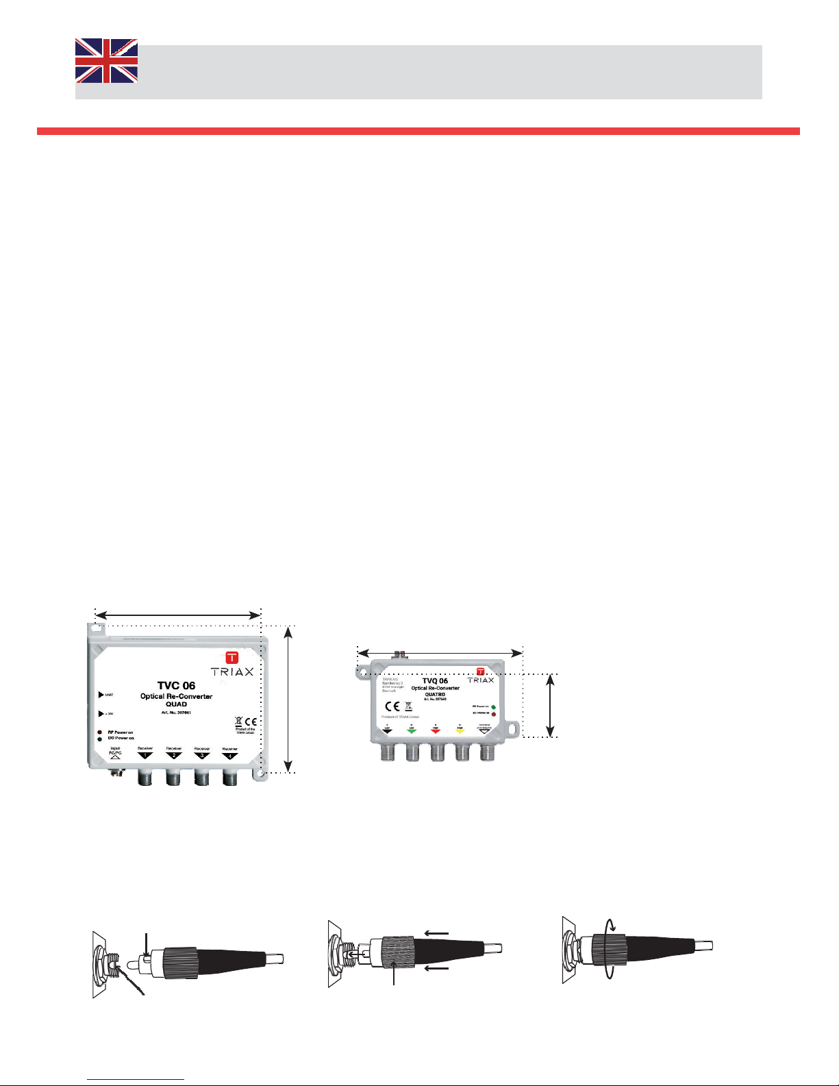
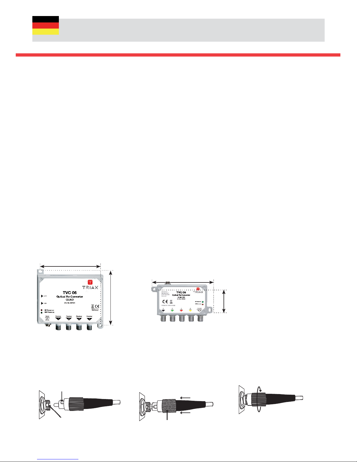
Montage
Le modu e se fixe directement sur e mur ou sur une p atine de montage à ’aide de vis 4mm.
LED ”Orange”
indique a présence
de signa RF
LED ”Verte”
indique a
présence de
’a imentation
Branchez a fibre équipée FC/PC sur ’entrée optique
(assurez-vous de a propreté et de ’a ignement des connecteurs).
A ignez e connecteur FC-PC
comme indiqué. Poussez
fermement.
1
Répère d’a ignement
Guide d’a ignement
Assurez-vous du positionnnement du
connec-
teur avant de verroui er e
connecteur (Fig. 3).
Poussez fermement orsque es
repères sont a ignés.
Ecrou
Remarque: un montage non conforme
occasionne une perte de signa .
3
Verroui er e connecteur
6/8
Attention : a vision directe dans une fibre a imentée par un signa optique est dangereuse et peut
provoquer
une cécité.
Récepteurs optiques QUAD & QUATRO - Manuel d’installation
115 mm
115 mm
105
mm
42,5
mm

Uti isez un mesureur de champ ou un ana yseur de spectre pour contrô er e signa de sortie RF ou sate ite. Les
modu es Quad et Quatro peuvent être té éa imentés par e mesureur.
Connectez ensuite e réseau coaxia (directement vers es prises usagers our vers un réseau de distribution commuté).
Le modu e TVC 06 est té é-a imenté par e STB, de même e modu e TVQ 06 par e commutateur. Une a imentation
externe n’est donc pas nécessaire.
Une a imentation externe PSU TPS 323 (307657) est disponib e orsqu’aucune source de té é-a imentation n’est disponib e.
Important:
Un termina doub e tuner devra être connecté sur es ports de sortie 1 & 2 OU 3 & 4 du modu e TVC 06 QUAD ; aucune
autre combinaison n’est autorisée.
Lorsque tous es branchements sont réa isés, verifier e fonctionnement du
système. A a mise sous tension, e modu e nécessite 10 secondes pour une auto-
ca ibration.
Type
Références
TVC 06
307641
TVQ 06
307640
Système
Quad + RF
Quatro + terrestrica
for the use with mu ti
-
switches
Entrée optique
Source TOL 32 / TOL 64 or TOU 232
dBm
-
12…0 /
-
1
3,5
…0
Longueurs d’ondes optiques
nm
1310 / 1550
Bande de frequences vertica
GHz
0.95
–
3.0
Bande
de frequences horizonta
GHz
3.4
–
5.45
Bande de frequences DVB
-
T
MHz
470...854
Bande de frequences DAB
MHz
174...241
Bande de frequences DTT
MHz
88...108
Connnectique d’entrée
FC/PC
Sorties BIS
Bande Horizonta Haute (convertie de 4.4 à 5.45 GHz)
MHz
1100
-
2150, > 15,5 V 22 kHz
Fixe
Bande Vertica Haute (convertie de 1.95 to 3.0 GHz)
MHz
1100
-
2150, < 14,5 V 22 kHz
Fixe
Bande Horizonta Basse (convertie de 3.4 to 4.4 GHz)
MHz
950
-
1950, > 15,5 V
Fixe
Bande Vertica Basse (convertie de 0.95 to 1.95 GHz)
MHz
950
-
1950, < 14,5 V
Fixe
Impédance, nomina e
Ohm
75
75
Adaptation (min.)
dB
10
10
Contrô e de gain automatique(AGC)
dB
30
30
Niveau de sortie SAT
commutab e
dBµV
ca. 75
ca. 79
/74/69
Sorties RF
Bande de frequences terrestre, DVB
-
T
MHz
470...854
470...854
Bande de frequences
terrestre, DAB
MHz
174...240
174...240
Bande de frequences terrestre, DTT
MHz
87...108
87...108
Niveau de sortie RF
dBµV
ca. 65
ca. 75
Caractéristiques généra es
Connecteurs de sortie
4 x F (4 x SAT/TER)
5 x F (4xSAT+1xTER)
Consommation
mA
125 @ 20V; 225 @ 10V
<400 @ 20V
Tension d’entrée
V
10...20
10...20
Depuis e récepteur SAT
Depuis e commutateur
Température d’entrée
°C
-
15...+60
-
15...+60
Poids
kg
0,8
0,8
Dimensions L x H x P
mm
128 x 94 x 27
97 x 61 x 26
Accessoires
A imentation externe TPS 323 PSU
(à commander séparement)
TPS 323 PSU (100-240 VAC +20VDC/1.2A), Référence 307657
7/8

07-2017
Copyright © Triax
A/S
Contact
triax.com/contact
triax.com
This manual suits for next models
1
Table of contents
Languages:
Other Triax Media Converter manuals