Tricel NOVO EN6-50 User manual

Technical & Installation Manual
Tricel®Wastewater treatment systems
TTM T106 Rev 06 Nov 13

2
Table of contents
1. Health and safety precautions: ...................................................................................................................... 3
1.1 General: ..................................................................................................................................................................................3
1.2 Electrical/Maintenance:......................................................................................................................................................3
1.3 Installation:............................................................................................................................................................................4
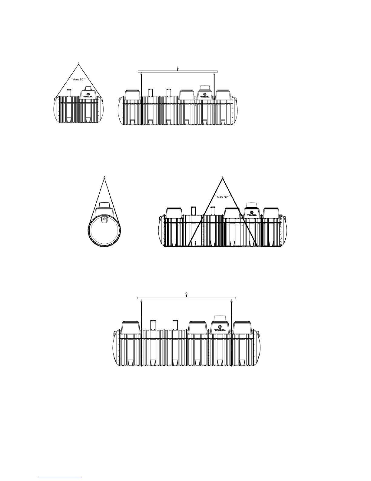
2. Transportation, unloading and storage of tanks: ........................................................................................... 4
3. Introduction:.................................................................................................................................................. 6
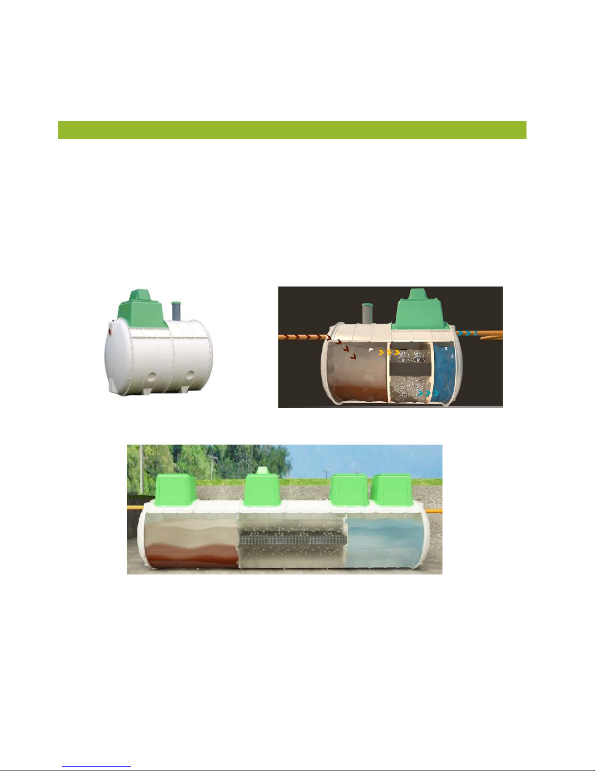
4. The wastewater purification process:............................................................................................................ 7
4.1 Stage 1: Primary settlement chamber:............................................................................................................................7
4.2 Stage 2: Aeration (treatment) chamber: .........................................................................................................................7
4.3 Stage 3: Final settlement chamber: .................................................................................................................................7
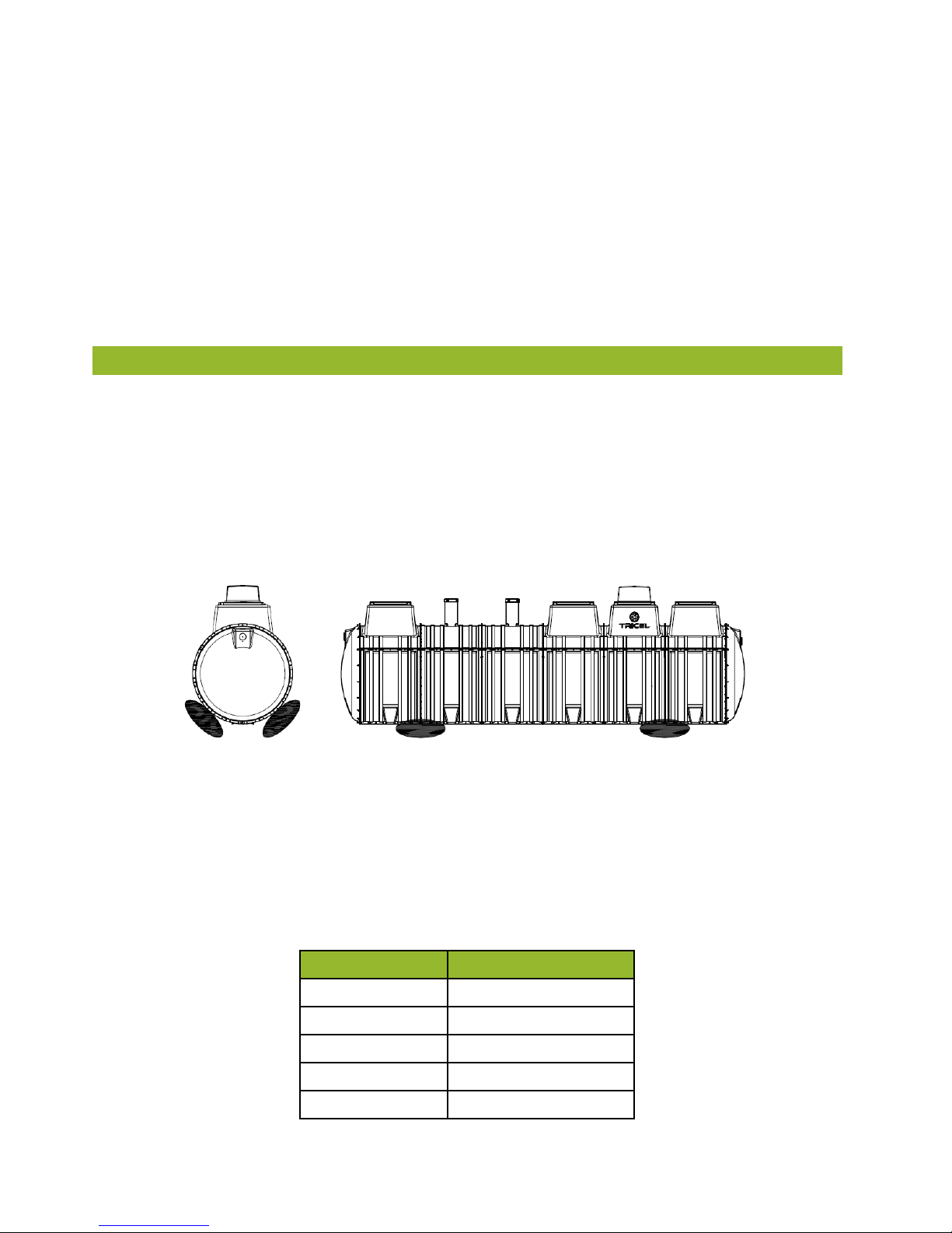
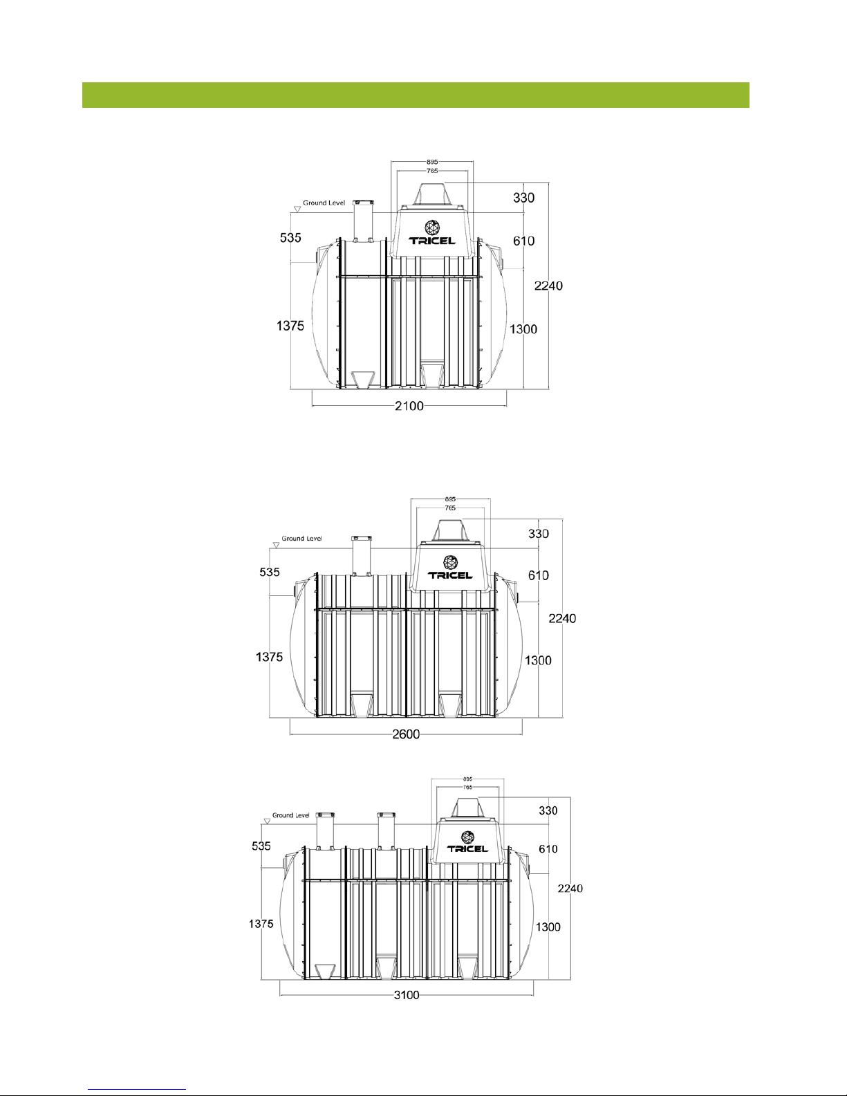
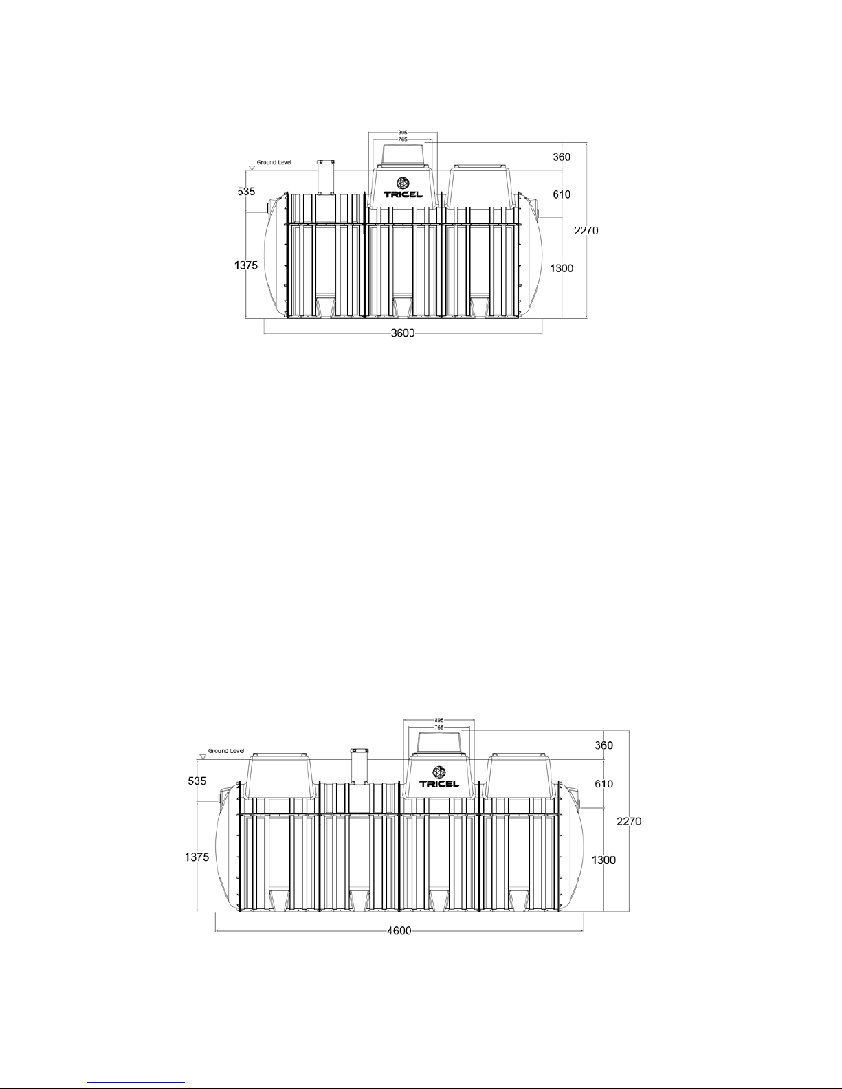
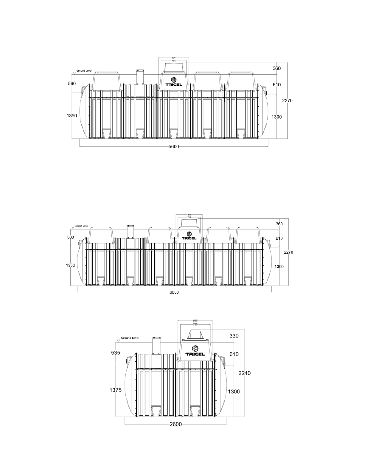
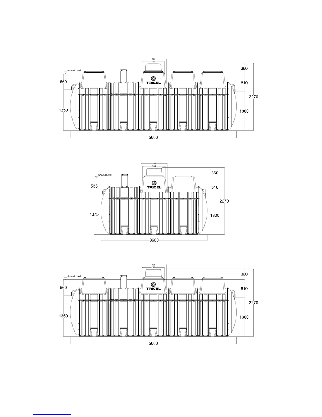
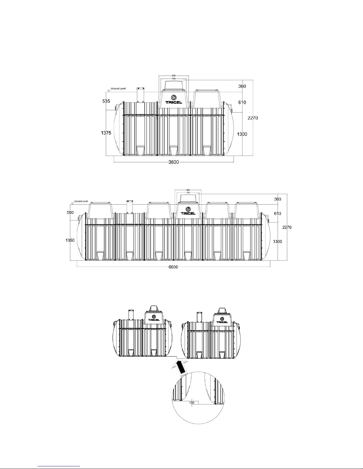
5. Plant Dimensions:.......................................................................................................................................... 8
6. Plant Drawings:............................................................................................................................................ 10
7. Technical drawing of Tricel pumped plant: ................................................................................................. 15
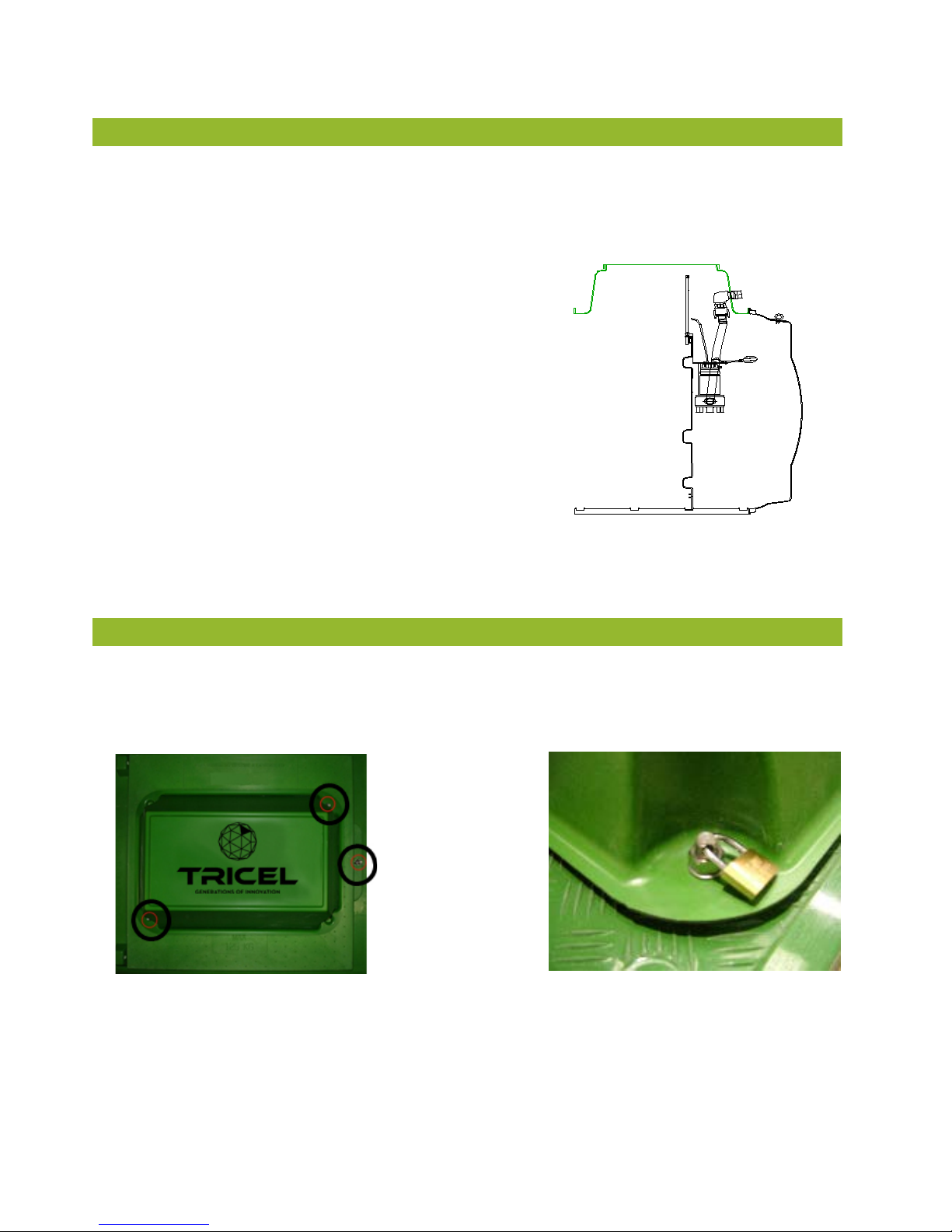
8. Lid locking points:........................................................................................................................................ 15
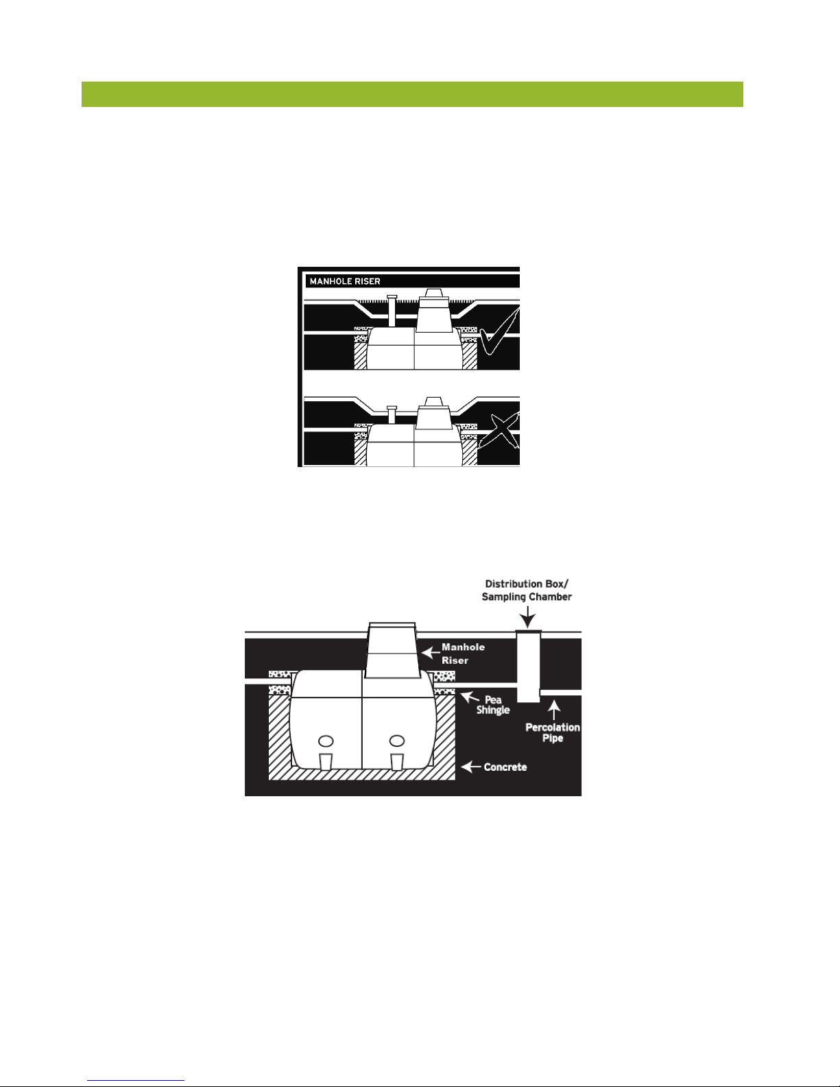
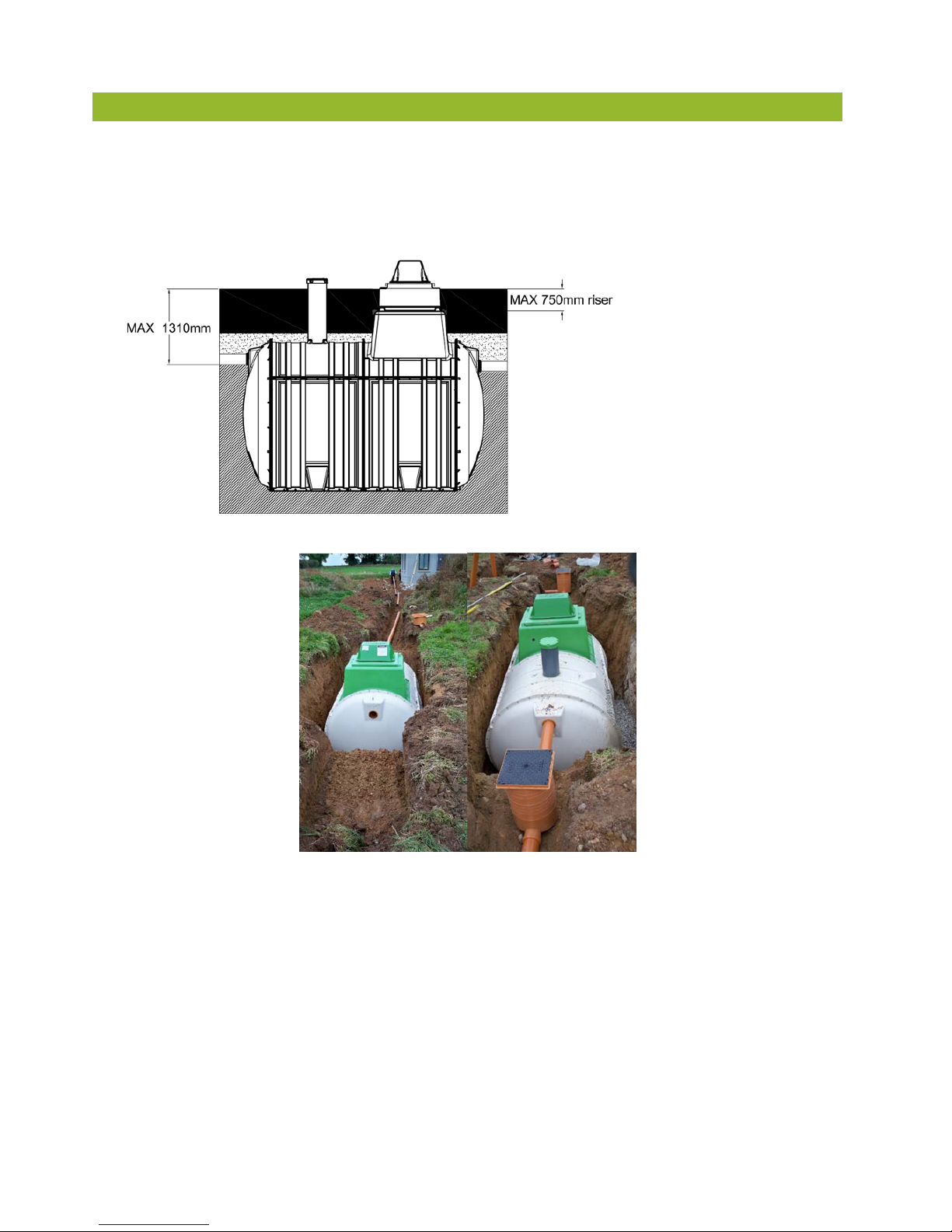
9. Manhole risers – (deep inverts): .................................................................................................................. 16
10. Installation: ................................................................................................................................................. 17
10.1 Pre –installation tank inspection: ............................................................................................................................... 17
10.2 Quick installation guidelines:...................................................................................................................................... 18
10.3 Detailed installation information:.............................................................................................................................. 20
10.4 Gravel installation:......................................................................................................................................................... 23
10.5 Concrete installation: .................................................................................................................................................... 24
10.6 Plinth and Backfill specifications: .............................................................................................................................. 25
11. Electrical installation:.................................................................................................................................. 27
12. Plumbing the plant: ..................................................................................................................................... 27
13. Ancillary installation notes:......................................................................................................................... 28
13.1 Ventilation:....................................................................................................................................................................... 28
13.2 Control housings:............................................................................................................................................................ 28
13.3 Access:............................................................................................................................................................................... 29
14. Plant operation: ........................................................................................................................................... 29
15. Disposal of treated water: ........................................................................................................................... 29
16. Maintenance: ............................................................................................................................................... 30
16.1 Regular maintenance:.................................................................................................................................................... 30
16.2 Yearly maintenance: ...................................................................................................................................................... 30
16.3 Production of sludge: .................................................................................................................................................... 31
17. Operating conditions: .................................................................................................................................. 31
18. Troubleshooting: ......................................................................................................................................... 33
TTM T106 Rev 09 – 28 Mar 2014

3
It is important to read the full technical and installation guide prior to installation. This document should be
retained for the lifetime of the product and in the event of change of ownership be transferred to the new
owner.
Precaution
Prior to installation, please consider finished garden level when installing the plant. If you envisage that a
manhole riser/extension may be required to ensure manhole lid remains above finished ground level, the plant
must be installed with the appropriate excavation foundation and backfill to accommodate the riser. Please refer
to page 16 for manhole riser details.
1. Health and safety precautions:
As safety and security are of vital importance, the following aspects are critical.
1.1 General:
•Ensure that all the information contained in this manual is adhered to at all times
•Treated wastewater is not suitable for human consumption.
•It’s important that locks are fitted to the lid to prevent accidental access.
•Manholes are rated to 125kg and are for pedestrian use only
•Never enter a tank, unless qualified to do so.
•Naked flames shall not be used in the vicinity of the tank due to the danger of combustion.
•The manhole covers shall never be left off an unattended tank. Always lock the cover of the plant
when work is completed
•Sewage and sewage effluent can carry micro-organisms and gases harmful to human health. Any
person carrying out work on the plant must be appropriately trained. Suitable protective clothing;
including gloves, goggles should be worn at all times. Always remove contaminated clothing and
protective equipment after working with sewage treatment plants. Wash hands and face prior to
eating, drinking or smoking.
1.2 Electrical/Maintenance:
•All electrical work to be carried out by competent persons using suitable materials for the
application.
•Do not open the Tricel®Novo cover without firstly isolating the mains power
•Electrical work must be carried out strictly to the manufacturer’s instructions and to the relevant
national rules for electrical installations.
•When working with machinery / electrical equipment, proximity of water shall be noted. Electrical
equipment shall not be wet when working with it.
•There is potential danger when de-sludging and therefore this shall never be done alone.

4
1.3 Installation:
•Excavation work should be planned with due regard to health and safety requirements.
•Excavation should either be shored or battered back to a “safe” angle
•Use appropriate lifting equipment
•Care should be taken around grounds work machinery
•Keep proper footing and balance at all time
1.Transportation, unloading and storage of tanks:
1. Tanks must be held down during transportation using nylon straps, do not use cables or chains to secure
tanks. Do not over tighten straps to cause deformation of the tank shell. Do not drop or roll tanks from the
truck.
2. Move tanks only by lifting and setting, do not drag or roll.
3. Always set the tank(s) on flat smooth ground free from debris etc. To prevent movement, tanks may need to
be tied down and chocked.
4. Tanks are best lifted by a machine and webbing lifting straps – do not use chains or wire ropes in contact
with the tank. Ensure tank is empty when lifting. Care is needed to control the lift to ensure the tank is not
damaged.
5. Tanks from one to four modules (4.6m) in length should be lifted using the eyebolts on the tank.
60o when lifting the tank. To ensure the angle is not greater than 60othe following sling lengths are required:
Length of tank Minimum length of sling
2.1 2.1
2.6 2.6
3.1 3.1
3.6 3.6
4.6 4.6

5
Ensure sufficient lifting height can be achieved and is available on site. If not a lifting bar as per option 2 is
required.
Option 1* Option 2*
6. Tanks which are greater than 4 modules (4.6m) in length should be lifted using the slings provided as per
option 3, shown below.
Option 3*
Ensure sufficient lifting height can be achieved and is available on site. If not a lifting bar as per option 4 is
required.
Option 4*
Ensure the slings are positioned at a joint on the tank, firmly secured and the load is evenly balanced.
*Typical lifting examples

6
1. Introduction:
Tricel Novo wastewater treatment plants are manufactured from Sheet Molding Compound (SMC) ensuring a
durable and strong product. The Tricel Novo is manufactured in modular components and these modules are
fabricated together to make different size tanks.
The Tricel Novo Submerged aeration plant is suitable for domestic and light commercial applications. These
plants use a simple proven technology, comprising of 3 treatment zones. In each zone a different stage of the
treatment occurs. Wastewater from the dwelling, toilets, sinks, shower etc., enters the plant and the purification
process begins.

7
1.The wastewater purification process:
4.1 Stage 1: Primary settlement chamber:
The wastewater is introduced into the primary chamber. The large volume of this chamber reduces velocity
of the wastewater. This along with the long flow path allow the wastewater maximum time in the first
chamber resulting in a higher settlement rate. Settlement occurs when the heavier solids, drop out of the
wastewater and settle to the bottom of the tank to create sludge and when lighter solids, like fats or oils,
float to the top of the water to create a scum. Up to 70% of the solids are removed in Primary settlement
zone. Anaerobic breakdown begins to occur and improve the water quality. A baffling system holds
the sludge and scum in the primary settlement zone and allow wastewaters to move into the aeration zone.
The large sludge storage volume increases the de-sludging intervals.
4.2 Stage 2: Aeration (treatment) chamber:
Stage 2 takes place in the aeration chamber where submerged aeration combines the principles of the bio
film and activated sludge processes. Masses of naturally occurring bacteria inhabit specially designed
plastic filter media. The filter media, has large surface area, and is supported within the aeration zone. As
the liquid flows slowly through the filter media the bacteria feed on the waste removing them from the
liquid. These bacteria are sustained with air, which is continuously supplied from a purpose built low
pressure, high volume air compressor in the top section of the unit. The air is delivered through a diffused
aeration system, which break the air into bubbles as they are dispersed through the aeration zone. The
continuous circulation of the wastewater within the aeration zone means that the wastewater is passed
through the filter media over and over, thus ensuring very high treatment efficiency. The purified liquid is
then passed into the final settlement zone.
4.3 Stage 3: Final settlement chamber:
As the liquid flows from the aeration zone into the final settlement zone small quantities of bacteria may be
carried with the liquid. Before discharge from the plant, these solids must be separated from the liquid. With
the velocity of the liquid slowed down and the flow path maximised the bacteria settles to the bottom of
the tank, like sludge, through the up flow nature of the zone. A sludge return system pumps this sludge
back to the primary settlement zone. The remaining treated liquid now meets the required standard to be
safely passed out of the Tricel Novo plant.

8
1. Plant Dimensions:
Tricel Novo wastewater treatment plants, certified to EN 12566-3:2005
Design population UK6 UK8 UK10 UK12 UK18 UK24 UK30
Nominal inlet/outlet pipe
diameter mm 110 110 110 110 110 150 150
Overall length m 2.1 2.6 3.1 3.6 4.6 5.6 6.6
Overall width m 1.64 1.64 1.64 1.64 1.64 1.64 1.64
Overall height m 2.24 2.24 2.24 2.27 2.27 2.27 2.27
Inlet invert to base m 1.375 1.375 1.375 1.375 1.375 1.35 1.35
Outlet invert to base m 1.3 1.3 1.3 1.3 1.3 1.3 1.3
Inlet invert to ground level m 0.535 0.535 0.535 0.535 0.535 0.56 0.56
Outlet invert to ground level m 0.61 0.61 0.61 0.61 0.61 0.61 0.61
Height above ground level m 0.33 0.33 0.33 0.36 0.36 0.36 0.36
Weight empty** kg 275 375 350 400 500 600 700
BOD Load kg/day 0.36 0.48 0.6 0.72 1.08 1.44 1.8
Air blower rating (mean) watts 60 100 100 100 200 200 200+60
Desludge period (minimum)*** months 12 12 12 12 9 8 6
Thickness (minimum) mm 5 5 5 5 5 5 5
Retention time hours 80 80 76.8 74 63.8 58.7 55.6
** Allow 100kgs for lifting purposes
*** Depending on use

9
Design population UK36 * UK42* UK50*
Plant A Plant B Plant A Plant B Plant A Plant B
Nominal inlet/outlet pipe diameter
mm 150 150 150 150 150 150
Overall length m 2.6 5.6 3.6 5.6 3.6 6.6
Overall width m 1.64 1.64 1.64 1.64 1.64 1.64
Overall height m 1.99 2.27 1.99 2.27 1.99 2.27
Inlet invert to base m 1.35 1.35 1.35 1.35 1.35 1.35
Outlet invert to base m 1.3 1.3 1.3 1.3 1.3 1.3
Inlet invert to ground level m 0.46 0.56 0.46 0.56 0.46 0.56
Outlet Invert to ground level m 0.51 0.61 0.51 0.61 0.51 0.61
Height above ground level m 0.18 0.36 0.18 0.36 0.18 0.36
Weight empty** kg 300 600 400 600 400 700
BOD load kg/day 2.16 2.52 3
Air blower rating (mean) watts 200+80 200 x 2 200 x 2
Desludge period (minimum)*** months 12 12 12
Thickness (minimum) mm 5 5 5
Retention time hours 56.5 54.6 51.1
*Plants may require a stepped foundation, with “Tank B” lower than “Tank A” by 100mm approx.
** Allow 100kgs for lifting purposes
*** Depending on use

10
1. Plant Drawings:
Tricel Novo UK6 gravity plant:
Tricel Novo UK8 gravity plant:
Tricel Novo UK10 gravity plant:

11
Tricel Novo UK12 gravity plant:
Tricel Novo UK18 gravity plant:

12
Tricel Novo UK24 gravity plant:
Tricel Novo UK30 gravity plant:
Tricel Novo UK36 gravity plant – 2 tank plant:

13
Tricel Novo UK42 gravity plant – 2 tank plant:

14
Tricel Novo UK50 gravity plant 2 tank plant:
Example of “stepped installation”.

15
1. Technical drawing of Tricel pumped plant:
All plants are available as pumped options. The pump is housed in the final settlement chamber of each plant.
Other pump options are available to customer specifications.
Pump Specification
•Min discharge rate 60l/min
•Continuous duty with 35°C liquids & fully submerged
•Dry motor (class F insulation)
•IP68 protection
•Max immersion 5m
•Single phase 220-240 V 50 Hz 2 poles
•0.55 to 1.1 kW for single phase
•Rp 1 ½” delivery port (female gas)
•Handles solids up to 35mm
FINAL
SETTLEMENT
TANKS
1. Lid locking points:
All manholes should be locked for safety. Tanks are supplied with 3 optional locking points, as seen above. All
these points should be locked with a suitable locking device to prevent unauthorised access. Locking devices not
supplied.

16
1. Manhole risers – (deep inverts):
Manhole risers are available for deeper installation requirements
250mm manhole risers require installation suitable for the site condition.
500mm* & 750mm* manhole risers require a complete concrete installation – See section 10.5.
Max manhole riser is 750mm
Never place the covers of the
tank below ground level.
Do not allow ground water
enter the plant
Only a Tricel Novo manhole
risers should be used
Manhole risers are available
as standard
250mm
500mm
750mm
*Plants with a manhole riser of 500mm or 750mm must have a concrete installation. 500mm and 750mm risers
cannot be retrofitted unless the correct installation is in place.

17
1. Installation:
All installations must be “fit for purpose” to suit the on-site conditions, which will vary from site to site.
This is the responsibility of the onsite contractor.
The Tricel Novo is suitable for a maximum manhole riser of 750mm which gives a maximum inlet invert of
1310mm, as per picture. The Tricel Novo is not suitable where a deeper installation is required.
10.1 Pre –installation tank inspection:
•Tanks should be visually inspected for fractures to shell or ribs, de laminations, scratches or
abrasions deeper than 1.5m prior to installation. Any damage should be notified to the delivery
driver and/or to your supplier. Do not attempt to carry out any un-authorised repairs, as this will
invalidate the warranty on the tank
•Once the tank has been installed, we cannot accept any claims for damage

18
10.2 Quick installation guidelines:
A dry site is one where the water table never rises higher than the base of the Tricel Novo plant.
A wet Site is one where the water table may rise higher than the base of the Tricel Novo plant.
The plant should never be installed where ground water can rise higher than the inlet pipe.
Important
Inlet invert to finished ground level must be determined to ensure the correct installation procedure is
followed. See section 9.
Guidelines Dry Site Wet Site
The tank should be located as far away from the dwelling as is
practically possible considering topography and pipe work levels.
Separation distances must meet all National and Local regulations. The
tank location should be specified by a suitably qualified person. The
plant must be installed correctly to ensure surface or ground water
does not enter the plant.
Never roll the tank. Tanks shall be lifted into position in accordance
with supplier’s instructions. See section 2
Dig a hole 500mm larger than the plant dimensions in plan. The depth
of the hole will be determined by the inlet pipe level.
If the plant contains more than one tank a stepped installation is
required
Remove any soft spots or boulders of significant size from the base or
sides of the excavation.
Ground water must be pumped to give a dry excavation and excavation
lined with polythene.
Determine the type of backfill by taking into account, ground
conditions (wet or dry) and finished ground level (determine if and
type of0 risers required). The site engineer should specify the site
conditions.
A base is then formed using compacted gravel and this must be flat and
level.
A base is constructed of a 50mm layer of compacted gravel covered
with a 250mm layer of 25n semi dry concrete.
Ensure gravel/concrete is clean and contains no large materials.

19
Lift tank into position and align height for connecting pipe work.
Ensure correct inlet and outlet orientations of the plant, which may
contain 1 or more tanks.
Ensure that each tank is 100% level.
Connect pipe work, as required.
Ballast the tank with water. Refer to detailed installation
Commence gravel backfilling in 300mm layers approximately up to
50mm over the cylindrical body of the tank, ensuring tank and any pipe
work is properly supported.
Commence concrete backfilling in 300mm layers approximately up to
the pipe work level, ensuring tank and any pipe work is properly
supported.
Continue backfilling with gravel up to 50mm over the cylindrical body
of the tank
Mount and seal any turret extensions.
Complete backfilling with topsoil up to the max ground level line
indicated on the plant. The surrounding finished ground level should
never be higher than the “max ground level line”.
Compact evenly around the tanks to ensure it’s is properly supported.
An access chamber should be installed before and after the tank for
sampling and to assist in clearing possible blockages
If sewage consists of high quantities of grease a grease trap should be
installed prior to the plant.
Note: The option of a reinforced concrete slabs or deadman anchor may also be used on wet sites. This
should be designed by an on-site structural engineer to suit site conditions.

20
10.3 Detailed installation information:
The Tricel Novo must be situated a minimum of 7m from the dwelling and as far away as practically
possible considering topography and pipe work levels. The Tricel Novo should not be installed in an area
subject to flooding or excessive water runoff. The area around the Tricel Novo should be adequately
drained, to permanently remove ground water and surface water from the proximity of the tank. The Tricel
Novo system is not suitable to be used in water logged sites, where the ground water may rise above the
inlet level.
10.3.1 Excavation size:
Suitably sized equipment will be required to excavate the hole and to lift the plant into place.
Installation depends on on-site conditions, water, slopes, location etc. Excavation should be planned with
due regard to health and safety requirements, and should be either shored or battered back to a “safe”
angle. The excavation should allow a minimum 250mm clearance between the tank and the excavation
wall or face of shoring. A minimum of 500mm is also required between adjacent tanks. Unstable ground
with excessive sand, peat swamps etc. may require larger excavations. The excavation should be
maintained dry by pumping or whatever suitable means.
Total excavation: {Width. + 500mm} x {Length + 500mm}
Excavation depth:
Dry Site: Allow 250mm for tank base/plinth.
Wet Site: Allow 300mm for tank base/plinth
Table of contents
Popular Water System manuals by other brands

Clean Logix
Clean Logix PBX-CAB-DOS user manual

BIO-MICROBICS
BIO-MICROBICS MicroFAST 0.5 installation manual

Pure Water
Pure Water WATT'R TWIN Owners and installation manual

Greenlife
Greenlife Biovitor Installation and maintenance instructions

Little Giant
Little Giant WCR Series owner's manual

Zip
Zip HydroTap G4 installation instructions

ProMinent
ProMinent Dulcodes D operating instructions

AutoAqua
AutoAqua Smart ASOV manual

Wayne
Wayne SWS Series Operating instructions and parts manual

EINHELL
EINHELL GC-WW 8042 ECO Original operating instructions

Wilo
Wilo Isar BOOST5 Installation and operating instructions

Galmet
Galmet KSG21 Premium GT Installation and operation manual