Trick-tools BGB - 2.5 User manual

-1 -
IOM-B-120225
HardCore Belt Grinder
Installation and Operation Manual
for models;
BGB – 2.5
BGB - 4.0
BGB – 6.0
IMPORTANT !!!!
It is the responsibility of the owner of this product to
ensure that the user will read and comply with the
provisions of this manual, which is intended to be an
integral part of your HardCore belt grinder. As
operation of this powertool can be hazardous, and even
cause serious personal injury, this manual should be
kept with the machine at all times for reference by the
user, each time prior to use.

-2 -
DANGER !!!!
This machine MUST be securely fastened to a suitable
work bench, or floor mounted pedestal, prior to
operation. In addition, proper work attire (which
complies with all applicable federal and / or state laws
and regulations) must be worn at all times while
operating this machine.
This includes;
1. Proper eye and/or face protective gear
2. Proper respiratory protection
3. Proper hand and body protection (i.e. leather work
gloves and apron in order to prevent any article of
clothing from becoming entangled in the moving
parts of the equipment)
Failure to comply with the above
requirements can result in
SERIOUS personal injury!

- 3 -
NOTE:
The following instructions refer to the two attached
illustrations for component identification.
Preparation;
1. After unpacking, mount the motor assembly to a
suitable floor mounted pedestal or work bench.
(provided fasteners may not be adequate)
Initial Setup;
1. Rotate the beam assy. to the vertical position by
loosening the pivot lock screw.
2. Tighten the pivot lock screw to secure the beam.
3. Remove the idler wheel screw from the idler
support, leaving the spring in place.
4. Install the idler guard, making sure that the idler
guard screws (2) align with the recesses in the idler
support for proper orientation and spacing.
5. Re-install the idler wheel screw through the idler
guard & into the idler support about 2 turns.
6. Install the platen mount assy. to the beam leaving
the screws (4) slightly loose for platen adjustment.
7. Install the idler wheel assembly and tighten the
idler wheel screw with a 3/16 in. allen wrench.
8. Install the workrest arm assy. onto the contact
support, making sure it is up against the shoulder.

- 4 -
9. Remove the nut & washer from the contact shaft.
10. Install the contact wheel (inside marked), washer,
and nut. Tighten the contact nut (15/16” socket or
wrench) by depressing the spring-loaded wheel
lock button and rotating the contact wheel until
full engagement of the wheel lock is felt. After
tightening, release the wheel lock button.
11. Using a straight-edge, align the platen with the
tangents of the center portions of the contact and
idler wheels and tighten the mount screws (4).
12. Install the remaining platen screws (2).
13. Install the belt guard standoffs (2) to the beam.
14. Rotate the take-up lever to the “release” position
(towards the motor) and install the desired
grinding belt over the center of the idler and
contact wheels. Rotate the take-up lever to the
“lock” position (away from the motor, until the
over-center stop is felt) in order to proceed with
initial belt tensioning.
15. Adjust for the desired belt tension by rotating the
tension knob clockwise (from top) to increase, or
counter-clockwise to decrease. Adequate tension is
required for the belt to “track” properly. Rotate
the idler wheel by hand to make sure that the belt
is not tracking too far off of the idler and contact
wheels.
16. Attach the belt guard to the standoffs using the
wing screws (2).
17. Adjust the belt guard guide so that the guide
engages the hole in the guard, up against the
washer, and tighten the jam nut against the beam.

- 5 -
18. Verify that both the “Power” and “Run” switches
are in the “OFF” position (down) and connect the
power cable to a properly grounded outlet.
19. Turn the “Power” switch to “ON”. This switch
enables the motor drive functions (on / off,
acceleration, deceleration, etc.). The “Power”
indicating lamp (red) will turn on. During this
“stand-by” period the motor drive will be using
power equivalent to a 20 watt light bulb. Although
this is satisfactory for periods when the motor is
not running (accessory changes, belt changes, etc.)
the “Power” switch should be turned “OFF” when
the grinder is not in use for longer periods of time,
in order to conserve energy. When attempting to
rotate the contact wheel during “stand-by” a slight
resistance will be evident.
20. Set the “Speed” control knob to about 20%. The
attached belt speed chart correlates the speed
control settings to actual belt speed (SFM).
21. Briefly turn the “Run” switch to “ON” to start the
motor and ensure reasonable belt tracking. If the
belt tracks evenly with the contact wheel, the motor
can be left running for the next step.
22. While the motor is running, rotate the track knob
to position the belt in the desired location on the
contact wheel.
NOTE:
Excessive tracking adjustments may require slight
belt tension adjustments with the tension knob.

- 6 -
23. Turn the “Run” switch to “OFF” and wait for all
motion to stop.
24. Attach the workrest assembly to the workrest arm
assembly and adjust as required.
Operational Instructions;
1. The beam can be re-positioned by loosening the
pivot lock screw.
DANGER
Never loosen the pivot lock while the grinder is running.
NOTE:
Always support the beam when loosening the pivot lock
screw. The pivot drag screw (located opposite of the
pivot lock screw) can be adjusted to provide adequate
friction while the pivot lock is loosened.
2. Re-tighten the pivot lock.
3. When belt changes are required, the belt can easily
be removed by turning the “Run” switch to “OFF”
(allowing all motion to stop) and removing the belt
guard.
4. Rotate the take-up lever to the “release” position
and remove the belt.
5. Install the new belt and rotate the take-up lever to
the “lock” position. Tension may vary between
different belts.

- 7 -
6. Replace the belt guard.
7. Turn the “Run” switch to “ON” and adjust for
proper tracking, if necessary.
8. The contact wheel can be removed / replaced by
first removing the belt guard & grinding belt, then
depressing the spring-loaded wheel lock button and
rotating the contact wheel until full engagement of
the wheel lock is felt. After breaking the contact
nut loose, release the wheel lock button.
9. Install the replacement contact wheel (inside is
marked), washer, and nut. Tighten the contact nut
by depressing the wheel lock button and rotating
the contact wheel until full engagement of the
wheel lock is felt. After tightening, release the
wheel lock button.
DO NOT OVER_TIGHTEN!
WARNING
Never attempt to use the wheel lock as a “braking”
device while the machine is running as damage to the
internal parts WILL occur.
10. Re-install the grinding belt and belt guard.
-End of procedure-

-1 -
PM-B-120225
HardCore Belt Grinder
Packing Instructions
for models;
BGB - 6.0
BGB - 4.0
BGB - 2.5

- 2 -
1. Remove the Wing Screws (2) & Belt Guard. Bag &
label the Wing Screws.
2. Remove the Workrest Assy.
3. Remove the Idler Wheel Assy.
4. Remove the Contact Wheel.
5. Bag & label the Contact Nut & Washer.
6. Remove the Workrest Arm Assy.
7. Remove the Belt Guard Guide (3 pcs), bag & label.
8. Remove the Belt Guard Standoffs (2).
9. Remove the inside Platen Screws (2), bag & label.
10. Remove the Platen Mount Screws (4) & Platen
Mount, bag & label the Platen Mount Screws.
11. Remove the Idler Guard.
12. Replace the Idler Wheel Screw.
-End of procedure-

-1 -
SM-B-120225
HardCore Belt Grinder
Service Manual for models;
BGB – 2.5
BGB – 4.0
BGB – 6.0
DANGER !!!!
Be sure that the grinder is un-plugged
from the wall power source prior to any
disassembly / assembly
NOTE:
Before proceeding with the following procedure it is
imperative that the operator fully understands the
installation / operation manual

- 2 -
Fastener / Hardware Abbreviations;
DP Dowel Pin
FHSC Flat Head Socket Cap screw
FW-NAS640 Flat Washer – Mil Spec
FW-NAS1140 Flat Washer – Mil Spec
FW-NEO Flat Washer – Neoprene
FW-TFE Flat Washer – Teflon
FW-USS Flat Washer – US Standard
HCS Hex Cap Screw
HN Hex Nut
HN-EL Hex Nut – Elastic Lock
HN-J Hex Nut – Jam
HN-ML-T Hex Nut – Mech. Lock - Thin
LW-S Lock Washer – Split
SHCS Socket Head Cap Screw
SSS Socket Set Screw
NOTE:
The following instructions refer to the attached
illustrations for component identification.
Figures 6 thru 8 are for reference only.

- 3 -
Disassembly Instructions
1. Position the beam at about 45 degrees.
2. Remove the workrest assembly. (Fig. 5)
3. Remove the wing screws (2) and belt guard.
4. Remove the grinding belt.
5. Remove the contact wheel nut & washer.
6. Remove the contact wheel.
7. Remove the belt guard standoffs (2).
8. Remove the belt guard guide w/nut & washer.
9. Remove the platen screws (4 or 8) & platen.
10. Remove the workrest arm assembly. (Fig. 4)
11. Remove the platen mount screws (4) & mount.
12. Loosen the idler wheel screw (3/16 allen) and
remove the idler wheel assembly.
13. Remove the idler wheel screw.
14. Back-off the idler guard screws (2) two turns and
remove the idler guard.
15. Remove the idler seal spring and idler seal plate
(with idler seal) from the idler support.
16. Remove the tension knob screw by holding the
knob with a strap wrench and turning the screw
counter-clockwise (from top) with a 5/16 in. allen
wrench.
17. Loosen the tension knob by holding the knob with
a strap wrench and turning the tension bushing
clockwise with a 3/8 in. allen wrench, and remove.
18. Remove the tension knob spring, tension seal
retainer, & tension knob seal.
19. Remove the take-up lever screw and remove the
take-up lever and take-up shaft seal.

- 4 -
20. Position the beam horizontally.
21. Remove the cap plugs (2) from the beam. (Fig. 3)
22. Use a 9/16 in. socket to loosen the drive belt tension
nuts (2) just until belt tension is released. (Fig. 1)
23. Remove the 1/4 in. (10) and 5/16 in. (2) beam
screws. (Fig. 3) The outside beam should remain in
place, supported by dowel pins.
24. Carefully remove the outside beam assembly,
making sure to keep the tension slide assembly
attached to the inside beam. The drive belt is also
disengaged at this time.
25. Rotate the track knob until the tension bushing can
just be removed from the tension slide assembly.
26. Remove the tension slide assembly by lifting the
tension shaft off of the take-up shaft assy. and out,
in order to disengage the slide from the track stud.
27. Remove the take-up shaft assembly.
28. Remove the track stud from the track knob. (Fig.1)
29. Remove the retaining ring from the track knob.
30. Remove the track knob & washer.
31. Remove the wheel lock assy. (special tool required)
32. Remove the drive belt tension nuts (2), lock
washers (2), and flat washers (2).
33. Remove the inside beam from the motor pivot.
34. Remove the pivot lock screw, lock washer, and flat
washer.
35. Remove the pivot drag screw, lock washer, and flat
washer.
36. Remove the motor pivot from the motor.
37. Remove the set screws (2) from the motor sheave.

- 5 -
38. Remove the motor sheave from the motor shaft.
(gear puller required)
39. Remove the key from the motor shaft.
40. Remove the contact sheave nut by holding the
sheave with a strap wrench. (Fig. 2)
41. Remove the flat washer, sheave, & woodruff key.
42. Remove the screws (3) and remove the contact
shaft assembly from the outside beam.
- End of Procedure -

- 6 -
Assembly Instructions
Note:
Be sure to observe where lubrication (grease) is
required as shown in the illustrations.
1. Place the motor pivot onto the motor (studs level)
and attach the pivot lock screw, lock washer, and
flat washer, into the threaded motor hole at the
10:00 position. (Fig. 1)
2. Attach the pivot drag screw, lock washer, and flat
washer at the 4:00 position.
3. Place the motor sheave and drive key onto the
motor shaft.
4. Tighten the motor sheave set screws (2) securely so
that the distance from the motor pivot face to the
outside of the sheave is 1.275 inches.
5. Place the inside beam onto the motor pivot studs
and attach new drive belt tension flat washers, lock
washers, and nuts. (Light snug only as beam must
be able to slide)
6. Attach the track knob & washer to the inside beam
and secure with the retaining ring.
7. Thread the track stud into the track knob about 2
turns, aligning the flats with the long axis of the
inside beam.
8. Check that the wheel lock is properly attached to
the inside beam.
9. Install the dowel pins (2) onto the inside beam.
10. Position the beam horizontally.

- 7 -
11. Place the contact support assy. into the outside
beam & tighten the fasteners (3). (Fig. 2)
12. Install the woodruff key, contact sheave, flat
washer, and new lock nut.
13. Tighten the lock nut by holding the sheave with a
strap wrench, then verify freedom of rotation.
14. Place the take-up shaft assy. into the bushing of the
inside beam & rotate counter-clockwise. (Fig. 3)
15. Place the tension slide assy. t-slot onto the track
stud and position the slide dowel pins into the slots
on the inside beam. (It may be necessary to lift the
tension shaft over the take-up shaft assy. bearing)
16. Place the tension bushing onto the tension shaft.
17. Rotate the track knob until the tension slide is
parallel with the inside beam, taking care to engage
the tension bushing correctly with the beam.
18. Position the drive belt onto the motor sheave so
that the belt remains inside of the beam cavity.
19. While maintaining tension on the drive belt, install
the outside beam assy. making sure that the contact
sheave is fully engaged and centered with the belt.
This is best achieved by “hanging” the outside
beam over the idler support, then pulling the far
end of the belt out of the inside beam (slightly) in
order to position it over the contact sheave.
20. Maintaining tension on the belt, slide the inside
beam so that the dowel pins engage and the beams
come together. The tension slide and take-up shaft
will also align with the outside beam at this time.

- 8 -
21. Continue to maintain belt tension and separate the
beams slightly. Rotate the contact shaft to visually
ensure correct drive belt alignment.
22. Push the beams back together and rotate the beam
to a vertical position, which will provide some drive
belt tension.
23. Install and tighten the 1/4 in. (10) & the lower of
the 5/16 in. beam screws.
24. Start the upper 5/16 in. beam screw 2 turns.
25. From the front side of the grinder, position a lever
(a long screwdriver will work) on top of the head of
the 5/16 in. screw & underneath the rear of the
motor pivot, up against the inside beam. Adjust
the drive belt tension by applying force in the
appropriate direction and tightening the upper belt
tension nut.
26. Rotate the contact shaft by hand to ensure that the
drive belt is tensioned and aligned correctly. (Belt
tension can be verified by reaching into the cap
plug hole on the outside beam with your finger)
27. Re-tighten both drive belt tension nuts securely.
28. Tighten the remaining 5/16 in. beam screw.
29. Connect the power source and turn on the motor.
Check that there are no vibrations or rumbling in
order to verify correct assembly to this point.
30. Turn off the motor and remove the power source.
31. Install the cap plugs (2) into the outside beam.
32. Place the tension seal retainer (with tension knob
seal) and tension knob spring onto the tension
bushing. (Fig. 4)

- 9 -
33. Install the tension knob and tighten (holding the
knob with a strap wrench) by turning the bushing
counter-clockwise with a 3/8 in. allen wrench.
34. Install the tension knob screw and tighten (holding
the knob with a strap wrench) by turning the screw
clockwise with a 5/16 in. allen wrench.
35. Attach the take-up lever (with seal) to the take-up
shaft so that the lever is parallel with the long axis
of the beam (when in the “lock” position) and
tighten the screw.
36. Place the idler seal plate (with seal) and idler seal
spring onto the idler support.
37. Install the idler guard, making sure that the set
screws (2) align with the recesses in the idler
support for proper orientation and spacing.
38. Install the idler wheel screw through the idler
guard & into the idler support about 2 turns.
39. Install the platen mount to the beam leaving the
screws (4) slightly loose for platen adjustment.
40. Install the platen to the platen mount, leaving the 2
inside screws for later.
41. Install the idler wheel assembly and tighten the
idler wheel screw with a 3/16 in. allen wrench.
42. Install the workrest arm assy. onto the contact
support, making sure it is up against the shoulder.
43. Install the contact wheel, washer, and nut.
44. Using a straight-edge, align the platen with the
tangents of the center portions of the contact and
idler wheels and tighten the mount screws (4).
45. Install the remaining platen screws (2).
46. Install the belt guard standoffs (2) to the beam.

- 10 -
47. Install the belt guard guide w/nut & washer,
leaving about 1 in. from the beam to the outside.
48. Install the desired grinding belt.
49. Adjust for the desired belt tension.
50. Attach the belt guard to the standoffs using the
wing screws (2).
51. Adjust the belt guard guide so that the guide
engages the hole in the guard, up against the
washer, and tighten the jam nut against the beam.
52. Attach the workrest assembly to the workrest arm
assembly and adjust as required.
- End of Procedure -
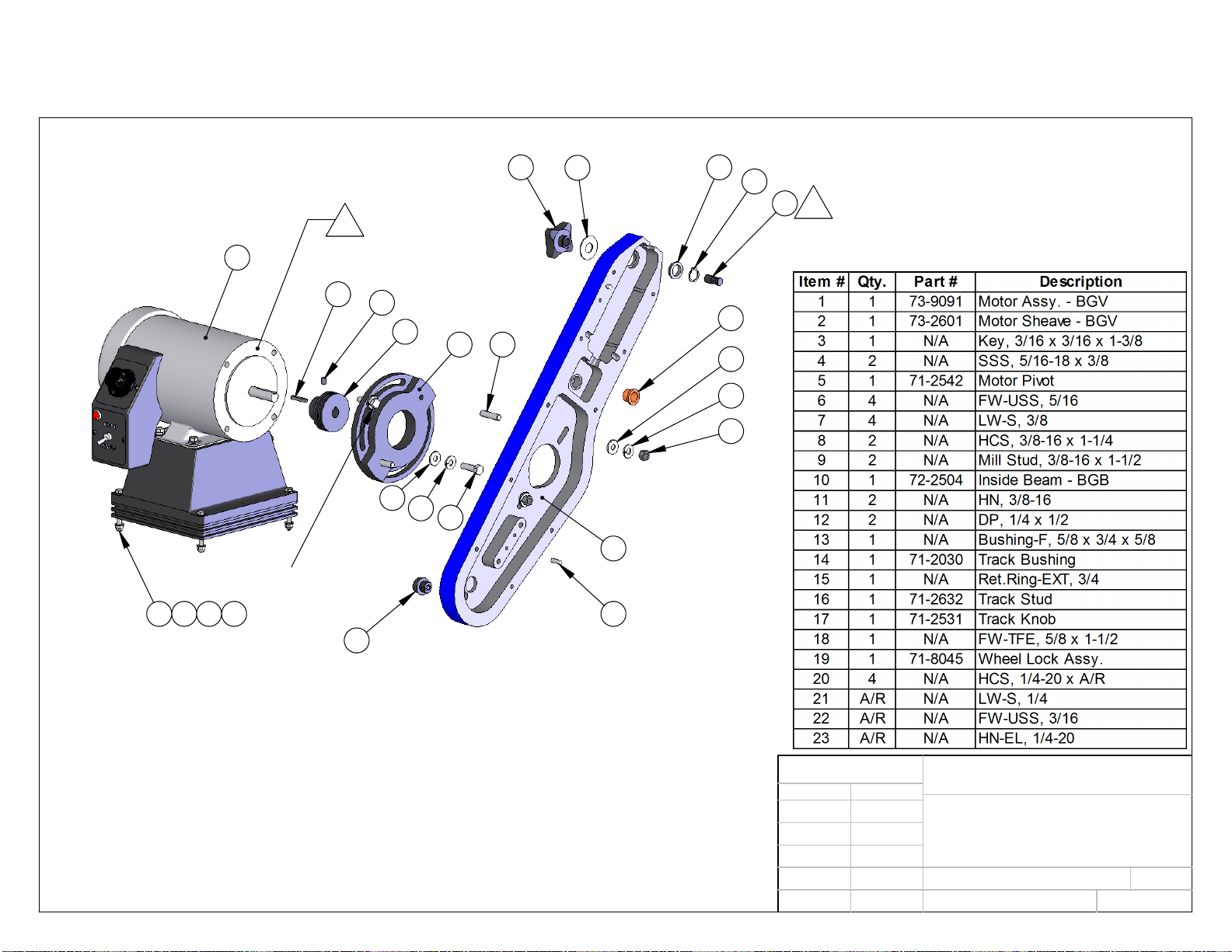
1
2
4
3
5
678
9
10
6
7
11
12
13
14 15
16
18
17
19
20 21 22 23
G
face only
drive belt
tension nut
pivot lock
screw
pivot drag
screw
G
threads only
Figure 1
REV:
PART NO:
DATE
Q/A:
MFG:
ENG:
CHK:
DRW:
APPROVALS
CAD GENERATED DRAWING,
DO NOT MANUALLY UPDATE
SHEET:
1 of 1
A
02-25-12
MH
00-0000
INSIDE BEAM ASSEMBLY
BGB-2.5 (4.0 & 6.0) - SM
Assy,Inside Beam-2.5-BGB-mda-X
HardCore Products
CAD FILE:
This manual suits for next models
2


 Handling instructions")


