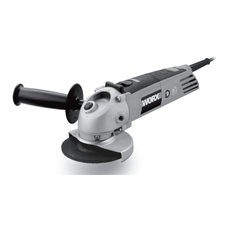
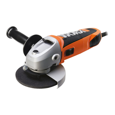
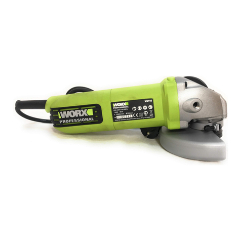
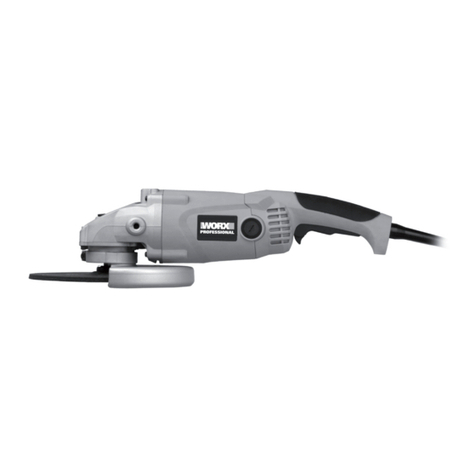
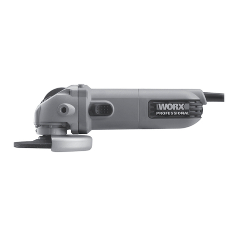
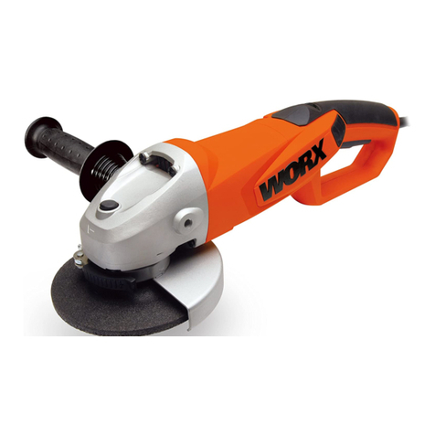
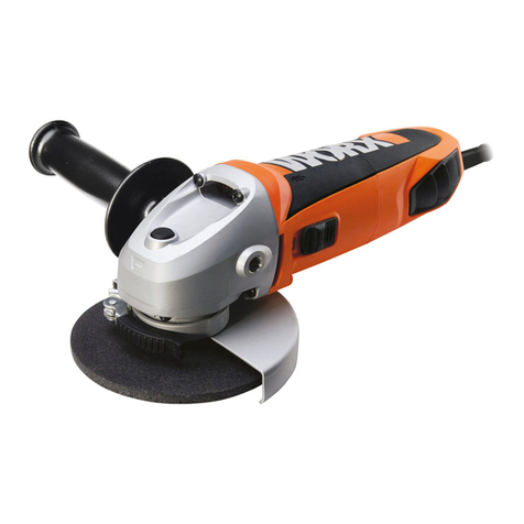
Worx WU707 User manual

ANGLE GRINDER
Angle grinder
Winkelschleifer
Meuleuse d’angle
Smerigliatrice angolare
Amoladora angular
Rebarbadora
Haakse slijpmachine
•
•
•
•
•
•
•
Vinkelsliber
Kulmahiomakone
Vinkelsliper
Vinkelslip
Açı öğütücü
Γωνιακός τροχός
Угловая шлифовальная машина
•
•
•
•
•
•
•
EN 05
D 16
F 27
I 39
ES 51
PT 63
NL 75
DK 87
FIN 98
NOR 109
SV 120
TR 131
GR 142
RU 1 5 5
WU707 WU707.1 WU708 WU708.1 WU709
WU709.1 WU721 WU721.1 WU722 WU722.1

Original instructions
Übersetzung der Originalanleitung
Traduction des instructions initiales
Traduzione delle istruzioni originali
Traducción de las instrucciones originales
Tradução das instruções originais
Vertaling van de oorspronkelijke instructies
•
•
•
•
•
•
•
•
•
•
•
•
•
•
EN
D
F
I
ES
PT
NL
DK
FIN
NOR
SV
TR
GR
RU
Oversættelse af de oprindelige instruktioner
Alkuperäisten ohjeiden käännös
Oversettelse av de opprinnelige instruksjonene
Översättning av originalinstruktionerna
Asıl talimatların çevirisi
Μετάφραση των πρωτότυπων οδηγιών
Перевод исходных инструкций

1 2
13
3
4
685
10
11
9 7
12 14
4
9
3
1
C.1
C.2
BA
FE
DC

!

5
1
2
3
4
5
6
7
8
9
10
11
12
13
14
Component list
On-off switch
Hand grip area
Auxiliary handle
Spindle lock button
Outer flange
Inner flange
Spindle
Grinding disc *
Spanner
Protection guard for grinding
Clamping lever
Coded projection
Variable speed control selector (WU709 709.1 WU722 722.1)
Protection guard for cutting *
* Not all the accessories illustrated or described are included in
standard delivery.
Noise information
WU707 WU707.1 WU708 WU708.1 WU721 WU721.1
A weighted sound pressure 88.5dB(A)
A weighted sound power 99.5dB(A)
KPA&KWA 3.0dB(A)
Wear ear protection when sound pressure is over 80dB(A)
Technical data
WU707
WU707.1
WU708
WU708.1
WU709
WU709.1
WU721
WU721.1
WU722
WU722.1
Voltage 220-240V~50/60Hz
Power input 850W 1050W
Rated speed 12000/min 2800-12000
/min 12000/min 2800-12000
/min
Protection class /II
Spindle thread M14
Disc size 115mm 125mm 125mm 125mm 125mm
Disc bore 22.2mm
Machine weight 1.7kg
•
•
•
•
•
•
•
•
•
•
•
•

6
WU709 WU709.1 WU722 WU722.1
A weighted sound pressure 89.7dB(A)
A weighted sound power 102.7dB(A)
KPA&KWA 3.0dB(A)
Wear ear protection when sound pressure is over 80dB(A)
Vibration information
WU707 WU707.1 WU708 WU708.1 WU721 WU721.1
Vibration total values (triax vector sum) determined according to
EN 60745:
Typical weighted vibration
Vibration emission value
ah=6.90m/s2
Uncertainty K=1.5m/s²
WU709 WU709.1 WU722 WU722.1
Vibration total values (triax vector sum) determined according to
EN 60745:
Typical weighted vibration
Vibration emission value
ah=7.99m/s2
Uncertainty K=1.5m/s²
Warning: The vibration emission value during actual use of the
power tool can differ from the declared value depending on the ways
in which the tool is used dependant on the following examples and
other variations on how the tool is used:
•
•
•
•
How the tool is used and the materials being cut.
The tool being in good condition and well maintained
The use the correct accessory for the tool and ensuring it is sharp and
in good condition.
The tightness of the grip on the handles and if any anti vibration
accessories are used.
And the tool is being used as intended by its design and these
instructions.
This tool may cause hand-arm vibration syndrome if its use is
not adequately managed
Warning: To be accurate, an estimation of exposure level in the
actual conditions of use should also take account of all parts of the
operating cycle such as the times when the tool is switched off
and when it is running idle but not actually doing the job. This may
significantly reduce the exposure level over the total working period.
Helping to minimize your vibration exposure risk.
Maintain this tool in accordance with these instructions and keep well
lubricated (where appropriate).
If the tool is to be used regularly then invest in anti vibration
accessories.
Avoid using tools in temperatures of 100C or less.
Plan your work schedule to spread any high vibration tool use across
a number of days.
•
•
•
•

7
1
2
3
4
5
6
Additional safety points for your
angle grinder
SAFETY WARNINGS COMMON FOR GRINDING OR ABRASIVE
CUTTING-OFF OPERATIONS:
This power tool is intended to function as a grinder, or cut-off
tool. Read all safety warnings, instructions, illustrations and
specifications provided with this power tool. Failure to follow
all instructions listed below may result in electric shock, fire and/or
serious injury.
Operations such as sanding, wire brushing, polishing are not
recommended to be performed with this power tool. Operations
for which the power tool was not designed may create a hazard and
cause personal injury.
Do not use accessories which are not specifically designed
and recommended by the tool manufacturer. Just because the
accessory can be attached to your power tool, it does not assure safe
operation.
The rated speed of the accessory must be at least equal to the
maximum speed marked on the power tool. Accessories running
faster than their rated speed can break and fly apart.
The outside diameter and the thickness of your accessory must
be within the capacity rating of your power tool. Incorrectly sized
accessories cannot be adequately guarded or controlled.
The arbour size of wheels, flanges, backing pads or any other
accessory must properly fit the spindle of the power tool.
Accessories with arbour holes that do not match the mounting
hardware of the power tool will run out of balance, vibrate excessively
and may cause loss of control.
•
•
Accessories/qty.
WU707
WU707.1 WU708
WU708.1 WU709
WU709.1 WU721
WU721.1 WU722
WU722.1
Spanner 11111
Auxiliary
handle 11 (anti-
vibration) 1 (anti-
vibration) 1 (anti-
vibration) 1 (anti-
vibration)
We recommend that you purchase your accessories from the same
store that sold you the tool. Use good quality accessories marked
with a well-known brand name. Choose the type according to the
work you intend to undertake. Refer to the accessory packaging for
further details. Store personnel can assist you and offer advice.

8
7
8
9
10
11
Do not use a damaged accessory. Before each use inspect
the accessory such as abrasive wheels for chips and cracks,
backing pad for cracks, tear or excess wear. If power tool
or accessory is dropped, inspect for damage or install an
undamaged accessory. After inspecting and installing an
accessory, position yourself and bystanders away from the
plane of the rotating accessory and run the power tool at
maximum no-load speed for one minute. Damaged accessories
will normally break apart during this test time.
Wear personal protective equipment. Depending on
application, use face shield, safety goggles or safety glasses.
As appropriate, wear dust mask, hearing protectors, gloves
and workshop apron capable of stopping small abrasive or
workpiece fragments. The eye protection must be capable of
stopping flying debris generated by various operations . The dust
mask or respirator must be capable of filtrating particles generated by
your operation. Prolonged exposure to high intensity noise may cause
hearing loss.
Keep bystanders a safe distance away from work area.
Anyone entering the work area must wear personal protective
equipment. Fragments of workpiece or of a broken accessory may
fly away and cause injury beyond immediate area of operation.
Hold power tool by insulated gripping surfaces only, when
performing an operation where the cutting accessory may
contact hidden wiring or its own cord. Cutting accessory
contacting a “live” wire may make exposed metal parts of the power
tool “live” and shock the operator.
Position the cord clear of the spinning accessory. If you lose
control, the cord may be cut or snagged and your hand or arm may be
pulled into the spinning accessory.
Never lay the power tool down until the accessory has come to
a complete stop. The spinning accessory may grab the surface and
pull the power tool out of your control.
Do not run the power tool while carrying it at your side.
Accidental contact with the spinning accessory could snag your
clothing, pulling the accessory into your body.
Regularly clean the power tool’s air vents. The motor’s fan will
draw the dust inside the housing and excessive accumulation of
powdered metal may cause electrical hazards.
Do not operate the power tool near flammable materials.
Sparks could ignite these materials.
Do not use accessories that require liquid coolants. Using water
or other liquid coolants may result in electrocution or shock.
Your hand must hold on the handle when you are working. Always
use the auxiliary handles supplied with the tool. Loss of control can
cause personal injury
FURTHER SAFETY INSTRUCTIONS FOR ALL OPERATIONS
KICKBACK AND RELATED WARNINGS
Kickback is a sudden reaction to a pinched or snagged rotating wheel,
backing pad, brush or any other accessory. Pinching or snagging
causes rapid stalling of the rotating accessory which in turn causes
the uncontrolled power tool to be forced in the direction opposite of
the accessory’s rotation at the point of the binding.
For example, if an abrasive wheel is snagged or pinched by the
workpiece, the edge of the wheel that is entering into the pinch point
can dig into the surface of the material causing the wheel to climb
out or kick out. The wheel may either jump toward or away from
the operator, depending on direction of the wheel’s movement at
the point of pinching. Abrasive wheels may also break under these
12
13
14
15
16
17
9
conditions.
Kickback is the result of power tool misuse and/or incorrect operating
procedures or conditions and can be avoided by taking proper
precautions as given below.
Maintain a firm grip on the power tool and position your
body and arm to allow you to resist kickback forces. Always
use auxiliary handle, if provided, for maximum control over
kickback or torque reaction during start-up. The operator can
control torque reactions or kickback forces, if proper precautions are
taken.
Never place your hand near the rotating accessory. Accessory
may kickback over your hand.
Do not position your body in the area where power tool will
move if kickback occurs. Kickback will propel the tool in direction
opposite to the wheel’s movement at the point of snagging.
Use special care when working corners, sharp edges etc. Avoid
bouncing and snagging the accessory. Corners, sharp edges or
bouncing have a tendency to snag the rotating accessory and cause
loss of control or kickback.
Do not attach a saw chain woodcarving blade or toothed saw
blade. Such blades create frequent kickback and loss of control.
ADDITIONAL SAFETY INSTRUCTIONS FOR GRINDING AND
CUTTING-OFF OPERATIONS
SAFETY WARNINGS SPECIFIC FOR GRINDING AND ABRASIVE
CUTTING-OFF OPERATIONS:
Use only wheel types that are recommended for your power
tool and the specific guard designed for the selected wheel.
Wheels for which the power tool was not designed cannot be
adequately guarded and are unsafe.
2
3
4
5
1
2
3
The guard must be securely attached to the power tool and
positioned for maximum safety, so the least amount of wheel is
exposed towards the operator. The guard helps to protect operator
from broken wheel fragments and accidental contact with wheel.
Wheels must be used only for recommended applications. For
example: do not grind with the side of cut-off wheel. Abrasive
cut-off wheels are intended for peripheral grinding, side forces
applied to these wheels may cause them to shatter.
Always use undamaged wheel flanges that are of correct size
and shape for your selected wheel. Proper wheel flanges support
the wheel thus reducing the possibility of wheel breakage. Flanges
for cut-off wheels may be different from grinding wheel flanges.
Do not use worn down wheels from larger power tools. Wheel
intended for larger power tool is not suitable for the higher speed of a
smaller tool and may burst.
ADDITIONAL SAFETY INSTRUCTIONS FOR CUTTING-OFF
OPERATIONS
ADDITIONAL SAFETY WARNINGS SPECIFIC FOR ABRASIVE
CUTTING-OFF OPERATIONS:
Do not “jam” the cut-off wheel or apply excessive pressure. Do
not attempt to make an excessive depth of cut. Overstressing
the wheel increases the loading and susceptibility to twisting or
binding of the wheel in the cut and the possibility of kickback or
wheel breakage.
Do not position your body in line with and behind the rotating
wheel. When the wheel, at the point of operation, is moving away
from your body, the possible kickback may propel the spinning wheel
and the power tool directly at you.
When wheel is binding or when interrupting a cut for any
1
2
3
4
5
1

10
4
5
6
reason, switch off the power tool and hold the power tool
motionless until the wheel comes to a complete stop. Never
attempt to remove the cut-off wheel from the cut while the
wheel is in motion otherwise kickback may occur. Investigate
and take corrective action to eliminate the cause of wheel binding.
Do not restart the cutting operation in the workpiece. Let the
wheel reach full speed and carefully reenter the cut. The wheel
may bind, walk up or kickback if the power tool is restarted in the
workpiece.
Support panels or any oversized workpiece to minimize the
risk of wheel pinching and kickback. Large workpieces tend to
sag under their own weight. Supports must be placed under the
workpiece near the line of cut and near the edge of the workpiece on
both sides of the wheel.
Use extra caution when making a “pocket cut” into existing
walls or other blind areas. The protruding wheel may cut gas or
water pipes, electrical wiring or objects that can cause kickback.
Symbols
To reduce the risk of injury, user must read instruction manual
Warning
Wear eye protection
Wear dust mask
Wear ear protection
Double insulation
Waste electrical products should not be disposed of with
household waste. Please recycle where facilities exist. Check
with your Local Authority or retailer for recycling advice.

11
1
Intended use
Note: Before using the tool, read the instruction book carefully.
The machine is intended for cutting, roughing and brushing metal
and stone materials without using water. For cutting stone, a cutting
guide is required.
Assembly and adjustment
MOUNTING THE PROTECTIVE DEVICES
AUXILIARY HANDLE
For all work with the machine, the auxiliary handle (3) must be
mounted.
Screw the auxiliary handle (3) on the right or left of the machine head
depending on the working method. (See A)
Vibration-dampening Auxiliary Handle (WU708/WU708.1/
WU709/WU709.1/WU721/WU721.1/WU722/WU722.1)
The vibration-dampening auxiliary handle reduces the vibrations,
making operation more comfortable and secure.
Do not make any alterations to the auxiliary handle.
Do not continue to use an auxiliary handle if it is damaged.
MOUNTING THE GRINDING TOOLS
Before any work on the machine itself, pull the mains plug.
Grinding and cutting discs become very hot while working; do
not touch until they have cooled.
SPINDLE LOCK BUTTON
Clean the grinder spindle and all parts to be mounted. For clamping
and loosening the grinding tools, lock the grinder spindle (7) with the
spindle lock button (4).
Actuate the spindle lock button (4) only when the grinder
spindle is at a standstill!
GRINDING/CUTTING DISC
Pay attention to the dimensions of the grinding disc. The
mounting hole diameter must fit the inner flange (6) without
play. Do not use reducers or adapters.
When using a diamond cutting disc, take care that the direction-
of-rotation arrow on the diamond cutting disc and the direction of
rotation of the machine (direction-of-rotation arrow on the machine
head) agree.
For mounting, see the Component list illustration page.
Screw on the outer flange (5) and tighten with the two-pin spanner
(9). (See B)
ADJUSTABLE OUTER FLANGE CLAMPING
The outer flange (5) should be adjusted to suit different disc
thickness. For thinner cutting or diamond discs the raised part of the
outer flange is fitted facing away from the disc (See C.2). For thicker
grinding discs the raised part of the outer flange is fitted facing
towards the disc to provide improved support for the disc hole (See
C.1). Always ensure your disc is securely clamped.
ADJUSTING THE PROTECTION GUARD
Before any work on the machine itself, pull the mains plug.
For work with grinding or cutting discs, the protection guard
1
2
3

12
must be mounted.
The coded projection (12) on the protection guard (10/14) ensures
that only a guard that fits the machine type can be mounted.
Open the clamping lever (11). Place the protection guard (10/14) with
coded projection (12) into the coded groove on the spindle collar
of the machine head and rotate to the required position (working
position).
To fasten the protection guard (10/14), close the clamping lever (11).
The closed side of the protection guard (10/14) must always
point to the operator.
Operation
STARTING OPERATION
To start the power tool, push the on/off switch (1) forward.
To lock the on/off switch (1), press the on/off switch (1) down at the
front until it engages.
To switch off the power tool, release the on/off switch (1) or, if it is
locked, briefly push down the back of the on/off switch (1) and then
release it.
Soft start motor (WU721/WU721.1/WU722/WU722.1)
Internal electronic components allow the motor speed to increase
slowly, which reduces the“twisting”effect on your wrists due to the
high power motor.
Constant electronic control (WU721/WU721.1/WU722/
WU722.1)
Constant electronic control holds the speed constant at no-load and
under load, and ensures uniform working performance.
Overload protection (WU721/WU721.1/WU722/WU722.1)
When overloaded, the motor comes to a stop. Relieve the load on the
machine immediately and allow cooling for approx. 30 seconds at the
highest no-load speed.
Variable speed control switch (WU709/WU709.1/WU722/
WU722.1)
The variable speed selector (13) allows you to vary the speed of the
angle grinder enabling the optimum speed to be selected for various
uses and to avoid the workpiece being burnt, this can occur especially
when cross cutting. The speed increases as you turn the switch right
and decreases as turn left (1 being slowest and 6 fastest).
OPERATING INSTRUCTIONS
Clamp the workpiece if it does not remain stationary due to its own
weight.
Do not strain the machine so heavily that it comes to a standstill.
Grinding and cutting discs become very hot while working; do not
touch until they have cooled.
Pull the plug from the socket-outlet when not using the
machine. With the plug inserted and mains voltage existing, the
power tool still has low power consumption even when it switched
off.
HAND GRIP AREAS
Always hold your angle grinder firmly with both hands when
operating (See E).
•
•
•
•
1

13
ROUGH GRINDING
The best roughing results are achieved when setting the machine
at an angle of 30° to 40°. Move the machine back and forth with
moderate pressure. In this manner, the workpiece will not become
too hot, does not discolour and no grooves are formed.
Warning! Never use a cutting disc for roughing.
CUTTING
Warning! For cutting metal, always work with the wheel
guard for cutting.
When cutting, do not press, tilt or oscillate the machine. Work with
moderate feed, adapted to the material being cut.
Do not reduce the speed of running down cutting discs by applying
sideward pressure.
The direction in which the cutting is performed is important.
The machine must always work in an up-grinding motion. Therefore,
never move the machine in the other direction! Otherwise, the
danger exists of it being pushed uncontrolled out of the cut.
ROTATING THE GEAR CASE
Before any work on the machine itself, pull the mains plug, and
then remove the disc and guard
The gear case can be rotated with respect to the machine housing. In
this manner, the On/Off switch can be brought to an advantageous
handling position for special working situations.
Remove the 4 x screws from the gear case. Carefully rotate the gear
case in your desired direction but do NOT pull the gear case out of
the housing. If the gear case comes out of the housing the motor
carbon brushes will need replacing.
Screw in the screws again and tighten. (See F)
AUTO-STOP CARBON BRUSHES
When the resin insulating tip (15) inside the carbon brush (16) is
exposed to contact the commutator (14), it will automatically shut
off the motor. When this occurs, both carbon brushes should be
replaced. Keep the carbon brushes clean and free to slip in the
holders. Both carbon brushes should be replaced at the same time.
Use only identical carbon brushes. (See G)
Working hints for your angle grinder
If your power tool becomes too hot, run no load for 2-3 minutes to
cool the motor.
Never start your angle grinder with the disc/ accessory in contact with
the workpiece.
Always start at no load to achieve maximum speed then start working.
Do not force the disc to work faster, reducing the Disc’s moving speed
means longer working time.
When grinding, always work with a 30° to 40° angle between disc and
workpiece. Larger angles will cut ridges into the workpiece and affect
the surface finish. Move the angle grinder across and back and forth
over the workpiece.
When using a cutting disc never change the cutting angle otherwise
you will stall the disc and angle grinder motor or break the disc.
When cutting, only cut in the opposite direction to the disc rotation. If
you cut in the same direction as the disc rotation the disc may push
itself out of the cut slot.
When cutting very hard material best results can be achieved with a
diamond disc.
When using a diamond disc it will become very hot. If this happens
2
3

14
you will see a full ring of sparks around the rotating disc. Stop cutting
and allow to cool at no load speed for 2-3 minutes.
Always ensure the workpiece is firmly held or clamped to prevent
movement.
Maintenance
Remove the plug from the socket before carrying out any
adjustment, servicing or maintenance.
Your power tool requires no additional lubrication or maintenance.
There are no user serviceable parts in your power tool. Never use
water or chemical cleaners to clean your power tool. Wipe clean with
a dry cloth. Always store your power tool in a dry place. Keep the
motor ventilation slots clean. Keep all working controls free of dust.
Occasionally you may see sparks through the ventilation slots. This is
normal and will not damage your power tool.
If the supply cord is damaged, it must be replaced by the
manufacturer, its service agent or similarly qualified persons in order
to avoid a hazard.
Environmental protection
Waste electrical products should not be disposed of with
household waste. Please recycle where facilities exist. Check
with your local authorities or retailer for recycling advice.
Plug replacement
(UK & Ireland only)
If you need to replace the fitted plug then follow the instructions
below.
IMPORTANT
The wires in the mains lead are colored in accordance with the
following code:
BLUE =NEUTRAL BROWN = LIVE
As the colors of the wires in the mains lead of this appliance may not
correspond with the colored markings identifying the terminals in
your plug, proceed as follows. The wire which is colored blue must
be connected to the terminal which is marked with N. The wire which
is colored brown must be connected to the terminal which is marked
with L.
Note: If a moulded plug is fitted and has to be removed take great
care in disposing of the plug and severed cable, it must be destroyed
to prevent engaging into a socket.
Connect
Blue to N
(neutral)
Outer sleeve
firmly clamped
Cable grip
Brown L (live)
13 Amp fuse approved
to BS1362
Warning!
Never connect live
or neutral wires to
the earth terminal
of the plug. Only
fit an approved
13ABS1363/A plug
and the correct
rated fuse.

15
EC
DECLARATION OF CONFORMITY
We,
POSITEC Germany GmbH
Neuer Höltigbaum 6
22143 Hamburg
Declare that the product,
Description WORX Angle grinder
Type WU707 WU707.1 WU708 WU708.1 WU709 WU709.1 WU721
WU721.1 WU722 WU722.1
Complies with the following Directives,
EC Machinery Directive 98/37/EC (valid till Dec.28, 2009)
2006/42/EC (valid since Dec.29, 2009)
EC Low Voltage Directive 2006/95/EC
EC Electromagnetic Compatibility Directive 2004/108/EC
Standards conform to
EN 55014-1 EN 55014-2 EN 61000-3-2
EN 61000-3-3 EN 60745-1 EN 60745-2-3
The person authorized to compile the technical file,
Name Russell Nicholson
Address Positec Powertools(Europe) LTD
Pinewood, Chineham Bussiness Park,
Basingstoke, Hampshire, RG24 8AL, United Kingdom
2009/11/18
Jacky Zhou
POSITEC Quality Manager
•
•
•

16
1
2
3
4
5
6
7
8
9
10
11
12
13
14
Bedienteile
Ein-aus-schalter
Handgriffe
Zusatzhandgriff
Spindelstopp-taste
Aussen-flansch
Innen-flansch
Schleifspindel
Schleifscheibe *
Stift-schlüssel
Schleif-Schutzhaube
Spannhebel
Kodierklinke
Einstellrad drehzahl
Schutzhaube zum Trennen *
* Abgebildetes oder beschriebenes Zubehör gehört teilweise nicht
zum Lieferumfang
Informationen über lärm
WU707 WU707.1 WU708 WU708.1 WU721 WU721.1
Gewichteter Schalldruck 88.5dB(A)
Gewichtete Schallleistung 99.5dB(A)
KPA&KWA 3.0dB(A)
Tragen Sie bei einem Schalldruck über einen Gehörschutz 80dB(A)
Technische daten
Modell-
bezeichnung
WU707
WU707.1
WU708
WU708.1
WU709
WU709.1
WU721
WU721.1
WU722
WU722.1
Spannung 220-240V~50/60Hz
Nennaufnahme-
leistung 850W 1050W
Leerlaufdrehzahl 12000/min 2800-12000
/min 12000/min 2800-12000
/min
Schutzklasse /II
Schleifspindel-
gewinde M14
Scheiben-
Durchmesser 115mm 125mm 125mm 125mm 125mm
Scheiben-
bohrung 22.2mm
Gewicht 1.7kg
•
•
•
•
•
•
•
•
•
•
•
•

17
WU709 WU709.1 WU722 WU722.1
Gewichteter Schalldruck 89.7dB(A)
Gewichtete Schallleistung 102.7dB(A)
KPA&KWA 3.0dB(A)
Tragen Sie bei einem Schalldruck über einen Gehörschutz 80dB(A)
Informationen über vibrationen
WU707 WU707.1 WU708 WU708.1 WU721 WU721.1
Vibrationsgesamtmesswertermittlung gemäß EN 60745:
Typischer gewichteter
Vibrationswert
Vibrationsemissionswert
ah = 6.90m/s2
Unsicherheit K = 1.5m/s²
WU709 WU709.1 WU722 WU722.1
Vibrationsgesamtmesswertermittlung gemäß EN 60745:
Typischer gewichteter
Vibrationswert
Vibrationsemissionswert
ah= 7.99m/s2
Unsicherheit K = 1.5m/s²
WARNUNG: Der Vibrationsemissionswert während
des tatsächlichen Gebrauchs des Elektrowerkzeugs kann
vom angegebenen Wert abweichen, je nachdem, wie das
Werkzeug gemäß folgender Beispiele und anderweitiger
Verwendungsmöglichkeiten eingesetzt wird:
Wie das Werkzeug verwendet wird und Materialen geschnitten.
Das Werkzeug ist in gutem Zustand und gut gepflegt
Verwendung des richtigen Zubehörs für das Werkzeug und
Gewährleistung seiner Schärfe und seines guten Zustands.
Die Festigkeit der Handgriffe und ob Antivibrationszubehör
verwendet wird.
Und ob das verwendete Werkzeug dem Design und diesen
Anweisungen entsprechend verwendet wird.
Wird dieses Werkzeug nicht anemessen gehandhabt, kann es
ein Hand-Arm-Vibrationssyndrom erzeugen
WARNUNG: Um genau zu sein, sollte ein Abschätzung des
Belastungsgrades aller Arbeitsabschnitte während tatsächlicher
Verwendung berücksichtigt werden, z.B. die Zeiten, wenn das
Werkzeug ausgeschaltet ist, und wenn es sich im Leerlauf befindet
und eigentlich nicht eingesetzt wird. Auf diese Weise kann der
Belastungsgrad während der gesamten Arbeitszeit wesentlich
gemindert werden.
Minimieren Sie Ihr Risiko, dem Sie bei Vibrationen ausgesetzt sind.
Pflegen Sie dieses Werkzeug diesen Anweisungen entsprechend
und achten Sie auf eine gute Einfettung (wo erforderlich).
Bei regelmäßiger Verwendung dieses Werkzeugs sollten Sie in
Antivibrationszubehör investieren.
Vermeiden Sie den Einsatz von Werkzeugen bei Temperaturen von
•
•
•
•
•
•
•
•

18
•
•
•
10ºC oder darunter.
Machen Sie einen Arbeitsplan, um die Verwendung von hochvibrier-
enden Werkzeugen auf mehrere Tage zu verteilen.
Lieferumfang
WU707
WU707.1 WU708
WU708.1 WU709
WU709.1 WU721
WU721.1 WU722
WU722.1
Stift-Schlüssel 11111
Zusatzhandgriff
1
1 Antivibrations-
handgriff
1 Antivibrations-
handgriff
1 Antivibrations-
handgriff
1 Antivibrations-
handgriff
WU707.1 WU708.1 WU709.1 WU721.1 WU722.1
Werkzeugkoffer
11111
1
2
3
4
5
6
ZUSÄTZLICHE
SICHERHEITSHINWEISE FÜR
WINKELSCHLEIFER
GEMEINSAME WARNHINWEISE ZUM SCHLEIFEN,
TRENNSCHLEIFEN.:
Dieses Elektrowerkzeug ist zu verwenden als Schleifer,
Trennschleifmaschine. Beachten Sie alle Warnhinweise,
Anweisungen, Darstellungen und Daten, die Sie mit dem
Gerät erhalten. Wenn Sie die folgenden Anweisungen nicht
beachten, kann es zu elektrischem Schlag, Feuer und/oder schweren
Verletzungen kommen.
Dieses Elektrowerkzeug ist nicht geeignet zum
Sandpapierschleifen, Arbeiten mit Drahtbürsten, Polieren.
Verwendungen, für die das Elektrowerkzeug nicht vorgesehen ist,
können Gefährdungen und Verletzungen verursachen.
Verwenden Sie kein Zubehör, das vom Hersteller nicht speziell
für dieses Elektrowerkzeug vorgesehen und empfohlen wurde.
Nur weil Sie das Zubehör an Ihrem Elektrowerkzeug befestigen
können, garantiert das keine sichere Verwendung.
Die zulässige Drehzahl des Einsatzwerkzeugs muss mindestens
so hoch sein wie die auf dem Elektrowerkzeug angegebene
Höchstdrehzahl. Zubehör, das sich schneller als zulässig dreht, kann
zerstört werden.
Außendurchmesser und Dicke des Einsatzwerkzeugs müssen
den Maßangaben Ihres Elektrowerkzeugs entsprechen.
Falsch bemessene Einsatzwerkzeuge können nicht ausreichend
abgeschirmt oder kontrolliert werden.
Schleifscheiben, Flansche, Schleifteller oder anderes Zubehöhr

19
müssen genau auf die Schleifspindel Ihres Elektrowerkzeugs
passen. Einsatzwerkzeuge, die nicht genau auf die Schleifspindel
des Elektrowerkzeugs passen, drehen sich ungleichmäßig, vibrieren
sehr stark und können zum Verlust der Kontrolle führen.
Verwenden Sie keine beschädigten Einsatzwerkzeuge.
Kontrollieren Sie vor jeder Verwendung Einsatzwerkzeuge wie
Schleifscheiben auf Absplitterungen und Risse, Schleifteller
auf Risse, Verschleiß oder starke Abnutzung. Wenn das
Elektrowerkzeug oder das Einsatzwerkzeug herunterfällt,
überprüfen Sie, ob es beschädigt ist, oder verwenden
Sie ein unbeschädigtes Einsatzwerkzeug. Wenn Sie das
Einsatzwerkzeug kontrolliert und eingesetzt haben, halten
Sie und in der Nähe befindliche Personen sich außerhalb der
Ebene des rotierenden Einsatzwerkzeugs und lassen Sie das
Gerät eine Minute lang mit Höchstdrehzahl laufen. Beschädigte
Einsatzwerkzeuge brechen meist in dieser Testzeit.
Tragen Sie persönliche Schutzausrüstung. Verwenden Sie
je nach Anwendung Vollgesichtsschutz, Augenschutz oder
Schutzbrille. Soweit angemessen, tragen Sie Staubmaske,
Gehörschutz, Schutzhandschuhe oder Spezialschürze, die
kleine Schleif- und Materialpartikel von Ihnen fernhält. Die
Augen sollen vor herumfliegenden Fremdkörpern geschützt werden,
die bei verschiedenen Anwendungen entstehen. Staub- oder
Atemschutzmaske müssen den bei der Anwendung entstehenden
Staub filtern. Wenn Sie lange lautem Lärm ausgesetzt sind, können
Sie einen Hörverlust erleiden.
Achten Sie bei anderen Personen auf sicheren Abstand zu
Ihrem Arbeitsbereich. Jeder, der den Arbeitsbereich betritt,
muss persönliche Schutzausrüstung tragen. Bruchstücke des
Werkstücks oder gebrochener Einsatzwerkzeuge können wegfliegen
7
8
9
und Verletzungen auch außerhalb des direkten Arbeitsbereichs
verursachen.
Halten Sie das Gerät nur an den isolierten Griffflächen, wenn
Sie Arbeiten ausführen, bei denen das Einsatzwerkzeug
verborgene Stromleitungen oder das eigene Netzkabel treffen
kann. Der Kontakt mit einer spannungsführenden Leitung kann
auch metallene Geräteteile unter Spannung setzen und zu einem
elektrischen Schlag führen.
Halten Sie das Netzkabel von sich drehenden
Einsatzwerkzeugen fern. Wenn Sie die Kontrolle über das Gerät
verlieren, kann das Netzkabel durchtrennt oder erfasst werden
und Ihre Hand oder Ihr Arm in das sich drehende Einsatzwerkzeug
geraten.
Legen Sie das Elektrowerkzeug niemals ab, bevor das
Einsatzwerkzeug völlig zum Stillstand gekommen ist. Das sich
drehende Einsatzwerkzeug kann in Kontakt mit der Ablagefläche
geraten, wodurch Sie die Kontrolle über das Elektrowerkzeug
verlieren können.
Lassen Sie das Elektrowerkzeug nicht laufen, während
Sie es tragen. Ihre Kleidung kann durch zufälligen Kontakt mit
dem sich drehenden Einsatzwerkzeug erfasst werden, und das
Einsatzwerkzeug sich in Ihren Körper bohren.
Reinigen Sie regelmäßig die Lüftungsschlitze Ihres
Elektrowerkzeugs. Das Motorgebläse zieht Staub in das Gehäuse,
und eine starke Ansammlung von Metallstaub kann elektrische
Gefahren verursachen.
Verwenden Sie das Elektrowerkzeug nicht in der Nähe
brennbarer Materialien. Funken können diese Materialien
entzünden.
Verwenden Sie keine Einsatzwerkzeuge, die flüssige
10
11
12
13
14
15
16

20
Kühlmittel erfordern. Die Verwendung von Wasser oder anderen
flüssigen Kühlmitteln kann zu einem elektrischen Schlag führen.
Ihre Hand muss den Griff während der Arbeit festhalten.
Verwenden Sie immer die dem Werkzeug mitgelieferten Hilfsgriffe.
Kontrollverlust kann Körperverletzungen verursachen.
WEITERE SICHERHEITSHINWEISE FÜR ALLE ANWENDUNGEN
RÜCKSCHLAG UND ENTSPRECHENDE WARNHINWEISE
Rückschlag ist die plötzliche Reaktion infolge eines hakenden oder
blockierten drehenden Einsatzwerkzeugs, wie Schleifscheibe,
Schleifteller, Drahtbürste usw. Verhaken oder Blockieren führt zu
einem abrupten Stopp des rotierenden Einsatzwerkzeugs. Dadurch
wird ein unkontrolliertes Elektrowerkzeug gegen dieDrehrichtung des
Einsatzwerkzeugs an der Blockierstelle beschleunigt.
Wenn z. B. eine Schleifscheibe im Werkstück hakt oder blockiert,
kann sich die Kante der Schleifscheibe, die in das Werkstück
eintaucht, verfangen und dadurch die Schleifscheibe ausbrechen
oder einen Rückschlag verursachen. Die Schleifscheibe bewegt sich
dann auf die Bedienperson zu oder von ihr weg, je nach Drehrichtung
der Scheibe an der Blockierstelle. Hierbei können Schleifscheiben
auch brechen.
Ein Rückschlag ist die Folge eines falschen oder fehlerhaften
Gebrauchs des Elektrowerkzeugs. Er kann durch geeignete
Vorsichtsmaßnahmen, wie nachfolgend beschrieben, verhindert
werden.
Halten Sie das Elektrowerkzeug gut fest und bringen Sie
Ihren Körper und Ihre Arme in eine Position, in der Sie die
Rückschlagkräfte abfangen können. Verwenden Sie immer
den Zusatzgriff, falls vorhanden, um die größtmögliche
Kontrolle über Rückschlagkräfte oder Reaktionsmomente
17
1
beim Hochlauf zu haben. Die Bedienperson kann durch geeignete
Vorsichtsmaßnahmen die Rückschlag- und Reaktionskräfte
beherrschen.
Bringen Sie Ihre Hand nie in die Nähe sich drehender
Einsatzwerkzeuge. Das Einsatzwerkzeug kann sich beim
Rückschlag über Ihre Hand bewegen.
Meiden Sie mit Ihrem Körper den Bereich, in den das
Elektrowerkzeug bei einem Rückschlag bewegt wird.
Der Rückschlag treibt das Elektrowerkzeug in die Richtung
entgegengesetzt zur Bewegung der Schleifscheibe an der
Blockierstelle.
Arbeiten Sie besonders vorsichtig im Bereich von Ecken,
scharfen Kanten usw. Verhindern Sie, dass Einsatzwerkzeuge
vom Werkstück zurückprallen und verklemmen. Das rotierende
Einsatzwerkzeug neigt bei Ecken, scharfen Kanten oder wenn
es abprallt, dazu, sich zu verklemmen. Dies verursacht einen
Kontrollverlust oder Rückschlag.
Verwenden Sie kein Ketten- oder gezähntes Sägeblatt. Solche
Einsatzwerkzeuge verursachen häufig einen Rückschlag oder den
Verlust der Kontrolle über das Elektrowerkzeug.
BESONDERE SICHERHEITSHINWEISE ZUM SCHLEIFEN UND
TRENNSCHLEIFEN:
Verwenden Sie ausschließlich die für Ihr Elektrowerkzeug
zugelassenen Schleifkörper und die für diese Schleifkörper
vorgesehene Schutzhaube. Schleifkörper, die nicht für das
Elektrowerkzeug vorgesehen sind, können nicht ausreichend
abgeschirmt werden und sind unsicher.
Die Schutzhaube muss sicher am Elektrowerkzeug angebracht
und so eingestellt sein, dass ein Höchstmaß an Sicherheit
2
3
4
5
1
2
This manual suits for next models
9
Table of contents
Languages:
Other Worx Grinder manuals

Worx
Worx WU736 User manual

Worx
Worx WX718 User manual

Worx
Worx WX803 User manual

Worx
Worx BRUSHLESS MOTOR WX813 Series User manual

Worx
Worx WX721 Installation manual

Worx
Worx WX709 User manual

Worx
Worx MakerX WX741.9 Installation manual

Worx
Worx WX803 User manual

Worx
Worx WX22AG User manual

Worx
Worx WU701 User manual

Worx
Worx WX801 User manual

Worx
Worx WX701 Installation manual

Worx
Worx WU700 700.1 User manual

Worx
Worx WX812 User manual

Worx
Worx BRUSHLESS MOTOR WX812.9 User manual

Worx
Worx Professional WU700 Installation manual

Worx
Worx MAKER X WX741L Series User manual

Worx
Worx WX800.9 Installation manual

Worx
Worx WX801 User manual

Worx
Worx Brushless WX813 User manual