www.tridonic.com 2
Subject to change without notice.
Data sheet 10/14-498-9
HID control gear
Electronic
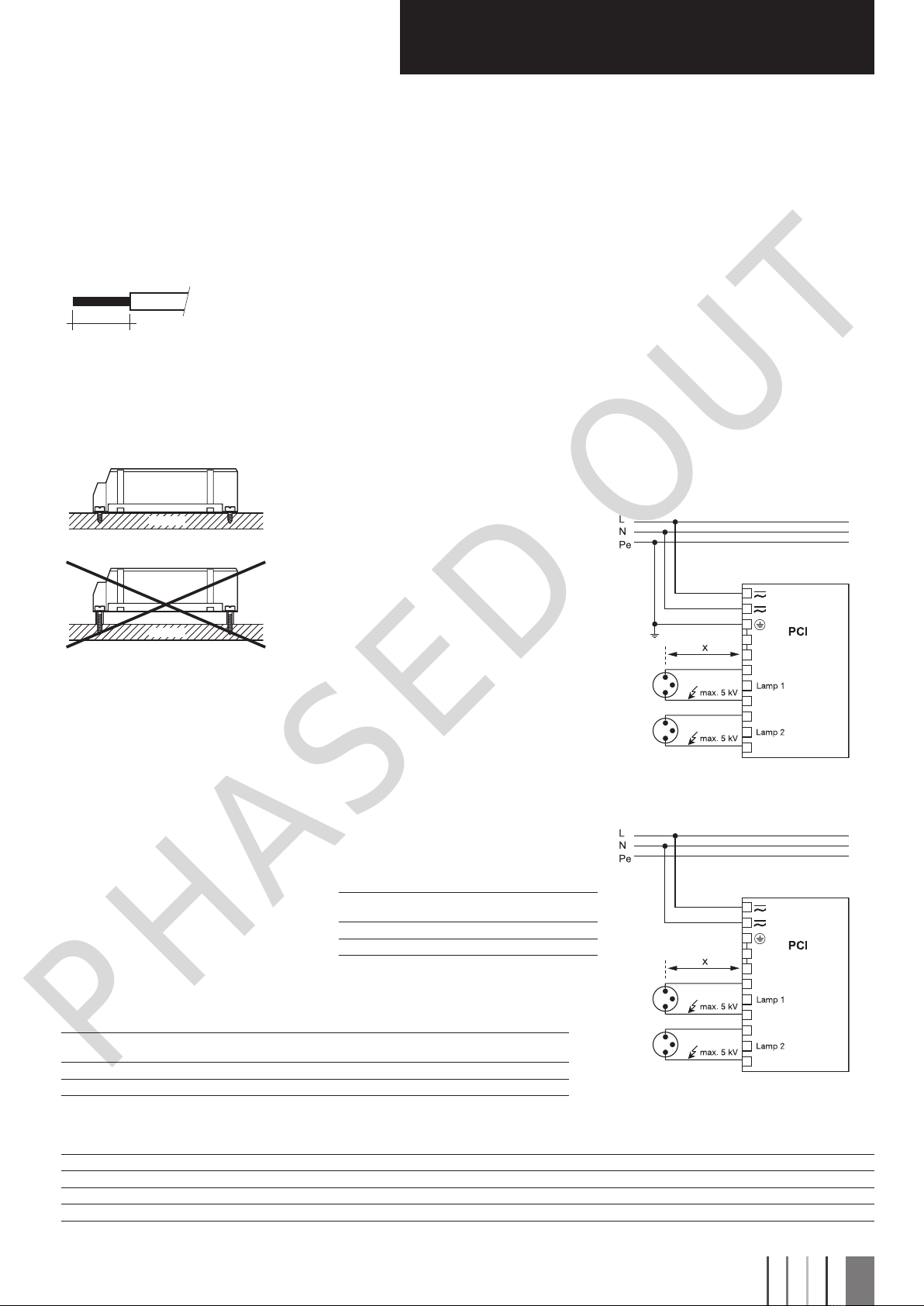
Circuit diagram PCI class 1 application
Standards
EN55015(radiointerference)
EN61000-3-2(mainsharmonics)
EN61347-2-12
EN61547(interferenceimmunity)
CEmark
EMV-VDEmark
ENECmark
Radio interference
•Donotcrossmainsandlampcables.
•Donotlaymainscablestogetherwithlampcables
(ideallytheyshouldbe5–10cmapart).
•Donotleadmainscablestoocloselyalongthe
electronicballast.
•Twistlampcables.
•Increasethedistancebetweenlampcables
andearthedmetalsurfaces.
•Keepthemainscableintheluminaireshort.
•Parallelruns(x)ofmainsandlampcablesmustbe
keptasshortaspossible.
Note on wiring
Thelengthofthelampwiresislimitedbythe
valueofcablecapacitance.Themaximumof
120pFwouldenableconnectionofapproximately
1.5metresoflampwireforeachlamp.
Inclass1luminairesitisnecessarytoearththebal-
lastandtheluminaireviatheearthterminal,
inclass2luminairesnot.
Toavoidthedamageofthecontrolgear,thewiring
mustbeprotectedagainstshortcircuitstoearth
(sharpedgedmetalparts,metalcableclips,louver,
etc.).
Important advise
Whenalampischanged(attheendofitslife),
ifalampismissingorafterovertemperature
shutdownthemainsvoltageoftheECGmust
bedisconnected.
Warning – starting voltage up to max. 5 kV!
Notsuitableforusewithlampswith
integralignitors.
Circuit diagram PCI class 2 application
Installation instructions
Wiring type and cross section
Strandedwirewithendferrulewithacrosssection
of1.5mm2orsolidwireupto2.5mm2maybeused
forwiring.Strip6mmofinsulationfromthecables
toensureperfectoperationofthescrew
terminals.
6mm
0.5–2.5mm²
luminaire
PCI
luminaire
gap
PCI
Mounting recommendation
ToensureoptimumheatremovaltheECGshould
bemountedonametalplate(luminairebody)No
insulatorsbetweentheECGandthethecooling
surface(air,adhesivetape,etc.).Finallyimportant
remainsthetemperaturemeasurement.
Safety switch off
End of life of the lamps
Attheendoftheirusefullife,lampsoftencycleon/
off.ThePCIballastrecognisesthiscondition
andswitchesoffthelamp,afterthreecompleteon/
offcyclesandwhilstthesupplyhasbeen
unswitched.Completelampswitchoffenables
easyidentificationofadefectivelampinthe
application.Afterachangeofthefaultylampand
aninterruptionofthemainssupply(mainsreset)the
ballastwillstrikethelamp.Whenthereisnolampin
circuitoradefectivelampisconnected
totheballast,theballastwillswitchoffafterapr.
25minutes(3.5minutesofignitiontime).
Overtemperature shutdown
TheunitsshutdownatDtapprox.+10°C
comparedwithtc/ta.Amainsresetmustbe
carriedoutsothattheunitsswitchonagain.
Overload strength
320VAC/1h
Ifseveralballastsareinstalledinmasts,boxes,etc.,
measuresmustbetakentoavoidoverheatingof
individualcomponents.
Loading of automatic circuit breakers
Automaticcircuitbreakertype C10 C13 C16 C20 B10 B13 B16 B20
InstallationØ1.5mm21.5mm21.5mm22.5mm21.5mm21.5mm21.5mm22.5mm2
PCI 2/35 14 25 36 42 814 18 18
PCI 2/70 714 20 20 4 6 7 7
Harmonic distortion in the mains supply
Ballast
Type THD 357911
PCI 2/35 7.5 6.0 3.5 3.5 3.5 1.5
PCI 2/70 7.5 4.5 5.0 2.5 2.5 1.0
Ballast lumen factor
EN 60929 8.1
Type
AC/DCBLF
atU=198-254V,25°C
PCI 2/35 1.0
PCI 2/70 1.0


