TRIUMPH BOARD PJ1000 ST DLP User manual

Service manual
PJ1000 ST DLP

Preface
This manual is applied to PJ1000 projection system. The manual gives you a brief
description of basic technical information to help in service and maintain the product.
Your customers will appreciate the quick response time when you immediately
identify problems that occur with our products. We expect your customers will
appreciate the service that you offer them.
This manual is for technicians and people who have an electronic background.
Please send the product back to the distributor for repairing and do not attempt to
do anything that is complex or is not mentioned in the troubleshooting.
Notice: The information found in this manual is subject to change without prior notice.
Any subsequent changes made to the data herein will be incorporated in
future edition.
© TRIUMPH BOARD 2016

Table of Content
Chapter 1 Introduction
Highlight
Compatible Mode 1-1
1-2
Chapter 2 Disassembly Process
Equipment Needed & Product Overview 2-1
Disassemble Filter and Focus Ring 2-2
Disassemble Lamp Module 2-3
Disassemble Top Cover Module 2-4
Disassemble Lamp Cover 2-5
Disassemble Main Board Module and Shielding 2-6
Disassemble Speaker Module and Filter Holder 2-11
Disassemble Engine Module 2-12
Disassemble Blower Module and Thermal Vent 2-16
Disassemble LVPS Module 2-17
Disassemble Bottom Shielding and IO Cover 2-18
Rod Adjustment 2-20
Repair Action 2-21
Chapter 3 Troubleshooting
LED Lighting Message For Projector 3-1
Main Procedure 3-2
No power troubleshooting 3-3
Power troubleshooting 3-4
Image troubleshooting 3-5
© TRIUMPH BOARD 2016

Remote control troubleshooting 3-9
Network troubleshooting 3-10
Audio troubleshooting 3-11
Chapter 4 Test & inspection
Test Equipment Needed 4-1
Test Condition 4-1
Auto Waveform and Fan Calibration 4-2
I/O Port Test 4-3
VGA Port Test 4-3
S-Video and Audio Test 4-8
Video Port Test 4-9
HDMI port Test 4-9
HDTV Test 4-9
Component Port Test 4-10
3D Test 4-10
RJ45 Port Test 4-10
Run In Test 4-14
Test Inspection procedure 4-14
Re-write Lamp Usage Hour 4-16
Chapter 5 Firmware Upgrade
Section 1: System Firmware Upgrade 5-1
Section 2: 8051 Firmware Upgrade Procedure 5-9
Section 3: Network Firmware Upgrade Procedure 5-14
© TRIUMPH BOARD 2016

Chapter 6 EDID Upgrade
EDID Upgrade 6-1
Appendix A
Exploded Image I
Appendix B
Serial Number System Definition I
PCBA Code Definition II
© TRIUMPH BOARD 2016

1. Introduction
1-
© TRIUMPH BOARD 2016
No Item Description
1Dimensions (WxDxH) • 288x219x77mm (WxDxH) (w/o feet)
• 288x219x87mm (WxDxH) (w/ feet)
2 Power Supply • Universal AC 100 – 240 V ,50-60 Hz
3Power Consumption • Bright (Normal): TYP 295W MAX 325W @ 110VAC
• ECO:TYP 245W MAX 270W @ 110VAC
4 Native resolution • Native Resolution: 1024x768(XGA)
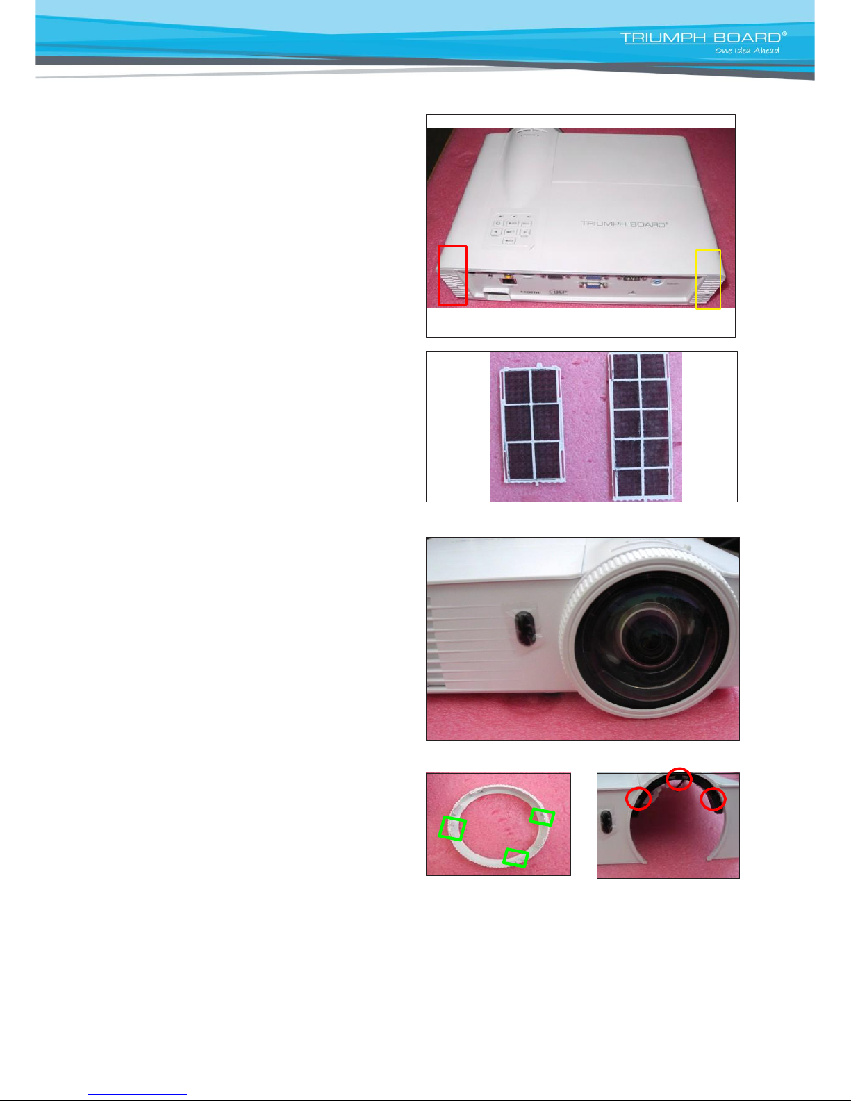
5 Projection lens • YM23LL
6 Throw Ratio • 0.626 (D/W) @ 77
7 Brightness • Typical: 2400 lumens
• Minimum: 2040 lumens
8 Color Wheel • 6 segments (R81Y41G84C31W52B71)
9 DMD chip • TI DMD 0.55” XGA 2xLVDS S450
10 System controller • TI DDP2431
11 Lamp Type • 240 Watt OSRAM E20.8 Lamp
12 Lamp Life
• Bright Mode (Normal Mode)
3500 Hours Standard @ 240W, 50% Survival Rate
• STD Mode (ECO Mode)
5000 Hours Typical @ 190W, 50% Survival Rate
13 Video Compatibility
• NTSC: M/J ,3.58MHz, 4.43 MHz
• PAL: B, D, G, H, I, M, N, 4.43MHz
• SECAM: B, D, G, K, K1, L, 4.25/4.4 MHz
• /05/42(P0801,)zH06/05(P/i0801,)zH06/05(p027:VTDH
60Hz)
• SDTV:480i/p, 576i/p
14 Altitude&Temperature
• Non-operation: Sea Level to 40,000 feet
Operating: Sea Level to 10,000 feet (@23°C);
&teef0005@edomedutitlahgihothctiwslaunam
above
• Operating: 0 to 10,000 feet (5 to 40ºC)
Operating Testing:5°C~40°C @ 0~2,500 feet
5°C~35°C @ 2,500~5,000 feet
5°C~30°C @ 5,000~10,000 feet
15 Input signal spec
• VGA-in x2
• Composite Video x1
• HDMI v1.3
• S-Video (Mini DIN) x 1
• Audio input (Mini Jack) x 1
•
RS232 control (9 pin)
•
USB type B(remote mouse simulation)
• RJ45
© TRIUMPH BOARD 2016

© TRIUMPH BOARD 2016
SVGA 800x600 75 46.90
SVGA 800x600 72 48.10
SVGA
800x600
80
-
SVGA 800x600 85 53.70
832x624 72 -
832x624
75
-
XGA
1024x576 50 -
XGA
1024x576 60 -
XGA
1024x768
60
48.40
XGA
1024x768 70 56.50
XGA
1024x768 72 57.70
XGA
1024x768
75
60
XGA
1024x768
85
68.70
1152x864 60 -
1152x864 70 -
1152x864
75
-
1152x864 85 -
1152x870 75 -
PC Signal
ModeResolution V-Sync[Hz] H-Sync(KHz)
VGA
640x350 70 31.50
VGA
640x350 85 37.90
VGA
720x350 70 31.50
VGA
640x400 70 31.50
VGA
640x400 85 37.90
VGA
720x400 70 31.50
VGA
720x400 85 37.90
720x576 50 -
720x576 60 -
VGA 640x480 60 31.50
VGA
640x480 67 -
VGA
640x480 72 37.90
VGA
640x480 75 37.50
VGA
640x480 85 43.30
SVGA 800x600 56 35.20
SVGA 800x600 60 37.90
1-2 Compatible Mode
© TRIUMPH BOARD 2016

ModeResolution V-Sync[Hz] H-Sync(KHz)
HDTV 1280x720 60 45.00
HDTV 1280x720p 50/60 -
SDTV 720x576 50 31.30
SDTV 720x576i 50 -
SDTV 720x576p 50 -
SDTV 720x480 60 31.50
SDTV 720x480i 60 -
SDTV 720x480p 60 -
MAC LC 13” 640x480 34.98 66.66
MAC II 13”640x480 35.00 66.68
MAC 16” 832x624 49.73 74.55
MAC 19” 1024x768 60.24 75
MAC 1152x870 68.68 75.06
MAC G4 640x480 31.35 60
i MAC DV 1024x768 60 75
i MAC DV 1152x870 68.49 75
Note: If the compatibility supportive signal is different from user's manual,
please refer to user's manual.
© TRIUMPH BOARD 2016
WXGA
1280x768
75
-
WXGA 1280x768 85 -
WXGA-800 1280x800 60 -
SXGA
1280x1024
60
64.00
SXGA 1280x1024 75 80.00
SXGA 1280x1024 85 91.10
SXGA+ 1400x1050 60 -
UXGA
1600x1200
60
75.00
HDTV 1920x1080 30 33.80
HDTV 1920x1080 25 28.10
HDTV
1920x1080i
50/60
-
HDTV 1920x1080p 24/25/30/50/60 -
HD720
1280x720
50
-
HD720 1280x720 60
HD720 1280x720 75
HD720
1280x720
85
WXGA 1280x768 60 47.40
WXGA 1280x768 70 -
© TRIUMPH BOARD 2016

2. Disassembly Process
2-1 Equipment Needed & Product Overview
1. Screw Bit (+): 105
2. Screw Bit (+): 107
3. Screw Bit (-): 107
4. Hex Sleeves 5mm
5. Long Nose Nipper
6. Tweezers
7. Projector
* Before you start: This process is protective level II. Operators should wear electrostatic chains.
© TRIUMPH BOARD 2016

2-2 Disassemble Filter and
Focus Ring
1. Pull down the tendon (as red square) to
disassemble the left filter.
2. Pull down the tendon (as yellow square)
to disassemble the right filter.
3. Disassemble the left filter and the
right filter.
left filter right filter
4. Please rotate the focus ring outward so
as to take out the focus ring easily.
5. Pull out the focus ring.
Note: - When you assemble the focus
ring, ensure the card slot (as
green square) placed in the right
area properly (as red circle), and
the focus ring can be well adjusted.
Focus Ring
© TRIUMPH BOARD 2016

2-3 Disassemble Lamp
Module
1. Loosen 1 screw (as red circle) on the
lamp cover.
2. Loosen 2 screws (as yellow circle) on the
lamp module.
3. Take off the lamp module.
lamp module
© TRIUMPH BOARD 2016

2-4 Disassemble Top Cover
Module
1. Unscrew 2 screws (as red circle) from the
top cover.
2. Unscrew 8 screws (as green circle) from
the bottom cover.
3. Press two sides of the projector as the
blue arrows point.
© TRIUMPH BOARD 2016

4. Unplug 1 connector (as blue square),then
remove the top cover module.
5. Disassemble the top cover module.
2-5 Disassemble Lamp
Cover
1. Unscrew 2 screws (as red circle) and
tear off the tape (as yellow square) to
disassemble the IR sensor module.
2. Unscrew 4 screws (as blue circle) to
disassemble the zoom ring.
Zoom Ring IR Sensor Module
© TRIUMPH BOARD 2016

3. Then remove the lamp cover from the top
cover.
Lamp Cover
2-6 Disassemble Main Board
Module and Shielding
1. Tear off the tape (as blue square) and
unscrew 4 screws (as red circle).
© TRIUMPH BOARD 2016

2. Unscrew 8 hex screws (as green
circle) and 1 screw (as yellow circle).
3. Unplug 6 connectors (as red square).
4. Unplug 1 connector (as green square) of
color wheel.
A B C D E F
© TRIUMPH BOARD 2016

Note: - Make sure cables plug into the correct
ports when assembling the unit.
Please refer to the below table details of
each connector on main board.
Item
Male Connector
on Main Board
The key feature
Figure
A
Speaker
Compose of Yellow/
White Wire and Black
tube(2 pin)
B
Front IR
Compose of Black/
Yellow/Pink Wire and
Black tube(3 pin)
C
Photo Sensor BD
Compose of Black/
White/Red Wire, Red
Connector and Black
tube(3 pin)
D
Fan
Compose of Black/
White/Red Wire,
White Connector (3
pin)
E
Blower
Compose of Black/
Blue/Pink Wire, White
Connector (3 pin)
F
Lamp driver
Black wire tube (5
pin)
© TRIUMPH BOARD 2016

5.Unplug 1 connector (as yellow square).
6. Disassemble main board module.
7. Unscrew 2 screws (as green circle).
8. Unscrew 1 screw (as blue circle) to
separate LAN board and daughter board.
Daughter Board LAN Board
© TRIUMPH BOARD 2016

9. Unscrew 3 hex screws (as red circle) to
disassemble the LAN board.
10. Unscrew 3 screws (as green circle) to
disassemble the shielding.
© TRIUMPH BOARD 2016

2-7 Disassemble Speaker
Module and Filter Holder
1. Unscrew 1 screw (as yellow circle) to
disassemble the speaker module.
2. Separate the speaker and rubber.
Rubber Speaker
3. Separate the filter holder (as yellow
square).
Left Filter Hold Right Filter Hold
© TRIUMPH BOARD 2016

2-8 Disassemble Engine
Module
1. Unscrew 4 screws (as yellow circle) to
disassemble the engine module.
2. Unscrew 2 screws (as red circle) to
disassemble the color wheel module.
© TRIUMPH BOARD 2016
Other manuals for PJ1000 ST DLP
1
Table of contents
Other TRIUMPH BOARD Projector manuals