TRM SR-ACC-SPL Service manual

Product
Certifications:
TRM SR-ACC-SPL/TEE
Self Regulating Cable Splice and Tee Kit
Installation Instruction Manual
Thermal Resources Management (TRM)
175 Idema Road, Markham,
ON, Canada, L3R 1A9
Tel: 1-905-940-4737
Fax: 1-905-940-4731
www.TRMheatingcables.com
Item Quantity Description
A 1 Clamp Tie
B 1 Black Cloth Tape (6” long)
C 1 Heat Shrink Tubing (8” x 1”)
D 3 Cable Ties
E 5 Mastic Strips (1 ½” x ½”)
F 3 Heat Shrink Tubing (1” x ½”)
G 6 Heat Shrink Tubing (1” x 1/8”)
H 2 Heat Shrink Cap
I 2 Insulated Bus Wire Crimps
J 1 Heat Shrink For Ground (1” x ½”)
K 1 Uninsulated Braid Crimp
Kit Contents:
WARNING:
Electric Shock Hazard. You MUST disconnect all power before installing or servicing
heating cable and accessories. A qualified electrician must perform installation and
servicing of heating cables and accessories. Heating cables must be grounded in
accordance with the National Electrical Code. Failure to comply with this code can
result in personal injury or property damage.
Product
Certifications:
Thermal Resources Management (TRM)
175 Idema Road, Markham,
ON, Canada, L3R 1A9
Tel: 1-905-940-4737
Fax: 1-905-940-4731
www.TRMheatingcables.com
Important notes:
1) All electrical wiring including GFCI (ground fault circuit interrupters) must be installed
in compliance with the National and Local Electrical Codes by qualified person(s)
2) Article 426 of ANSI/NFPA 70 of the National Electrical Code (NEC Section 62 of
CAN/CSA-C22.1, Canadian Electrical Code, Part 1 (CEC)) Governs the installation of
these heat tracing systems
3) TRM SR-ACC-SPL/TEE (Splice and Tee Kit) is suitable for use with TRMSR heating
Cables
4) Cables should be terminated into certified junction boxes that are appropriate for the
cable termination location
5) Use 30-mA ground fault protection on each heating cable circuit for maximum
protection
6) The black heating cable core is conductive and can short. It must be properly insulated
and kept dry
7) Keep ends of heating devices and kit components dry before and during installation
work
8) The conductive layer of this heating device must have a suitable grounding/earthing
terminal
9) Do not break braid or bus wire strands when scoring the jacket or conductive core.
Damaged bus wires can overheat or short out
10) Keep bus wires separated. Bus wires will short if they touch each other
11) Replace damaged components. Components damaged by heat can short.
12) Utilize a heat gun with a low heat flame, do not use a torch with a blue flame as that
would melt/compromise the heat shrink tubing. Charring or burning the heat shrink
tubing can produce fumes that may cause irritation to skin,, eyes, nose, and throat
13) Do not heat up components of this kit (except for the heat shrink tubes)
14) When installing this cable, only use fire-resistant insulation materials such as fiberglass
wrap
15) Do not twist the cable during installation
Assembly Tools Required:
Utility knife, scissors, side cutters, needle-nose pliers, linesman pliers, channel lock
pliers, crimping tool, flathead screwdriver, heat gun, measuring tape/ruler.
TRM SR-ACC-SPL/TEE
Self Regulating Cable Splice and Tee Kit
Installation Instruction Manual
Product
Certifications:
Thermal Resources Management (TRM)
175 Idema Road, Markham,
ON, Canada, L3R 1A9
Tel: 1-905-940-4737
Fax: 1-905-940-4731
www.TRMheatingcables.com
•The multiplier for power output (w/ft) for 5W TRM BR type cables for 208VAC operation is .85
•The multiplier for power output (w/ft) for 8W TRM BR type cables for 208VAC operation is .89
•The heating circuit lengths calculations would also change for 208VAC operation, the multiplier for AL type cables would
be 0.93, and the multiplier for BR type cables would be .92
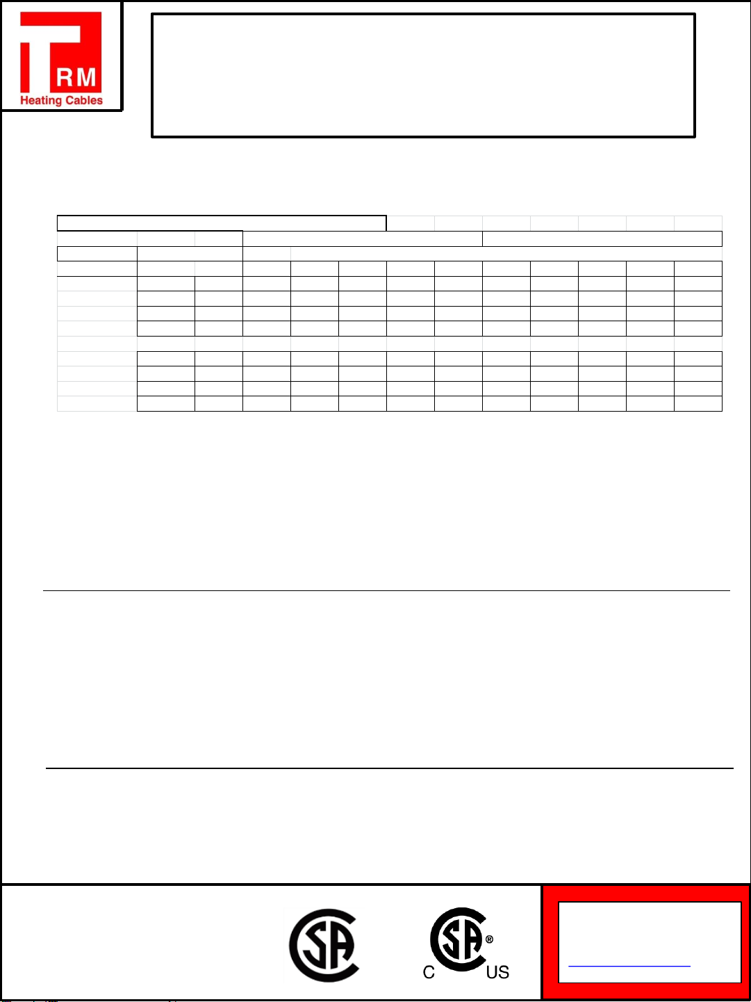
Cable Selection
F C 15A 20A 30A 40A 15A 20A 30A 40A
TRM BR SR 50 10 225 265 265 265 450 530 530 530
5W 32 0225 265 265 265 450 530 530 530
14 -10 180 235 265 265 360 470 530 530
-22 -30 125 165 245 265 245 325 490 530
TRM BR SR 50 10 150 200 210 210 300 400 420 420
8W 32 0125 175 210 210 250 350 420 420
14 -10 110 150 210 210 220 300 420 420
-22 -30 85 115 175 210 170 230 350 420
240V
120V
Maximum Circuit Lengths
Start-Up Temperature
Breaker Sizes
Controls and GFI:
TRM SR can function safely without the use of controls, but it is strongly recommended to utilize thermostats or controllers
to maximize the efficiency of the cables while simultaneously minimizing electrical costs.
For further information or for design assistance with controls and/or sensors that work in concert with our SR cable, please
call TRM directly
Circuit protection depends on the breaker size being used and the start-up temperature. NEC 1999 requires the use of
ground fault protection breakers for heating cable. The above chart shows the maximum circuit length for a given breaker
rating. To determine the number of circuits required for each pipe, divide the total cable (circuit) length by the maximum
circuit length found in the chart. Round up to the next higher number.
TRM SR-ACC-SPL/TEE
Self Regulating Cable Splice and Tee Kit
Installation Instruction Manual

Product
Certifications:
Thermal Resources Management (TRM)
175 Idema Road, Markham,
ON, Canada, L3R 1A9
Tel: 1-905-940-4737
Fax: 1-905-940-4731
www.TRMheatingcables.com
B
SR Cable Construction
Standard
A. Buss Wires
Twin 16 AWG copper buss
wires provide good current
capability
B. Matrix
A semi-conductive polymer
core whose electrical
resistance varies with
temperature. When process
temperature drops, the core’s
heat output increases;
conversely, as process
temperature rises, heat
output decreases
A B C D
C. Tinned Copper Braid
The braid covering the jacket
provides an effective ground
path and mechanical
Protection
D. Jacket
The flame retardant insulation
jacket is a polyolefin material with
excellent water resistance. It also resists
certain mildly corrosive Chemicals
Description
Thermal Resources Management brand SR
cable is ideal for keeping metal and plastic
pipes warm in commercial construction,
institutional buildings and some industrial freeze
protection applications. TRM SR cable is
constructed of a self-regulating polymer core
that varies its output along its entire length,
saving energy and eliminating hot spots along
the pipe. Parallel construction makes it easier to
install than zone or series types of cable since it
can be cut to length at any point on the pipe. It
can be single overlapped without overheating
the cable.
Approvals
Certified for ordinary areas
Applications
Commercial
Construction
•Cooling Towers
•Chilled Water and Plumbing
Pipes
•Sump Discharge Pipes
•Wet Sprinkler System
•Exposed P-traps
•Roof and Gutter Deicing
•Heat Loss Replacement
Industrial
•Water Treatment Facilities
•Vessel Freeze Protection
•Safety Shower Lines
TRM SR-ACC-SPL/TEE
Self Regulating Cable Splice and Tee Kit
Installation Instruction Manual
Product
Certifications:
Thermal Resources Management (TRM)
175 Idema Road, Markham,
ON, Canada, L3R 1A9
Tel: 1-905-940-4737
Fax: 1-905-940-4731
www.TRMheatingcables.com
TRM SR-ACC-SPL/TEE
Self Regulating Cable Splice and Tee Kit
Installation Instruction Manual
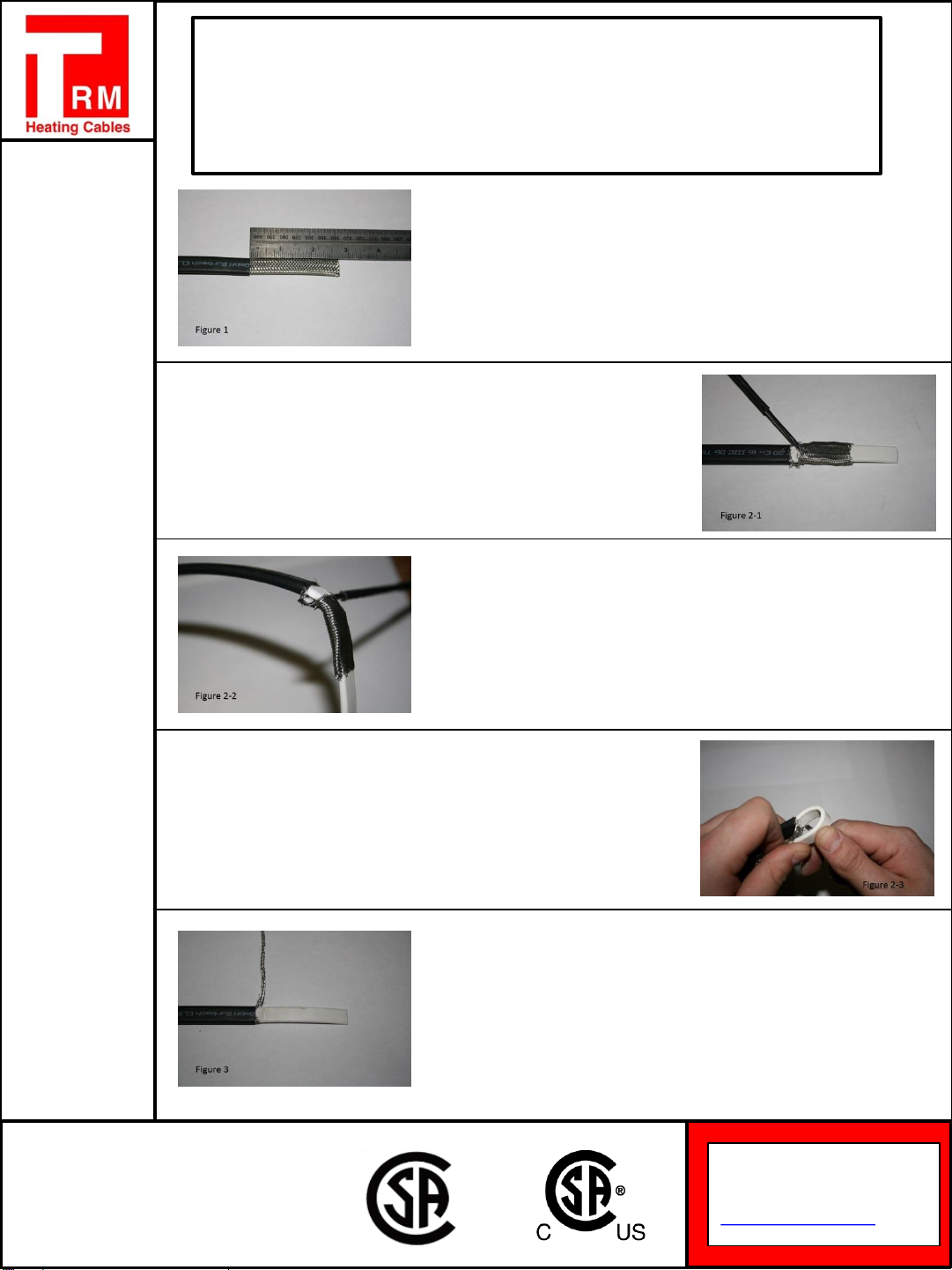
1.) Figure 1: Slice completely around the black outer
jacket 2 ¾” from the cables end, being careful not to cut
braid or inner jacket. Then, bend the cable where sliced to
break jacket, and peel off.
2.) Figure 2-1: Carefully push braid back (away from the
end of cable) to loosen and spread apart as shown
2.) Figure 2-2: Bend the cable and push the braid until
there is enough room between the bottom of the cable
and the braid to fit a screwdriver
2.) Figure 2-3: Bend the cable over and hold in left hand
while keeping it pinned between your screwdriver and
your right thumb as shown. Slowly pull the cable back and
out of the braid. The heating cable must be bent as
shown, so it can be pulled through the braid opening
3.) Figure 3: Twist together braid and put off to one side
as shown.
Product
Certifications:
Thermal Resources Management (TRM)
175 Idema Road, Markham,
ON, Canada, L3R 1A9
Tel: 1-905-940-4737
Fax: 1-905-940-4731
www.TRMheatingcables.com
TRM SR-ACC-SPL/TEE
Self Regulating Cable Splice and Tee Kit
Installation Instruction Manual
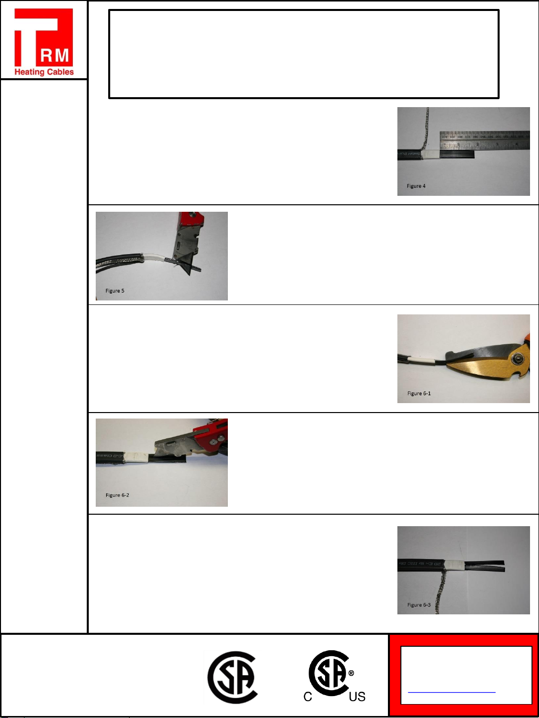
4.) Figure 4: Score the inner jacket of cable 1 ¾” from the
cable’s end. Bend cable to break jacket at score, then
peel off
5.) Figure 5: Shave off the outer matrix material from
conductor with a utility knife. Repeat on opposite side of
cable for the second conductor
6.) Using either a pair of scissors (Figure 6-1) or a utility
knife (Figure 6-2) make a cut through the centre matrix
material 1 ¾”, down to where the inner jacket begins
(Figure 6-3).
6.) Using either a pair of scissors (Figure 6-1) or a utility
knife (Figure 6-2) make a cut through the centre matrix
material 1 ¾”, down to where the inner jacket begins
(Figure 6-3).
6.) Using either a pair of scissors (Figure 6-1) or a utility
knife (Figure 6-2) make a cut through the centre matrix
material 1 ¾”, down to where the inner jacket begins
(Figure 6-3).

Product
Certifications:
Thermal Resources Management (TRM)
175 Idema Road, Markham,
ON, Canada, L3R 1A9
Tel: 1-905-940-4737
Fax: 1-905-940-4731
www.TRMheatingcables.com
TRM SR-ACC-SPL/TEE
Self Regulating Cable Splice and Tee Kit
Installation Instruction Manual
7.) Figure 7-1: using a utility knife, cut the matrix material
around the base of each conductor. Be careful not to cut
the conductor
7.) Figure 7-2: Once cut is done from 7-1, carefully peel
off the matrix material from the conductors
8.) Figure 8-1: Slip black heat shrink tubes (G) onto
conductors up to the inner jacket
8.) Figure 8-2: Shrink tubing by moving heat source side
to side continuously. Be careful not to leave the heat
source on one area for very long
9.) Figure 9-1: Centre the black heat shrink (F) over the
end of cable as shown

Product
Certifications:
Thermal Resources Management (TRM)
175 Idema Road, Markham,
ON, Canada, L3R 1A9
Tel: 1-905-940-4737
Fax: 1-905-940-4731
www.TRMheatingcables.com
TRM SR-ACC-SPL/TEE
Self Regulating Cable Splice and Tee Kit
Installation Instruction Manual
9.) Figure 9-2: Heat the tube evenly until it shrinks and
adhesive flows out of both ends.
9.) Figure 9-3: While tubing is still hot; pinch the end of
the tube between the two conductors with needle nose
pliers, and hold for 10 seconds to ensure seal.
9.) Figure 9-4: Repeat steps 1 through 9 for remaining
two cables.
10.) Figure 10-1/10-2: Remove paper from mastic strip
(E). Wrap a piece of mastic around the outer jacket on
each heating cable, 2” down from the end of the outer
jacket. (If needed, each mastic strip can be stretched to
accommodate thicker types of heating cable)
10.) Figure 10-1/10-2: Remove paper from mastic strip
(E). Wrap a piece of mastic around the outer jacket on
each heating cable, 2” down from the end of the outer
jacket. (If needed, each mastic strip can be stretched to
accommodate thicker types of heating cable)

Product
Certifications:
Thermal Resources Management (TRM)
175 Idema Road, Markham,
ON, Canada, L3R 1A9
Tel: 1-905-940-4737
Fax: 1-905-940-4731
www.TRMheatingcables.com
TRM SR-ACC-SPL/TEE
Self Regulating Cable Splice and Tee Kit
Installation Instruction Manual
11.) Figure 11-1: Carefully align each heating cable on
top of one another, pressing mastic strips together.
Fasten with a cable tie (D) at 7 ¾” and 10 ¾” from the end
of the cable as shown.
11.) Figure 11-2: Twist together each of the cables
ground braids
11.) Figure 11-3: Slide uninsulated crimp (K) over braid to
within ½” of heating cable.
11.) Figure 11-4: Crimp braid as shown, at least twice,
using a crimping tool.
12.) Figure 12-1: Cut off the excess braid.

Product
Certifications:
Thermal Resources Management (TRM)
175 Idema Road, Markham,
ON, Canada, L3R 1A9
Tel: 1-905-940-4737
Fax: 1-905-940-4731
www.TRMheatingcables.com
TRM SR-ACC-SPL/TEE
Self Regulating Cable Splice and Tee Kit
Installation Instruction Manual
12.) Figure 12-2: Position the braid crimp connector as
shown. Ensure crimp connector lays flat.
13.) Figure 13-1: Slide the black heat shrink tube (J) over
uninsulated braid crimp (K).
13.) Figure 13-2: Heat tube evenly until it shrinks and
adhesive flows out of both ends.
13.) Figure 13-3/13-4: Immediately after shrinking, pinch
the end of the tube with a pair of pliers and hold until the
end stays sealed
13.) Figure 13-3/13-4: Immediately after shrinking, pinch
the end of the tube with a pair of pliers and hold until the
end stays sealed
Product
Certifications:
Thermal Resources Management (TRM)
175 Idema Road, Markham,
ON, Canada, L3R 1A9
Tel: 1-905-940-4737
Fax: 1-905-940-4731
www.TRMheatingcables.com
TRM SR-ACC-SPL/TEE
Self Regulating Cable Splice and Tee Kit
Installation Instruction Manual
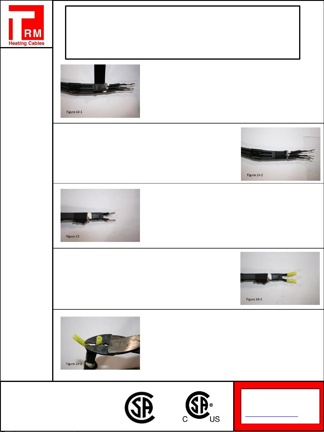
14.) Figure 14-1/14-2: Fold the crimped braid back on top
of the heating cables. Then wrap the black cloth tape (B),
around the crimp and heating cables. Ensure to cover the
crimp completely.
14.) Figure 14-1/14-2: Fold the crimped braid back on top
of the heating cables. Then wrap the black cloth tape (B),
around the crimp and heating cables. Ensure to cover the
crimp completely.
15.) Figure 15: Take one conductor from the same side
of each cable and twist the wires together as shown. Be
careful not to twist together conductors from the same
cable.
16.) Figure 16-1: Slide insulated bus wire crimps (I) over
each conductor
16.) Figure 16-2: Using a crimping tool, crimp each set of
conductors together

Product
Certifications:
Thermal Resources Management (TRM)
175 Idema Road, Markham,
ON, Canada, L3R 1A9
Tel: 1-905-940-4737
Fax: 1-905-940-4731
www.TRMheatingcables.com
TRM SR-ACC-SPL/TEE
Self Regulating Cable Splice and Tee Kit
Installation Instruction Manual
17.) Figure 17-1: Slide heat shrink cap (H) over each set
of bus wire crimps.
17.) Figure 17-2/17-3: Apply heat from the end of the cap
evenly until it shrinks and adhesive flows out. If adhesive
does not appear, additional heat is needed.
17.) Figure 17-2/17-3: Apply heat from the end of the cap
evenly until it shrinks and adhesive flows out. If adhesive
does not appear, additional heat is needed.
18.) Figure 18-1: If the adhesive seals from the heat
shrink tubes (F) melt while shrinking cap, pinch again with
needle nose pliers as shown.
18.) Figure 18-2: Ensure the heat shrink tube is
completely sealed between the two conductors and that
there are no visible gaps.

Product
Certifications:
Thermal Resources Management (TRM)
175 Idema Road, Markham,
ON, Canada, L3R 1A9
Tel: 1-905-940-4737
Fax: 1-905-940-4731
www.TRMheatingcables.com
TRM SR-ACC-SPL/TEE
Self Regulating Cable Splice and Tee Kit
Installation Instruction Manual
19.) Figure 19-1: Remove release paper from mastic strip
(E) and stretch the width (1” side) of the mastic strip as
shown. (Stretching the strips is necessary because the
width cannot fully wrap around each of the heat shrink
caps).
19.) Figure 19-2/19-3: Wrap a stretched mastic strip
around each of the heat shrink caps as shown. Press
mastic strip into itself to ensure a good grip
19.) Figure 19-2/19-3: Wrap a stretched mastic strip
around each of the heat shrink caps as shown. Press
mastic strip into itself to ensure a good grip
20.) Figure 20: Squeeze the mastic strips together and
hold for 5 seconds.
21.) Figure 21-1: Slide the heat shrink tube (C) over
cables. Place the edge of heat shrink ½” past the edge of
the mastic strips on each cable.

Product
Certifications:
Thermal Resources Management (TRM)
175 Idema Road, Markham,
ON, Canada, L3R 1A9
Tel: 1-905-940-4737
Fax: 1-905-940-4731
www.TRMheatingcables.com
TRM SR-ACC-SPL/TEE
Self Regulating Cable Splice and Tee Kit
Installation Instruction Manual
21.) Figure 21-2: Starting at the point shown, apply heat
to tube while working your way toward the end of the
cable
21.) Figure 21-3: When heating, work the heat gun side
to side to ensure an even distribution of heat along the
tube.
21.) Figure 21-4: Shrink the start of the tube completely,
until adhesive appears at the bottom and you can see the
shape of the mastic strips underneath. Continue to heat
the tube completely. Make sure to keep heating after the
tube has shrunk, to melt the adhesive and the mastic
strips inside the tube.
22.) Figure 22-1: Immediately after shrinking, pinch the
end of the tube with pliers until the end seals.
22.) Figure 22-2/22-3: If the width of the pliers isn’t wide
enough to pinch the entire tube, pinch a second time at
the end of the cable.

Product
Certifications:
Thermal Resources Management (TRM)
175 Idema Road, Markham,
ON, Canada, L3R 1A9
Tel: 1-905-940-4737
Fax: 1-905-940-4731
www.TRMheatingcables.com
TRM SR-ACC-SPL/TEE
Self Regulating Cable Splice and Tee Kit
Installation Instruction Manual
22.) Figure 22-2/22-3: If the width of the pliers isn’t wide
enough to pinch the entire tube, pinch a second time at
the end of the cable.
22.) Figure 22-4/22-5: Ensure the end of the heat shrink
is completely sealed with adhesive.
22.) Figure 22-4/22-5: Ensure the end of the heat shrink
is completely sealed with adhesive.
23.) Figure 23: After the heat shrink has cooled, fold over
the connection end and fasten it with the third cable tie.
Refer to applicable application instruction manual(s)
for installation and testing instructions and
guidelines
This manual suits for next models
1
Table of contents


