Werner A330000 User manual

with certication of a qualied person, or 5,000 pounds (22.2 kN)
without certication.
2. SUBSTRATE: D-Ring Anchorage Connectors must only be used on
steel with a minimum thickness of ¼inch (6.4 mm).
3. FASTENERS: Only use Grade 5 or stronger ⅝inch - 11 steel hex
head bolts and nuts (sold separately).
4. LOADING: D-Ring Anchorage Connectors are permitted to be loaded
in all directions.
5. CONNECTION: Only one travel restraint, work positioning, fall arrest,
or rescue system may be attached to an individual connect point.
6. EXTREME TEMPERATURE: D-Ring Anchorage Connectors are
designed to be used in temperatures ranging from -40°F to +130°F
(-40°C to +54°C). Protection should be provided when used near
welding, metal cutting or similar activities. Contact WernerCo with any
questions concerning high temperature environments.
7. CONTAMINATION: Remove any surface contamination
such as concrete, stucco, roong material, etc., that could
accelerate cutting or abrasion of attached components.
8. ELECTRICAL HAZARDS: Use extreme caution when working near
high voltage power lines due to the possibility of electric current
owing through the D-Ring Anchorage Connector or connecting
components.
9. HEALTH: Minors, pregnant women and anyone with a history of either
back or neck problems should not use this equipment.
10. RESCUE: In the event of a fall over the edge, special rescue
measures may be required.
11. TRAINING: Do not use D-Ring Anchorage Connectors without proper
training from a “competent person” as dened by OSHA 29 CFR
1910.140(b) and 1926.32(f).
12. REPAIRS: Only WernerCo, or persons or entities authorized in writing
by WernerCo, may make repairs or alterations to the equipment.
COMPATIBILITY LIMITATIONS
All connecting subsystems must only be coupled to compatible connectors.
OSHA 29 CFR 1910.140 and 1926.502 prohibit snap hooks from being
engaged to certain objects unless two requirements are met: snap
hook must be a locking type and must be “designed for” making such a
connection. Under OSHA “designed for” means that the manufacturer of
the snap hook specically designed the snap hook to be used to connect
to the equipment in question.
The following connections must be avoided because they can result in
rollout* when a non-locking snap hook is used:
• Direct connection of a snap hook to horizontal lifeline.
• Two (or more) snap hooks connected to one D-ring.
• Two snap hooks connected to each other.
• A snap hook connected back on its integral lanyard.
• A snap hook connected to a webbing loop or webbing lanyard.
• Improper dimensions of the D-ring, rebar, or other connection point in
relation to the snap hook dimensions that would allow the snap hook
keeper to be depressed by a turning motion of the snap hook.
*Rollout: A process by which a snap hook or carabiner unintentionally
disengages from another connector or object to which it is coupled.
D-Ring Anchorage Connector
User Instruction Manual
A330000
WARNING: Compliant fall protection equipment must
only be used as it was designed. Users MUST read and understand
all user instructions provided with the product. Before using a
fall arrest system, users must be trained in the safe use of the
system, as required by OSHA 29 CFR 1910.30 and 1926.503, or local
safety regulations. Misuse or failure to heed these warnings and
instructions may result in injury or even death.
WORK SAFE! WORK SMART!
IMPORTANT
Before use, the user must read and understand these User Instructions.
Keep these User Instructions for reference.
PURPOSE
WernerCo D-Ring Anchorage Connectors are designed to function as an
interface between the anchorage and travel restraint, work positioning, fall
arrest, or rescue system.
USE INSTRUCTIONS
1. Failure to follow all instructions and limitations on the use of the
D-Ring Anchorage Connector may result in serious personal injury or
death.
2. Before using a personal fall arrest system, employees must be trained
in accordance with the requirements of OSHA 29 CFR 1910.30 and
1926.503 in the safe use of the system and its components.
3. Personal fall arrest and rescue systems, including the D-Ring
Anchorage Connector, must be inspected prior to each use for
wear, damage, and other deterioration. Defective components
must be immediately removed from service in accordance with the
requirements of OSHA 29 CFR 1910.140 and 1926.502.
4. The complete fall arrest system must be planned (including all
components, calculating fall clearance, and swing fall) before using.
5. Users must have a rescue plan, and the means at hand to implement
it, that provides for the prompt rescue of the user in the event of a fall,
or assures that the user is able to rescue themselves. A fall over an
edge may require special rescue measures.
6. Store the D-Ring Anchorage Connector in a cool, dry, clean
environment, out of direct sunlight, when not in use.
7. After a fall occurs on the system, immediately remove from service
until a “competent person” can make the determination for reuse or
disposal.
8. WernerCo will provide design information upon request.
9. Field serviceability testing is not required and is not
recommended to be performed by the user.
USE LIMITATIONS
D-Ring Anchorage Connectors have been tested in compliance with the
requirements of ANSI/ASSE Z359.7. Compliance and testing covers only
the hardware and does not extend to the anchorage and substrate to
which the D-Ring Anchorage Connector is attached.
1. ANCHORAGE: D-Ring Anchorage Connectors must only be used
on structures capable of supporting loads applied in all directions
permitted by the fall arrest system of at least: 3,600 pounds (16.0 kN)
Model No.
Material Length Width Connection Size Hole Diameter Weight MBS Compliance Standards
A330000 Alloy Steel;
Stainless Steel
6 in
(154 mm)
3 ⅛in
(80 mm)
2 ⅜in
(61 mm)
5/8 in
(17 mm)
9.5 oz
(268 g)
5,000 lbs
(22.2 kN)
ANSI Z359.18-2017 Type A
OSHA 1910 & 1926

D-Ring Anchorage Connector
120658-01 ©2019 WernerCo Rev B 04/20
User Instruction Manual
A330000
WernerCo Corporate Headquarters: 555 Pierce Road, Suite 300, Itasca, IL 60143
TEL: 888-523-3370 FAX: (724) 588-0315 www.wernerco.com
INSTALLATION
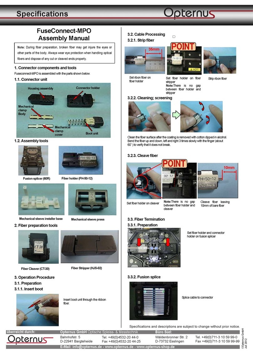
Drill a ⅝inch hole where needed in the anchorage structure. Attach the
D-Ring Anchorage Connector using a ⅝inch - 11 Grade 5 steel hex head
bolt and nut. Torque bolt to 100-150 ft-lbs.
If attaching the D-Ring Anchorage Connector to the support structure
by methods other than instructed, the attachment must be certied by a
qualied person to meet the requirements of the system that will connect to
the D-Ring Anchorage Connector.
INSPECTION
All components of D-Ring Anchorage Connector’s must be inspected
prior to each use and annually by an OSHA dened “competent person”
other than the user. Local, state, governmental and jurisdictional agencies
governing occupational safety may require the user to conduct more
frequent or mandatory inspections.
WARNING: If inspection reveals any defect, inadequate
maintenance, or unsafe condition, remove from service until a
“competent person”, as dened by OSHA 29 CFR 1910.140(b) and
1926.32(f), can determine the need for authorized repair or disposal.
WARNING: Any equipment that has been subjected to the
forces of arresting a fall, or that has a deployed load indicator, must
be removed from service until a “competent person” can determine
the need for authorized repair or disposal.
All D-Ring Anchorage Connectors must be free of corrosion, chemical
attack, alteration, excessive heating or wear.
All markings must be legible and attached to the product.
WARNING: Only WernerCo, or persons or entities authorized
in writing by WernerCo, may make repairs or alterations to the
equipment.
CLEANING AND MAINTENANCE
D-Bolt Anchorage Connectors may be wiped down to remove grease or
dirt with a clean dry cloth.
6 inch
(154 mm)
2 ⅜in
(61 mm)
3 ⅛inch
(80 mm)
⅝inch
(18 mm)
⅝inch
(17 mm)
93 Werner Road, Greenville, PA 16125
888-523-3371
Model: A330000
© 2019 WernerCo
P/N 120674-01 Rev A 9/19
WARNING:
User must follow manufacturer’s
instructions included with the
equipment at the time of shipment
from the manufacturer.
Refer to the instruction manual for
proper installation and stability and
compatibility limitations.
Inspect prior to use.
ADVERTENCIA:
El usuario debe seguir las
instrucciones del manufacturero
incluidas con el equipo al tiempo de
embarque del productor.
Refiera al manual de la instrucción
para las limitaciones apropiadas de la
instalación y de la estabilidad y de la
compatibilidad.
Inspeccione antes de usar.
Standards/Estándares
ANSI Z359.18-2017
Type A OSHA 1910, 1926
Material: Steel/Stainless Steel
Materiales: Acero
Minimum Breaking Strength (MBS): 5,000 lbs
Resistencia Mínima a la rotura: (22.2kN)
Year of manufacture: [YYYY]
Año de la fabricación:
[Serial number]
Inspection Log/Registro de Inspección
1
Year 1
2 3 4 5 6 7 8 9 10 11 12
Year 2
Year 3
Year 4
Year 5
Popular Cables And Connectors manuals by other brands

Cypress
Cypress CLUX-12S Operation manual
Siemens
Siemens 3VL9000-8AQ10 operating instructions

Gleason Reel
Gleason Reel Direct Drive Hazardous Duty Electric Cable Reels... Installation and maintenance instructions
CONCORD
CONCORD CS4WH20B4KDS-A manual

Burndy
Burndy Continental Industries thermOweld CB-15 instructions
E1DT
E1DT E1DT-ASSY-0058 Installation and operation
