tron FX-4132R Configuration guide

FX-4132R CATV AMPLIFIER
User Manuel
www.tron.com.tr 1
Page
Technical Specicaons 2-3
Safety Instrucons 4
Installaon Guidelines 5-6
Slope Gain Control 7-8
Contact 9
CATV Amplier
1218 MHz | DOCSIS 3.1

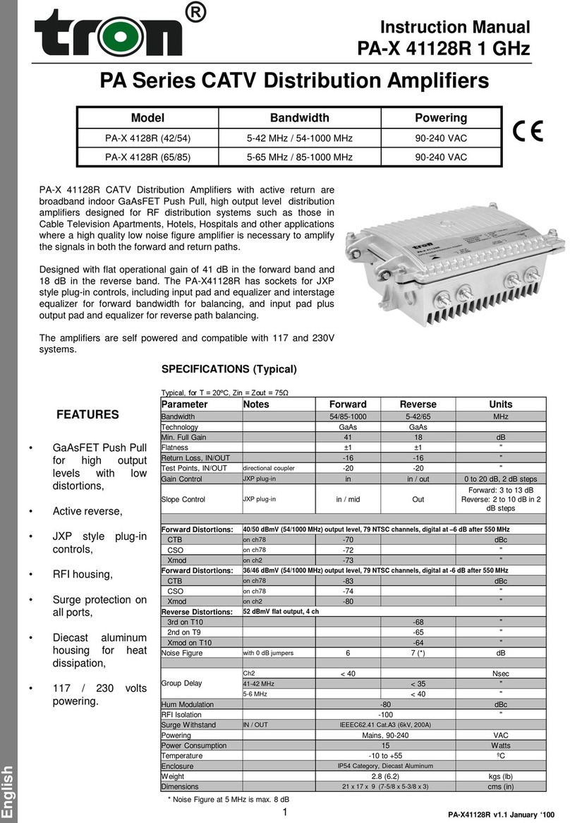
FX4132R Series type amplifiers with active return are broadband indoor GaAs E-pHEMT Push Pull
distribution amplifiers designed for 1.2 GHz DOCSIS 3.1 supported RF distribution systems such as
those in Cable Television Apartments, Hotels, Hospitals and other applications where a high quality low
noise figure amplifier is necessary to amplify the signals in both the forward and return paths.
Universal JXP style pads applicable for both attenuator and equalizer functions.
www.tron.com.tr 2
FX-4132R_R1_181119
FX-4132R
RF Parameters
Forward (Down-Stream)
Technology GaAs E-pHEMT MMIC
Forward Bandwidth 110-1218 MHz
Gain min. 32 dB
Flatness +/-1 dB
Slope Control 0…20 dB JXP plug-in
Gain Control 0…20 dB JXP plug-in
Gain Control (Mid-stage) 0…20 dB JXP plug-in
Slope Control (Mid-stage) 0…20 dB JXP plug-in
RF Test Points in / out –20dB (two-ways)
Output Level
CTB ≥ 60 dBc, CSO ≥ 60 dBc, XMOD ≥ 60 dBc
(EN50083-3: CENELEC 42 channels 99/107 dBuV (8dB Eq)
MER >40dB ,Post BER 10-9(Full Digital Load 254MHz-
1218MHz QAM 256) 95/103dBuV(8dB Eq)
Noise < 7 dB
Return Loss EN 50083/3-Table 1 Class C
Reverse (Up-Stream)
Reverse Bandwidth 15-85 MHz
Gain min. 23 dB
Flatness +/-1 dB
Output level (8 channels 64QAM ,5.12M/s ) 107dB/uV (per channel)
NPR (dB,max) 64 @ 84dBuV Input power
Input dynamic range@ NPR=36dB 36dB (-57…..98dBuV)
Gain Control (in and out) 0…20 dB JXP plug-in
Slope Control (jumper) 0dB/-4dB
RF Test Points In / Out –20dB (2-ways)
Noise Figure < 6 dB
General Features
Connectors F-Type Coaxial Connector
Output 1 RF output(15-1218 MHz / 2-ways)
Ingress Filter Switchable ingress noise suppressor for reverse in 0-15
or 0-30 MHz
Screening EN 50083/2 - Çizelge 10 Class A
Surge Withstand IEEEC62.41 Cat.A3(6kV,200A)
Powering, Power consumption 90-240 VAC, 5 Watt
Enclosure IP54 Category, Diecast Aluminium
Dimensions and Weight 105 x 125 x 50 mm ve 0,70 kg
CATV Amplier
1218 MHz | DOCSIS 3.1

FX-4132R
GaAs E-pHEMT Push Pull Technology
High gain and output level with 1218 MHz bandwidth.
Ingress Filter
Switchable ingress noise suppressor lter for reverse in 0-15 or 0-30 MHz.
90-240 VAC High Eciency Power Supply
Compable with all grid condions, long-lasng and highly ecient power supply.
IP54 Compable Enclosure
Cast aluminum case with high shielding and environmental resistance.
www.tron.com.tr 3
FX-4132R_R1_181119
CATV Amplier
1218 MHz | DOCSIS 3.1

www.tron.com.tr 4
Safety Instrucons
FX-4132R
FX-4132R_R1_181119

INSTALLATION GUIDELINES
This reminder is provided to call the CATV System Installer’s aenon to Arcle 820-40 of
the NEC that provides guidelines for proper grounding and,
in parcular, species that the cable ground shall be con-
nected to the grounding system of the building, as close to
the point of cable entry as praccal.
• Plug in Gain & Cable Slope Controls are reachable under
the Cover. Refer to layout scheme above the RF circuit
for adjustable controls.
• This product is shipped with default 0 dB pads for plug in
gain control and equalizaon.
• Connect only to power adapter supplied with the ampli-
er.
NOTE: All gain and equalizer adjustments are achieved by universal plug-in JXP pads. The
amplier actually uses standard JXP series pads in place of equalizers as well. This is due to
a unique circuit in the amplier that eecvely turns the pad into an equalizer. For instance
if you were to install a 8 dB (or any value) pad in the equalizer socket it becomes a 8 dB (or
same as pad value) equalizer ,aenuang the low frequency by 8 dB while only aenuang
the high frequency by about 1 dB.
FORWARD OUTPUT LEVEL SETUP PROCEDURE
Before applying power to the amplier, make sure that the input level to the amplier
is not too high otherwise a damage to the amplier might occur. To be on the safe si-
de, you should set the input gain control adjustment to minimum gain (insert highest
pad on input ATT socket) before powering the FX.
2. Set the input and interstage equalizer controls for minimum slope, install a 0 dB JXP
pads at the input and interstage plug in equalizer sockets (factory installed).
5
Installaon Guidelines
IN
www.tron.com.tr 5
FX-4132R
TEST
(-20 dB)
TEST
(-20 dB) OUT
|Gain kontrol Elements|
(Inside View)
FX-4132R_R1_181119

3. Now apply power to the amplier and measure the amplier output level at the - 20
dB output test point. If it is low, then place appropriate pad into the input ATT socket
to increase the gain the desired output level at the hig
hest operang frequency. Remember that the level
measured at the test point is 20 dB lower than the real
signal level.
4. Place an appropriate plug-in JXP Pad module into the
input equalizer socket to ensure at signal level across
the full bandwidth. The input signal level will now be f
lat too. Under this condion there will be best CNR
across the full bandwidth.
5. Now install a plug-in JXP Pad module into the midstage
equalizer socket to get as close as possible to the desired output signal slope. The
desired output slope is determined by your system design. Consult your system
planner or your system maps for this informaon. JXP style aenuators are available in
2 dB steps from 0 to 18 dB.
6. Make a nal adjustment of the output level with the input gain control. Always adjust
the gain control, then the slope control in that order.
7. Remember to replace the cover aer adjusng.
The ingress lter congraon is below;
6
Installaon Guidelines
IN
www.tron.com.tr 6
FX-4132R
TEST
(-20 dB)
TEST
(-20 dB) OUT
|Gain kontrol Elements|
(Inside View)
FX-4132R_R1_181119
Figure: A
15-85 MHz Acve
Figure: B
30-85 MHz Acve

MHz JXP PAD değerleri
3dB 6dB 9dB 12dB 15dB 18dB 20dB
110 -3,2 -6,0 -9,0 -11,7 -14,7 -17,4 -19,4
200 -2,9 -5,6 -8,4 -11,0 -13,6 -15,9 -17,5
300 -2,5 -5,2 -7,6 -10,0 -12,2 -14,2 -15,5
400 -2,5 -4,7 -6,9 -8,8 -10,8 -12,3 -13,3
500 -2,1 -4,2 -6,2 -7,7 -9,3 -10,7 -11,5
600 -1,9 -3,7 -5,5 -7,0 -8,3 -9,4 -10,0
700 -1,7 -3,3 -4,7 -5,7 -6,9 -7,8 -8,1
800 -1,5 -2,9 -4,1 -4,8 -5,6 -6,5 -6,6
900 -1,2 -2,3 -3,4 -3,7 -4,4 -4,9 -5,0
1000 -1,1 -2,0 -2,6 -2,9 -3,2 -3,5 -3,6
1100 -1,0 -1,6 -1,9 -1,9 -2,1 -2,3 -2,2
1218 -0,2 -0,4 -0,5 -0,3 -0,2 -0,5 -0,4
FX-4132R Slope Gain Control
www.tron.com.tr 7
The equalizer on board makes dierent slope values in dierent frequency ranges.
The slope values of various JXP Pad values at dierent frequencies are shown in the blow
chart;
EQ değeri(dB)
Frekans (MHz)
FX-4132R_R1_181119

FX-4132R Slope Gain Control
www.tron.com.tr 8
Note: JXP PAD applicable for both attenuator and equalizer functions
Model Description
JXP-PK00 0 dB Pad, Short
JXP-PK02 2 dB Pad, Short
JXP-PK04 4 dB Pad, Short
JXP-PK06 6 dB Pad, Short
JXP-PK08 8 dB Pad, Short
JXP-PK10 10 dB Pad, Short
JXP-PK12 12 dB Pad, Short
JXP-PK14 14 dB Pad, Short
JXP-PK16 16 dB Pad, Short
JXP-PK18 18 dB Pad, Short
JXP-PK20 20 dB Pad, Short
Top View Boom View Front/Back View
Side View
| JXP PAD Mechanical Dimensions |
JXP PAD order codes in below chart;
FX-4132R_R1_181119

www.tron.com.tr 9
Tron Elektronik Sistemler San.Tic.A.Ş
Address : Şerifali Mah. Şehit Sok. No:32
Ümraniye, Istanbul, 34775, Türkiye
Tel : +90 216 313 33 35
E-Mail : [email protected].tr
Web : www.tron.com.tr | www.trodio.com
FX-4132R Contact
Table of contents
Other tron Amplifier manuals
