manuals.online logo
Brands
  1. Home
  2. •
  3. Brands
  4. •
  5. Technics
  6. •
  7. Amplifier
  8. •
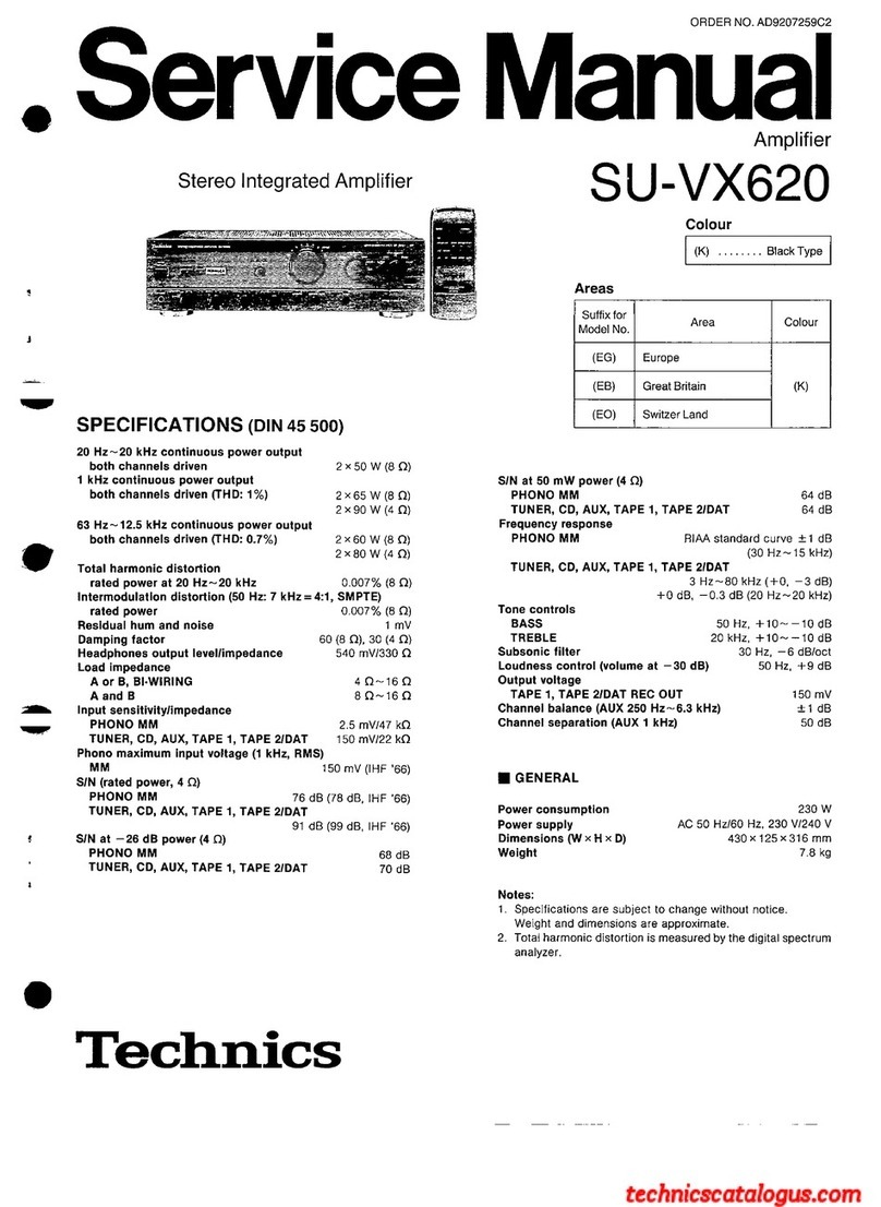
  9. Technics SU-VX620 - service User manual

Technics SU-VX620 - service User manual

U-VX620
g
CONNECTIONS
To
connect
to
each
terminals
fake
connections
to
each
component
in
the
system
by
using
tereo
connection
cables
(not
included).
(A)
(_
“PHONO”
terminals
)
Connect
to
a
turntable.
Turntable
(not
included)
OUT
‘a
R)
ePhono
input
capacitance
is
about
470
pF.
i
“GND”
terminal
This
terminalis
for
use
with
a
turntable
which
has
a
ground
wire.
Stereo
connection
cable
White
(L)
Red
(R)
VOLT
ADJ
AC
_IN~
a3
{e
SPEAKERS
(“REMOTE
CONTROL
OUT”
terminals
_)
This
terminal
can
be
used
only
with
Technics
tape
deck
and
com-
pact
disc
player
which
have
the
appropriate
remote
control
ter-
minal.
(Consult
your
dealer
for
details.)
Proper
connection
with
remote
control
connection
cables
will
allow
control
of
some
functions
from
this
unit's
remote
control
transmitter.
Connect
to
a
tape
deck
and/or
compact
disc
player
as
shown
below.
If
a
tape
deck
is
not
being
used,
the
compact
disc
player
can
be
connected
directly
(dotted
line).
This
unit
REMOTE
G)
CONTROL
OUT
Connection
cable
for
remote
control
(Included
with
tape
—|
deck)
Tape
deck
(not
included)
REMOTE
OUT
—~
Connection
cable
for
remote
control
(Included
with
compact
disc
Ke.
player)
Compact
disc
(not
included)
_
REMOTE
Note:
For
a
compact
disc
player
with
a
remote
control
sensor
the
above
connection
is
not
necessary.
ORDER
NO.
AD9207259C2
Service
Manual
Stereo
Integrated
Amplifier
SPECIFICATIONS
(DIN
45
500)
20
Hz~
20
kHz
continuous
power
output
both
channels
driven
2x50
W
(8
Q)
1
kHz
continuous
power
output
both
channels
driven
(THD:
1%)
2x65
W
(8Q)
2x90
W
(4
Q)
63
Hz~
12.5
kHz
continuous
power
output
both
channels
driven
(THD: 0.7%)
2x60
W
(8
Q)
2x
80
W
(4
Q)
Total
harmonic
distortion
rated
power
at
20
Hz~
20
kHz
0.007%
(8
Q)
Intermodulation
distortion
(50
Hz:
7
kHz
=
4:1,
SMPTE)
rated
power
0.007%
(8
Q)
Residual
hum
and
noise
1
mV
Damping
factor
60
(8
Q),
30
(4
Q)
Headphones
output
level/impedance
540
mV/330
QO
Load
impedance
A
or
B,
BI-WIRING
4Q~16Q
A
and
B
8O~16Q
Input
sensitivity/impedance
PHONO
MM
2.5
mV/47
kQ
TUNER,
CD,
AUX,
TAPE
1,
TAPE
2/DAT
150
mV/22
kO
Phono
maximum
input
voltage
(1
kHz,
RMS)
MM
150
mV
(IHF
'66)
S/N
(rated
power,
4
©)
PHONO
MM
76
dB
(78
dB,
IHF
'66)
TUNER,
CD,
AUX,
TAPE
1,
TAPE
2/DAT
91
dB
(99
dB,
IHF
’66)
S/N
at
—26
dB
power
(4
Q)
PHONO
MM
68
dB
TUNER,
CD,
AUX,
TAPE
1,
TAPE
2/DAT
70
dB
‘Technics
Amplifier
SU-VX620
Colour
c
etntioweane
Black
Type
Areas
Suffix
for
Model
No.
Area
Colour
(EG)
Europe
(EB)
Great
Britain
(K)
(EO)
Switzer
Land
SIN
at
50
mW
power
(4
Q)
PHONO
MM
64
dB
TUNER,
CD,
AUX,
TAPE
1,
TAPE
2/DAT
64
dB
Frequency
response
PHONO
MM
RIAA
standard
curve
+1
dB
(30
Hz~
15
kHz)
TUNER,
CD,
AUX,
TAPE
1,
TAPE
2/DAT
3
Hz~80
kHz(+0,
—3
dB)
+0
dB,
~0.3
dB
(20
Hz~20
kHz)
Tone
controls
BASS
50
Hz,
+10~-—10
dB
TREBLE
20
kHz,
+10~—10
dB
Subsonic
filter
30
Hz,
—6
dB/oct
Loudness
control
(volume
at
—
30
dB)
50
Hz,
+9
dB
Output
voltage
TAPE
1,
TAPE
2/DAT
REC
OUT
150
mV
Channel
balance
(AUX
250
Hz~6.3
kHz)
+1
dB
Channel
separation
(AUX
1
kHz)
50
dB
@
GENERAL
Power
consumption
230
W
Power
supply
AC
50
Hz/60
Hz,
230
V/240
V
Dimensions
(W
x
H
x
D)
430
x
125
x
316
mm
Weight
7.8
kg
Notes:
1.
Specifications
are
subject
to
change
without
notice.
Weight
and
dimensions
are
approximate.
2.
Total
harmonic
distortion
is
measured
by
the
digital
spectrum
analyzer.
SU-VX620
m
CONTENTS
Page
Page
@BEFORE
REPAIR
AND
ADJUSTMENT...................06.
2
e@PRINTED
CIRCUIT
BOARD
DIAGRAM................
18~22
@PROTECTION
CIRCUITRY
.......
0.000
2
e@WIRING
CONNECTION
DIAGRAM
.................0.005
23
@ACCESSORIES
213.
fe
etieng
orth
eesdais
eg
gaa
wad
aye
PRES
2
e@FUNCTIONS
OF
IC
TERMINALS
.................0.0000.
24
@FUNCTION
OF
CONTROLS
.......
cee
eee
eee
3
@BLOCK
DIAGRAM.........
00...
cece
cece
eee
25
@CONNECTIONS
oo...
teen
eeenes
4~6
@REPLACEMENT
PARTSLIST
.................004
26~29,
32
e@DISASSEMBLY
INSTRUCTIONS
...........
000.
e
aes
7~11
@CABINET
PARTS
LOCATION
..................0..020008
30,
31
eMEASUREMENTS
AND
ADJUSTMENTS
................
14
@PACKAGING
.....
2.2
ccc
ete
eet
ence
nee
eens
33
@SCHEMATIC
DIAGRAM
.............
000.
12~17
m@
BEFORE
REPAIR
AND
ADJUSTMENT
(1)
Turn
off
the
power
supply.
Using
a
10Q,
10
W
resistor,
shortcircuit
both
ends
of
power
supply
capacitors
C701
and
C702
in
order
to
discharge
the
voltage.
(2)
Before
turning
on
the
power
switch
of
the
unit.
.
Connect
the
voltage
controller
to
the
primary
side.
.
Connect
the
AC
ampere
meter
to
the
primary
side
or
connect
the
DC
voltage
meter
to
the
“+B”
circuit
of
the
secondary
side.
.
Turn
the
VR
of
ICQ
(VR451
and
VR452)
to
minimum
(counterclockwise).
.
After
setting
the
output
to
zero
of
the
voltage
controller,
turn
on
the
power
switch
of
the
unit.
And
increase
the
output
of
voltage
controller
gradually.
Then,
check
carefully
whether
the
current
value
of
primary
side
become
more
than
following
value
or
whether
the
DC
voltage
of
secondary
side
is
increasing
slowly.
E.
If
the
value
of
current
is
increasing
unusually
or
the
DC
voltage
is
not
increasing,
lower
the
output
level
of
voltage
controller
immediately.
@The
current
value
of
the
primary
side
at
no
signal.
(Confirm
the
power
supply
voltage
of
each
area
and
provided
voltage
of
the
unit.)
C0OWPY
Power
supply
voltage
AC
230
V
AC
240
V
m@
PROTECTION
CIRCUITRY
The
protection
circuitry
of
the
amplifier
may
have
operated
if
either
of
the
following
conditions
is
noticed:
®@No
sound
is
heard
when
the
power
is
turned
on.
Sound
stops
during
a
performance.
The
function
of
this
circuitry
is
to
prevent
circuitry
damage
if,
for
example,
the
positive
and
negative
speaker
connection
wires
are
Note:
“shorted”,
or
ifspeaker
systems
with
an
impedance
less
than
the
When
the
protection
circuitry
functions,
the
unit
will
not
operate
indicated
rated
impedance
of
the
amplifier
are
used.
unless
the
power
is
first
turned
off
and
then
on
again.
m
ACCESSORIES
@AC
powersupply
cord
......
6.
eee
il
<RJAO0019-1K>:
(EG),
(EO)
<SJA193>:
(EB)
If
this
occurs,
follow
the
procedure
outlined
below:
1.
Turn
off
the
power.
2.
Determine
the
cause
of
the
problem
and
correct
it.
3.
Turn
on
the
power
once
again.
Remote
control
transmitter
(RAK-SU301W)
..............
1
@Batteries:
scsi.
ssiaadneaieidated
stake
da
haid
mel eee
eed
2
<RO3>
L
The
configuration
of
the
AC
power
supply
cord
differs
according
to
area.
@
FUNCTION
OF
CONTROLS
STEREO
INTEGRATED
AMPLIFIER
a
SU-VX620
[1]
Power
switch
(POWER)
[2]
Operation
indicators
(AMPLIFIER
OPERATION
MONITOR)
These
indicators
illuminate
to
indicate
the
operating
condi-
tion
of
this
unit.
VOLTAGE
CONTROL:
When
the
power
is
switched
ON,
this
indicator
illuminates
when
the
unit
is
in
the
operating
condition.
CURRENT
DRIVE:
When
the
power
is
switched
ON,
this
indicator
illuminates
after
about
4
seconds
when
the
unit
is
in
the
operating
condi-
tion.
If
an
abnormal
condition
in
the
circuitry
is
detected,
such
as
DC
voltage
appearing
in
the
output,
or
a
short-circuit
of
the
positive
(+)
and
negative
(—)
wires
from
the
speaker
ter-
minals,
the
protection
circuit
functions
and
this
indicator
will
not
illuminate.
[3]
Source
direct
switch
(SOURCE
DIRECT)
This
switch
is
used
when
enjoying
high
quality
sound
playback
such
as
that
from
a
CD.
[4]
Volume
control
(VOLUME)
[5]
Recording
selector
(REC
SELECTOR)
This
selector
is
used
to
select
the
sound
source
to
be
record-
ed
by
the
connected
first
tape
deck
and/or
second
tape
deck
(or
DAT).
[6]
Remote
control
input
indicator
(REMOTE
SELECTOR)
This
indicator
illuminates
to
indicate
the
input
source
selected
(TAPE
1,
CD
or
TUNER).
While
this
indicator
is
illuminated,
the
input
will
not
change
even
if
the
input
source
is
changed
using
the
main
unit
input
selector.
Remote
control
input
erase
button
(OFF)
This
button
is
used
to
erase
the
input
selected
on
the
remote
control
transmitter
in
order
to
select
the
desired
source
us-
ing
the
input
selector
on
the
main
unit.
Input
selector
(INPUT
SELECTOR)
This
selector
is
used
to
select
the
sound
source
to
be
heard,
such
as
a
disc,
radio
broadcast,
etc.
[9]
Headphones
jack
(PHONES)
Speaker
selector
(SPEAKERS)
This
selector
is
used
to
select
the
speakers
to
be
used.
[11]
Tone
controls
(BASS/TREBLE)
The
bass
control
is
used
to
adjust
the
low-frequency
sound
range,
and
the
treble
control
is
used
to
adjust
the
high-
frequency
sound
range.
[12]
Balance
control
(BALANCE)
This
control
is
used
to
adjust
the
left/right
volume
balance.
[13]
Loudness
switch
(LOUDNESS)
This
switch
is
used
when
listening
to
music
at
a
low
volume
level.
Auditory
perception
of
sound
in
the
low
frequency
range
falls
off
at
low
volume,
but
when
the
switch
is
set
to
the
“ON”
position,
this
deficiency
is
compensated
for,
so
that
the
full
impact
of
the
musical
performance
can
be
en-
joyed.
Subsonic
filter
switch
(SUBSONIC
FILTER)
This
switch
is
used
to
eliminate
ultra-low-frequency
noise
such
as
motor
‘‘rumble”’
and
unusual
vibration
of
the
woofer
cone
caused
by
a
warped
disc,
etc.
[15]
Mode
selector
(MODE)
This
selector
is
used
to
select
stereo
or
monaural
operation.
Remote
control
signal
receptor
(REMOTE
SENSOR)
Receives
the
signals
from
the
remote
control.
U-VX620
Removal
of
the
volume
P.C.B.
Procedure
1-2-5
Volume
knob
Volume
P.C.B.
1.
Pull
outthe
volume
knob.
2.
Remove
the
nut.
3.
Remove
the
1
screw
(@).
4,
Remove
the
volume
P.C.B.
in
the
direction
of
arrow.
Removal
of
the
input
selector
P.C.B.
Procedure
1-2-6
Input
selector
Input
selector
knob
1.
Pull
out
the
input
selector
knob.
2.
Remove
the
3
screws
(@~®).
3.
Remove
the
input
selector
P.C.B.
in
the
direction
of
arrow.
Removal
of
the
operation
P.C.B.
Procedure
132-357
B:
16mm
C:
longer
than
22
mm
Use
a
wrench
of
the
dimensions
shown
in
the
illustration
above
to
remove
1.
Pullout
the
4
knobs.
nuts.
2.
Remove
the
4
nuts.
Removal
of
the
Switch
P.C.B.
Procedure
1>2—6-8
Switch
P.C.B.
eRemove
the
1
screw
(@).
Operation
P.C.B.
Procedure
1—9
1.
Remove
the
1
screw
(@).
2.
Remove
the
V-amp
P.C.B.
in
the
direction
of
arrow.
©
(
“TUNER?”
terminals
)
Connect
to
a
tuner.
(AR)
Tuner
(not
included)
OUT
9
©
CJ
ow
CJ
©)
“CD”
terminals
)
Connect
to
a
compact
disc
player.
Compact
disc
player
(not
included)
@
€
OUT
fe
=
Cs
®
®
©)
“AUX”
terminals
)
Connect
to
a
component
such
as
a
video
disc
player
(audio
only
connectable),
etc.
Video
disc
player
(not
included)
AUDIO
OUT
DO
OY
L___J
Ld
®
(R)
©
¢
|
su-vx620
(F)
(“TAPE
1”
terminals
)
Connect
to
a
first
tape
deck.
Tape
deck
1
(not
included)
REC(IN)
PLAY
(OUT)
CO
OC
()
6)
(R)
0
(R)
(RL)
(RL)
@)(
“TAPE
2/DAT”
terminals
Connect
to
a
second
tape
deck
or
a
digital
audio
tape
deck
(DAT).
Digital
audio
tape
deck
(DAT)
(not
included)
REC(IN)
PLAY(OUT)
OC
ANALOG
©
°
(AR)
()
(R)
(Ly
(RY(L)(R)(L)
To
set
the
power
voltage
VOLT
ADJ
AC
IN
a
|
{&
ofo
OO
¢
Biya
OO
Oe
SPEAKERS
|
RS
|
Set
the
voltage
selector
to
the
voltage
setting
for
the
area
in
which
the
unit
will
be
used.
{Use
a
minus
(—)
screwdriver]
Set
the
voltage
setting
to
‘230
V”
or
“240
V”.
Note:
Note
that
this
unit
will
be
seriously
damaged
if
this
setti
ng
is
not
made
correctly.
SU-VX620
|
To
connect
to
speakers
One
pair
of
speakers
can
be
connected
to
the
“A”
terminals
of
this
unit
and
one
pair
to
the
‘‘B”
terminals,
or
only
one
pair
of
bi-
wired
speakers
can
be
connected
to
all
terminals.
(
To
connect
main
and/or
second
speakers
__)
Main
(A)
speakers
(not
included)
Second
(B)
speakers
(not
included)
Mi
Load
impedance
When
only
the
‘‘A”
or
only
the
‘‘B”
terminals
are
used:
4—16
ohms
eWhen
both
the
“A” and
the
“B”
terminals
are
used
simultaneously:
8—
16
ohms
Cc.
To
connect
bi-wired
speakers
(not
included)
+)
Note:
Connect
only
bi-wired
speakers
in
this
way.
@
Load
impedance
When
bi-wired
speakers
are
used:
4—16
ohms
@
Bi-wiring
The
treble
range
and
the
bass
range
of
the
speakers
are
con-
nected
to
the
speaker
terminals
of
the
amplifier
by
using
two
speaker
connection
cords
separately
for
each.
As
a
result
of
making
connections
in
this
way,
sound
can
be
reproduced
with
much
greater
nuance
and
detail,
with
the
feel-
ings
of
air
oscillation
and
deepness
of
sound
provided
by
an
input
source
that
suppresses
reciprocal
band-range
interference.
(Refer
to
the
operating
instructions
of
the
speakers.)
To
connect
cords
to
terminals
@
Strip
off
the
outer
@
covering,
and
twist
the
—e
5S
———
center
conductor.
10
mm
Twit
@)
Turn
completely
to
the
@
cy
left.
@®
Insert
the
wire
andturn
@)
completely
to
the
right.
Pull
the
cord
to
assure
a
proper
connection.
Note:
Be
sure
to
only
connect
positive
(+)
cords
to
positive
(+)
terminals,
and
negative
(—)
cords
to
negative
{—)
terminals.
Note:
To
prevent
damage
to
circuitry,
never
short-circuit
the
plus
(+)
and
minus
(—)
speaker
wires.
To
connect
the
AC
power
supply
cord
(included)
Connect
the
AC
power
supply
cord
(included)
after
all
other
cables
and
cords
are
connected.
AC
power
supply
cord
(included)
»>—__¢«—-
up
cal
Household
[ELWARING)
SPEAKERS
AC
outlet
©
*
Cc
(
For
Europe
)
Insertion
of
Connector
Even
when
the
connector
is
perfectly
inserted,
depending
on
the
type
of
in-
let
used,
the
front
part
of
the
connec-
tor
may
jut
out
as
shown
in
the
draw-
ing.
However
there
is
no
problem
using
the
unit.
SS
Approx.
6mm
Appliance
inlet
Note:
The
configuration
of
the
AC
power
supply
cord
differs
according
to
area.
For
(EB)
area
a
—__<"
v
41)
Household
AC
outlet
Fit
a
suitable
plug
to
the
AC
power
supply
cord.
|
su-vx620
m@
DISASSEMBLY
INSTRUCTIONS
“ATTENTION
SERVICER”
|
Some
chassis
components
may
have
sharp
edges.
Be
careful
when
disassembling
and
servicing.
ae
Removal
of
the
front
panel
ass’y
Procedure
1-2
Front
panel
controller
1.
Remove
the
7
screws
(Q@~@).
2.
Remove
the
4
screws
(Q@~@®).
(For
EB,
EO
areas)
3.
Remove
the
upper
plate.
(For
EB,
EO
areas)
1.
Remove
the
remote
switch
controller.
2.
Remove
the
3
screws
(@~®).
3.
Remove
the
front
panel
ass’y
in
the
direction
of
arrow.
H
Removal
of
the
remote
switch
controller
@Remove
the
4
claws.
@
Replacing
of
the
remote
switch
controller
1.
Turn
the
selector
knobs
to
the
arrows.
2.
Put
the
switch
slider
of
switch
to
end
and
put
in
the
remote
$102
(REC
SELECTOR)
switch
controller.
Remote
Switch
Controller
Y
Rec
selector
knob
Switch
Removal
of
the
power
switch
P.C.B.
Ref.
No.
Removal
of
the
remote
switch
4
controller
Procedure
Procedure
123
152-4
Rec
selector
knob
Ne
Power
switch
P.C.B.
Clamper
.
Puli
out
the
rec
selector
knob.
.
Remove
the
nut.
Remove
the
2
screws
(@,
@).
Remove
the
rec
earth
spring.
Remove
the
remote
switch
controller
in
the
direction
of
arrow,
1.
Remove
the
1
connector
(CP501).
2.
Release
the
cables
from
code
clamper.
3.
Remove
the
2
screws
(@, @).
Akon
SU-VX620
SU-VX620
|
Ref.
No.
Ref.
No.
10
11
Procedure Procedure
o
1—9—
10
12-11
q
5
Se
P.C.B.
angle
Removal
of
the
power
transistor
Removal
of
the
remote
sensor
P.C.B.
Procedure
1—2-9-11—
12—14—16
Power
transistor
.
x
-
Solder
point
R
te
sensor
P.C.B
Solder
point
emote
s
.C.B.
CN702A/
CN702B
(7)
Main
PCB.
1.
Unsolder
the
power
transistor.
1.
Remove
the
1
screw
(@).
2.
Remove
the
4
screws
(@~@).
2.
Remove
the
P.C.B.
angle.
; :
Eva
ewhen
mounting
power
transistor,
apply
silicon
thermal
3.
Remove
the
remote
sensor
P.C.B.
in
the
direction
of
arrow.
1.
Remove
the
1
flat
cable
(CN702A/CN702B).
3.
Remove
the
main
P.C.B.
in
the
direction
of
arrow.
compound
(RFKX0002)
to
the
rear
of
the
power
transistor.
2.
Remove
the
8
screws
(Q~@).
Removal
of
the
rear
panel
Removal
of
the
AC
INLET/VOLT
ADJ.
P.C.B.
Procedure
Procedure
1-12
1512-13
Rear
panel
Check
of
the
main
P.C.B.
Procedure
1—-2—18
Procedure
1-29-11
1214-16-17
IC
Rear
panel
ie
—
a
ee
C
Oe
‘
1.
Unsolder
the
power
IC.
:
=
r
4
GO”
Re
ee
AC
IN/VOLT
ADJ
2.
Remove
the
2
screws
(@,
@).
“9
“@
@
PCB.
eWhen
mounting
the
power
IC
and
heat
sink,
apply
silicon
thermal
compound
(RFKX0002
or
equivalent)
to
rear
of
the
power
IC.
1.
Remove
the
4
screws
(@~@Q).
1.
Remove
the
11
screws
(@~@).
1.
Remove
the
1
screw
(@).
2.
Remove
the
rear
panel
in
the
direction
of
arrow.
2.
Release
the
2
claws
of
AC
inlet
cover.
Ae
switch
f.
:
controller
Rene
Removal
of
the
phono
P.C.B.
Removal
of
the
power
transformer
14
Main
P.C.B.
e
Procedure Procedure
6 0
Main
P.C.B.
/
11214
115
P.C.B.
angle
om
SS
See
ee
IN
|
Bottom
board
ass’y
<o
=
®
3)
—
transformer
fee)
_————
aes
i}
wer
eo”
A
Front
panel
ass’y
Remote
switch
controller
CN702A/CN702B
3.
Remove
the
bottom
board
ass’y.
.
Remove
the
1
screw
(@).
.
Remove
the
P.C.B.
angle.
.
Remove
the
remote
switch
controller.
1.
Remove
the
1
flat
cable
(CN702A/CN702B).
.
Remove
the
phono
P.C.B.
in
the
direction
of
arrow.
2.
Remove
the
5
screws
(@~®@).
4.
Reinstall
the
front
panel
ass’y
to
the
main
P.C.B.
and
place
the
unit
as
shown
right.
2.
Remove
the
9
screws
(@~@®).
5.
Reinstall
the
remote
switch
controller
to
the
switch.
-~9-
-10-
SU-VX620
SU-VX620
sor
P.C.B.
sor
P.C.B.
OLT
ADJ.
former
ria
Removal
of
the
main
P.C.B.
Procedure
1—2—9—11—
12—14—-16
CN702A/
CN702B
1.
Remove
the
1
flat
cable
(CN702A/CN702B).
2.
Remove
the
8
screws
(@~®@).
pera
Removal
of
the
powe
eva
Check
of
the
main
P.C.B.
Procedure
Procedure
1—-2—9—11—
:
1—2—18
12—
14-16-17
R
Rear
panel
1.
Unsolder
the
power
IC.
2.
Remove
the
2
screws
(@,
@).
When
mounting
the
power
IC
and
heat
sink,
apply
silicon
thermal
compound
(RFKX0002
or
equivalent)
to
rear
of
the
power
IC.
1.
Remove
the
4
screws
(Q@~Q).
Remote
switch
controller
~
Main
PCB.
3.
Remove
the
main
P.C.B.
in
the
direction
of
arrow.
Front
panel
ass’y
3.
Remove
the
bottom
board
ass’y.
4.
Reinstall
the
front
panel
ass’y
to
the
main
P.C.B.
and
place
the
unit
as
shown
right.
5.
Reinstall
the
remote
switch
controller
to
the
switch.
2.
Remove
the
9
screws
(@~®).
SU-VX620
eREPLACEMENT
OF
THE
FOOT
1.
Remove
the
4
heat
melted
posts
on
the
bottom
board
ass’y
with
a
pair
of
Heat
Melted
Posts
nippers
or
similar
tool.
2.
To
replace
the
foot
(RKA0053-A)
on
the
bottom
board
ass’y,
melt
the
4
posts
with
a
soldering
iron.
Foot
:
Soldering
Iron
Bottom
Board
Ass’y
Poe
Foot
m
MEASUREMENTS
AND
ADJUSTMENTS
e
ADJUSTMENT
Control
positions
and
equipment
used.
eVolume
knob
..............
x
(Minimum)
eSpeaker
selector
..........
OFF
DC
electronic
voltmeter
(EVM)
eVOLTAGE
CONTROL
(V)
AMP.
IDLING
(ICQ)
ADJUSTMENT
1.
Test
equipment
connection
is
shown
in
figure.
(Connect
the
DC
EVM
on
both
channels.)
2.
Completely
turn
the (V)
amp.
adjusting
volumes
(VR451,
VR452)
counter-clockwise.
3.
Turn
on
the
set
when
itis
cold,
and
about
8
sec.
later,
adjust
VR451
and
VR452
so
that
the
voltage
is
100410
mV.
e
ADJUSTMENT
POINTS
|
7
iTP451(V-amp.)i
=44-=
TP451(V-amp,)
|
|
|
|
|
|
!
I
|
!
|
|
|
(RKA0053-A)
SU-VX620
|
SCH
EMATIC
DIAG
RAM
(Parts
list
on
pages
26~29.)
1
2
A
Notes:
By]
esi:
Power
switch
in
“ON”
position.
(POWER)
(4L...OFF,
m...ON)
eS2:
Voltage
select
switch
in
“240
V”
positon.
(VOLT
ADJ)
©S101:
Input
select
switch
in
“PHONO”
position.
(INPUT
SELECT)
©S102:
Rec
select
switch
in
“TAPE
2/DAT
®
1”
position.
(REC
SELECTOR)
©S201:
Mode
select
switch
in
“STEREO”
position.
(MODE)
©S202:
Loudness
switch
in
‘“OFF”
position.
(LOUDNESS)
S203:
Source
direct
switch
in
“ON”
position.
(SOURCE
DIRECT)
Cc
S204:
Subsonic
filter
switch
‘“OFF”’
position.
(SUBSONIC
FILTER)
@S501:
Speaker
select
switch
in
“OFF”
position.
(SPEAKERS)
©S801:
Remote
control
input
erase
switch.
(OFF)
e\ndicated
voltage
values
are
the
standard
values
for
the
unit
measured
by
the
DC
electronic
circuit
tester
(high-impedance)
with
the
chassis
taken
as
standard.
Therefore,
there
may
exist
some
errors
in
the
voltage
values,
depending
on
the
internal
impedance
of
the
DC
circuit
tester.
No
mark:
Power
ON
(
D
e|mportant
safety
notice:
Components
identified
by
A.
mark
have
special
characteristics
important
for
safety.
Furthermore,
special
parts
which
have
purposes
of
fire-retardant
(resistors),
high-quality
sound
(capacitors),
low-noise
(resistors),
etc.
are
used.
When
replacing
any
of
components,
be
sure
to
use
only
manufacturer's
specified
parts
shown
in
the
parts
list.
eThis
schematic
diagram
may
be
modified
at
any
time
with
the
development
of
new
technology.
):
When
D810-2
is
lighting
up
Caution!
E
IC
and
LSI
are
sensitive
to
static
electricity.
Secondary
trouble
can
be
prevented
by
taking
care
during
repair.
Cover
the
parts
boxes
made
of
plastics
with
aluminum
foil.
Ground
the
soldering
iron.
Put
a
conductive
mat
on
the
word
table.
Do
not
touch
the
legs
of
IC
or
LSI
with
the
fingers
directly.
Voltage
and
signal
line
:
Positive
voltage
line.
:
Phono
signal
line.
:
Recording
output
signal
line.
F
==>
3
4
ZY
eHoNno
circuit
RIOt
PHONO
SIGNAL
{Lch)
'k
pa
ox
sn
&
|
oT
28
}
{
JKIO!
!
[ene
Oo
“
PHONO
Bae
O
RIO
390
C105
top
cl23
25V3.3
H
+
Rid
56K
RUT
270
clo7
16V33
ae
cus
cuz
Cll?
S5600P
0.022
50V!I
IK
SU-VX620
SU-VX620
8 9
10
REMOTE
SENSOR
S102
(REC
SELECTOR)
\--+
TAPE
2/DAT
PI
4---
TUNER
2:--
TAPE
1»
2/DAT
5:
-
-
PHONO
3---CD
6:--
AUX
C109
|riz3iRi27
|Ri25
180K
390P|
68
|
12K
ov
-O.1V
[I
©) ©)
Ccil6é
CIl4
5600P
0.022
Ic
101
AN6558F
PHONO
EQ
AMP
REC
OUT
SIGNAL(Lch)
Q8o
ao,
|
UN
el.
LED
6
‘tl
+
|
|
\
I
¢
l
Rooooo
|
Pepeeee
|
al
i
|
ETA
a
ESET
COA
RE)
ESAT
ER
ESE
I7V
¥
eX
ry
CHIBI
TORTI
7
©
mote
TTT]
CNIOS
asoo~a
MAIN
UN4II
|B
|
CIRCUIT
cP103 cP104
cP105
Binks
SWITCH
CIRCUIT
a
0)
O10)
OO
QIAN
sso!
JK8O!
(REMOTE
CONTROL
:
AB
MODE
/OFF)
out
|
|
ear
of
C
INPUT
mrrpOlalolale
pleh
88T
ies
+
SELECTOR
CIRCUIT
cP80s
TUNER
wat
i
OOOO®S
Rch
©
Not
elas
iy
4
CNIO2 cPlo2
iat
R203
)—18)
(INPUT
SELECTOR)
:
ake
as
[eel
Lis.
|
C—O
1s
TAPE2/DAT
2:
-TAPET
on
T
88
1
©)
3--CD
4---TUNER
oe
ob
go
Rees
0;
{¢)
—
5:PHONO
=
6+
AUX
oe
LRch
go=-
uy
+4
S
ve
4a}
JKIO3
R205
pleh
&g
AUX
G®
R206
L
85.
ve
D810
Reh
$8t
A
LNO38568PH
JKIOG
neat
0810-3
(TUNER)
rLeh
~@
UN4219TA
REC
(OUT)
R222
pelo-2cp)
RELAY
DRIVE
~
[
Rch
-
WA
——
~@
TARE
R207
Tc
0810-I(
TAPE!
ae
Ik
Sa
[.
rl
ch
6
lest
vel
—_—_§—
oe
ae
tg
ABCDE
PLAY
(IN)
2a
RZ08
LRch
G—\
&9>
6.2
v=
R223
ora)
2
G)
JKIOS
470
rRCOlO)
©
CN
804
ruiech
Ad
aeerl
Se
NA
ae
SEE
REC
(OUT)
Rech
ca
ae
Sa
Vea
TAPE2/DAT
|
1K
rlheh
©
ago
he:
PLAY
(IN)
Rao
Le
on
Rech
88
—~12-
=43'=
SU-VX620
SU-VX620
5
6
7
8
9
10
11
12
13
14
15
REMOTE
SENSOR
CIRCUIT
$102
(REC
SELECTOR)
1+
TAPE
2/DAT
PI
.+
+
TUNER
foe
RUT
C107
--TAPE
1
2/DAT
5--
-
PHONO
27o._.
1ev33
3--CD
6---
AUX
rey
ana
CHS
cuz
ClI7
RI3I
S600P
0.022
50V!_
IK
RBIO
1K
i
Z801
C109
JRi23{R127
|RIZ5
|
ox
5
=
Ro
RCDHC-237
390P
|"ga
|
12K
|
180K
ve
28
4
Oo
(REMOTE
SENSOR)
4
OS:
REC
OUT
SIGNAL(Lch)
Q@804
iv)
agav
,
a802~804
Ic1ol
UN42I1ITA
AN6558F
LED
DRIVE
1c
802
PHONO
EQ
AMP
MNI38ISTA
RESET
¢
1c
802
N
N
o
°
oO
ClHi6é
=
ClI4
®
5600P
0.022
CIB
Ri32
SOV!
1K
——
on
|+
Ox
a
ofn
MOL
Qo
oo
zoe
8S
=
a0
-
ost
S
=k
“
an
o
fe]
-171V
:
=
Ca
Se
Pe
eae
Beate
a
\7V
I7V
E
|
M37470M2063S
L
E
i
B
MICRO
COMPUTER
x
ft
+4
(REMOTE)
e
—
aupnl
ee)
ray
aeeTy
QAO
mmm)
OKO)
OOO
@
A
BC
|
4
(S4V)
(54Vi]
(OV)
15.4)
)
ov
jov
|s54vjov
jov
fov
gov
5.6V
GI—G)
6-09-28)
G6)
C)—83—€2)—€!)
kr
©
©
¢
9
=
3
2
=
we
UN42IITA
BO"
2.
28
8
2
2
oa
RE
SE
SWITCHING
a
2G
0
(RESET)
I
ol
bE
m
n >
asoo~eil
B
a
3
Fe
=
2
23
2
UN4INITA
m
FS
eo
ee
5
FS
35
ede
By
switc
circuit
UN4IIITA
Fe
$28
28
8.8
)®)
OOO
O-@-O-O-®)
O-O-O-®)
$80!
ov
fo
Ov
(REMOTE
AB
MODE
/OFF)
x4
xy
Xt
¥
—.
=
57S
osos
oss
oO
oOo
oO
oO
4
a
x
c
A
B
rey
INPUT,
Tneos
POG)
SELECTOR
CIRCUIT
cPaos
OAS
CNI02
a
sribe
sib
svi@
BI
hizay
eee
Ueay
izav)
9809
wv
Q80s
ov
RBIS
IK
é
C
OV
a
iS
(INPUT
SELECTOR)
é
(8
Cif
.
Te,
3
OY
(0.4V)
a76!
1:
TAPE2/DAT
2:
TAPE/
en
_¢
ois
\ox
bn
et
2SD2037DEFTA
(6)
(6)
“CD
4---TUNER
oo
=o
Oo
nb
REGULATOR
(5}—6)—
5--PHONO
6
AUX
act
sar
Of
Koa
98
(
2
12.6
©
2
oak
(4}—®)
ae
(ov)
asos
2
Sous
self
UT
2007...
a80s
aNealiae
-o
Oo
(5.4
(OV)
°
6
2
TT
lok
5.4v
(REMOTE)
3
1
Y
17
oH
(a
Oa
ai
2
if
9
3
D810
genio)
Evdox)
@805,806
<
©
CNIO!
cpio!
308
6
foe
LNOS856ePH
3S
UN42IITA
88
0
2
=
AY
DRIV!
o-
eS
(0)
siol
>
R
ok
Hela
3
(TUNER)
eaes
°
Sai
ia
z
RELAY
DRIVE
34
Om
P18
@
UN4219TA
a
A
T
Cuno
=
RELAY
DRIVE
OF
0810-2
(CD)
yrs
{2-—+©)
mm
(5}
5)
DBIO~
IC
TAPE!
2SC3311AQSTA
OmnO
yo
POWER
ON
DET.
2)
}—
o
OD
>
Q763
i26vt
CO)
6.2V
oy
UN42IITA
Ce
©
POWER
ON
DET.
SH
errr)
MOO
O10)
OM
OOOIELOD
A
B
AB
c
-13-
-14-
SU-VX620
SU-VX620
16
17
18 19
20
21
22
23
24
25
1H
|
OPERATION
CIRCUIT
V-AMP
CIRCUIT
VOLUME
CIRCUIT
5
50V33
1¢401
—¢—f}
VOLTAGE
CONTROL
(V)
AMP,
0461,462
if
R301|x
|%
ae
}DLING(ICQ)
ADJ.
POINT
2SK20130Y
560
|v
13
u
CLASS
AA
AMP
S
nm
mm
mx
9
°
Po)
°
p
P451
0463,
464
«
|O
cee
Ra
Ww
2.
Leh
Reh
2SU3I30Y
=e
woe
CLASS
AA
AMP
Pri
ga
ABC
no
Oe
a]
x
0465,466
CbzOi
|
x
or
S|
2SCI685RST
(1)
a
@)
ae
oT
8
oO
m
1C@
ADu.
O
yey
me
813
)
aot
o|
©
(3)
«oz
Ee
—@}
a
6.2V
saa
mo
c462
C461
0.01
0.01
+6)
oo
me
OT
Ooms
On
$204
cd
G3
ae
a
302
(SUB
SONIC
®)
i
I
50V3.3
Beg”
FILTER)
0463
D465.
©
+
1c251
ee
MA4240MTA
{
MAI67ATA
ee
ois
6
ign
Or
eats
thio
Pt
=z
4
R215
R219
C213
Ons
Oo
1
B2P|
39P
D467
E
D466
0468
MOTOR
DRIVE
3.3K
2.7K
0.056
Mme
GS
MAIG7ATA
<8
MAIG7ATA
MAI67
ATA
fuss
eyo
y3z
a
ag
46.2V
if
-46.3V
(c251
=
S40
S
Np
SAND
R306
wx
eh
we
$202
a
ey
2)
ow
)
B8285
188
i)
(Loupnes
|s)
geo
pa)
a
ea
nN
A
xr
-
--—
=
an
+
246!
|
fey
oa62/¢,,
|
o4e4
=
1
Bo
|
23g
aca
ae
=
-
|
stereo
=——mono
|
|
ot¢$
Son
|
oxe
oxu
t
«
Q465
Q466
D462
ry
STA
10301
mot
ese
$
23V
0
-2.4V
of
-24v
2.3v
[9]
|MaazaoimTa
4
L——}4--—4
L_;4--—
UPC4570C
a
ai
as
V2
_
C2
iS
M
TONE
AMP
Se
Y
3
QO)
a
-1.8V
bs
o
<
=
9
AF)
c2i4
R212
25
es
oS
0.056
56K
88
32
a)
cP202
Ped
ww
q
o
o
(\)
NODMOOM
(XD
OBDAIOQOOO®
(2)
of
By
cN402
cNaot
iS
xo
aX
|
oN
aa
(4)
R216
R220
S
3.3K
2.7K
an
(6)
°
+
mo
eery,
cN404
457,458
459,460
2SC263IRSTTA
2SAII23RSTTA
CLASS
AA
AMP
CLASS
AA
AMP
1c501
0453,454
D453
C453
S¥S
205.8
5
2SC33IIAQSTA
MAIGSTA
GEP
ie
LIMILTER
.
eral
O-OD-O)-O)
OO)
OE)
2
O~6
(—(8)
A
ca
-6.2v]
ov
ov
OV
]-44vT-14.8
ov
Tov
ov
Jov
Jov
[-13.8v
Q453
ox
Vv
2tv
tN
R46
B
B
O.2v
@
a
Nx
6
ko
a
“
Cc
Egon
4
Ox
Hig
t
o°0
ov
ont
oF¥
sya
NO
+[o>
OS
—m
t27
goo
me
oN
csxe}
O%
on
oo
al
oe
a-
0
a
3S
mn
,
oe?
lq
|i
.
s
8
+
Mol
a
ov
.0455
oSth
Racer
eg:
|
z
ISS
R528
33
é
Cpe
08
|'74wiool
e<
iy
™
5
AR530
eS
820K
=
(Pe
8
ad
c
OD
B
v2w6.8
3
og
t
|
asm
Bx
pete
Ar7s51
Ar753
R501
3.6K
2
3
an
1/2W470
1/2W
560
xs
C525
1500P
R533
1.8K
v
AR752
1
W-
“
VOLTAGE
4
1/2W470
t
[
CONTROL(V)
.
é
ASI?
el
L501
R509
AMP.
P
>
=
18P
LgyH
2Wo0.l
0455
®
|.
50
V/4wi
.
IDLING
(ICQ)
yA
Teo
ry
au
|t
20
ADJ.(Lch)
5
Sd
xfA
&
=
F
e]
os
Be
<
s
6
x
0455,456
ote
aes
Sass
|
&
=
cs
=
2SAIZ09AQSTA
>
LIMITER
R
5
2
502
3.6K
N
ox
0454
oy
<
€526
1500P
te
24V)
TN
6
E
t
iL
WA
E
3
o2y
£N
1]
a
an
R534
18K
<
m
H
t
©o
¢
W-
Pa
(s
na
TH452
08
Bot
>
||
5oo
R518
9
cst
R512
S|:
250,
5
sua}
OY
3
&
|
x]
4
vawl
go
|
'8
2wo.l
=
|5
BADCFE
+88
f
2a
%
=|]
QS
a
On
Sis
o
[sYoy
°
=
-”
ve
t
ov
~
oe
ov|
2456
oot
r
me
°o
22
|
ae
88
5]
8
°
2
R70
CN202
can
SH
0.2v
02
p
20
0°
bing
co
Ot
ais
v4awd
X
Q451,452
Frey
(7
°
1
he
on
02
a
fo
‘
nN
ral
vt
tT
Od
ART55
a>
2
exe)
Ay
2SC263IRSTTA
Sa
-2.3V
Sx
J
=
es
e,b
en
fa
ws
os
CURRENT
STABILIZER
Q452
az
tN
on
a
2%
°3
7
5
493)
Py
ta
—=l.
AR754
ART56
2
6
08
=
to)
VOWEAGE
ease
1/2W220
1/2W270
°
68P
me
a8
1
ev
oS
CONTA
ALY?
S|
Lo
So
¥
se
IDLINGUCQ)
0456
|
*
“4
s
cL
apyiRch)
MAIGSTA
6.2V
=
Eo
—
46.
3V.
-15-
—~16-
SU-VX620
SU-VX620
21
22
H
|
OPERATION
CIRCUIT
24
26
1¢40l
AN7062N
VOLTAGE
AMP
27
401,402
2SAIl23RSTTA
PRE
DRIVE
$501
(SPEAKERS)
Pa
2--A
spel
2
4--A+B/B
I-WIRING,
28
29
Q501~503
2SA992EFPTA
RELAY
DRIVE/
LED
DRIVE
SU-VX620
30
C303
100P
3.9K
LNOI4304P}
(VOLTAGE
CONTROL)
VR302-t
R313
1OOKIC)
(TREBLE)
6305
82P
-I71V
{OV
@O—®)
1K
C403
270P
R403
82K
R411
V4aw47
VR202
|OOK(G)
(BALANCE)
C3I7
Ratt
0.018
HH
$204
(SUB
SONIC
FILTER)
off
l(souRCE
C302
Re02
‘7
J
OIRECT:|
50V3.3
+
560
a
oN
bik)
rc
R570
22k
Bf
$202
(LOUDNES.
a
Ort
on
|
°
1
Lo
UPC4570C
TONE
AMP
3.9K
R56!
R563
Iwi50
1wi8o
IWIK
MAI65TA
R560 0505
R404
82K
R406
C406
2.7K
l6v22
C404
270P
VR302-2
R314
1O0K(C)
(TREBLE)
Na
oe
ox
mod
«oo
£2-
C4i4
TP
4+
R562
R564
'WwI5O
[WI80
1K
0402
MAI67ATA
R559
Wik
C318
R312
0.018
Swe
0603
ILNOI8304P
Ww
(CURRENT
DRIVE)
59,460
SAII23SRSTTA
ASS
AA
AMP
1c501 CP501
SVi3205B
POWER
AMP
46.3V
-46.4v
D501
at
e
=
i)
JK
502
Bo
<
HEADPHONES
oF
oa
=
=
go
a
si
AB
og
Ar751
AR753
R501
36K
=
(POWER)
1/2W470
1/2
560
€525
ISO0P
R533
1.8K
a
a
|
4
AR752
me
les
ao
|
\/2W470
%
own
SoHo
Oo
O)|
4
re
<
&3
Ses
°6
+
=
R5I7
csi
L501
R509
R511
ARSI9
=
=
S|
os
18
P
gut
2wo.l
2W0.!
1/2W6.8
08
ra
3}
V/4wi
sa
FO
lwo
wb
Po
A
|
~
[ms
TS
BO
oBe
= =
i
Mr-—-
oO
2)
t
«
o
rn
eS
|
Pad
88
ne
go
6
3O4
B
=
3aF
ra
a
oo
ns
=
oe
«
=
A
AC
IN/VOLT
ADJ.
CIRCUIT
me]
an
|a
_8
S
>
ty
os
R502
3.
aa
oor
Zz
O>
saa
oo
Sel
as
5
€526
1500P
2
fe
RAK:
Ap709
x
.
|
wa
R534
1.8K
MAIG5TA
-
v
©o
[
an
ms
<
S|
soa
R518
c5i2
es
AC230/240V
ai
=
Z
yaw
¢o
|
18P
zs
7
tie
a
(50/60H2)
rH
=
fed
OS
Ns
Row
-
=
em
#5
~
st
&
a
Py
z
on
SIT
o
o
<q
-
no
oe)
86
les
oye
Aovol
E701
BRO
bard
ele
P3000LF
a
as
=
°
1/2W270
gos
S3
D702
i]
ce
Be
P3000LF
iS
*62'6
s2
AR754
AR?56
ot
<j
&
eN
Weg:
(VOLTAGE
AD)
1/2W220
1/2W270
CN702A
~16-—
SU-VX620
SU-VX620
SU-VX620
|_|
PRINTED
CIRCUIT
BOARD
DIAGRAM
(Parts
list
on
pages
26~
29.)
1
2
3
4
5
6
7
8
9
10
REMOTE
NER
cD
AUX
TAPE
|
TAPE2/DAT
controL|
Uo
L
r—{rare
i}
pone
PHONO
PC.B.(REPI437A-S)
OUT
(REC(OUT))
(PLAY(IN))
(REC(OUT)J
(PLAY(IN)}
A
B
MAIN
PC.
B.(REPI436A-M)
SWITCH
PC.B.
(REPI437A-S)
VOLUME
PC.B.
ae
(REP1437A-S)
($102)
[REC
SELECTOR]
[:
-
TAPE
2/DAT
P|
3----CD
5----PHONO
2----TAPE
lp»
2/DAT
4----
TUNER
6----AUX
]
Cc
INPUT
SELECTOR
PC.B.(REPI437A-S)
D
E
(SIO1)
en
TAPE2/DAT
2---TAPE!
F
INPUT
co
4---TUNER
SELECTOR
|
are
San
Serena
|
5---PHONO
6---AUX
|
~18-
-19-
SU-VX620
SU-VX620
5
6
7
8 9
10
1
12
13
14
sa
0
|
PHONO
P.C.B.(REPI437A-S)
VreMP
Re
BCRe
Ria
s7a:S)
='R
CU
oma
po
atl
chy}—
4
UME
PCB.
1437A-S)
(sioz)
|
REC
SELECTOR
|
----
TAPE
2/DAT
PI
3----CD
5----
PHONO
“TAPE
|»
2/DAT
=
4----
TUNER)
6
----
AUX
PyrAz451
|
Sik
ites
Pte
at:
aes
VOLTAGE
CONTROL
(V)
AMP.
IDLING
(ICQ)
ADJ.
INPUT
SELECTOR
PC.B.(REPI437A-S)
REMOTE
SENSOR
PC.B.(REPI437A-S)
(S101)
INPUT
3--CD
4---TUNER
SELECTOR
Bree)
ee
PHONG
6---aux
|
={9=
#26
=
16
17 18
J
AC
IN/VOLT
ADJ.
P.C.B.
(REP1437A-S)
AC
IN
(So7/conr
)
VOLTAGE
ADJ.
POWER
SWITCH
PC.B.
(REPI437A-S)
ee
es
19
(REPI437A-S)
SU-VX620
SU-VX620
(REP1I437A-S)
Ca
ce
Cathode
20
1SR35200TB
MA165TA
MA167ATA
MA29WATA
OPERATION
PC.B.
(REP1437A-S)
SUBSONIC
FILTER
[LOUDNESS
|
ESS
21
22
AN6558F
8
Pin
UPC4570C
8
Pin
AN7062N
18
Pin
MA4036MTA
MA4068MTA
MA4082MTA
Ca
DS
Cathode
A
BALANCE
SOURCE
DIRECT
eTerminal
guide
of
IC’s,
tansistors
and
diodes.
23
M37470M2063S
2SA992EFPTA
2SA1123RSTTA
2SC1685RST
2SC2631RSTTA
MA4160MTA
MA4240MTA
Ca
5a
Cathode
A
1SS291TA
Ca
54
Cathode
A
TREBLE
A
$V1I3205B
2SA1309AQSTA
25C3311AQSTA
UN4111TA
UN4211TA
UN4219TA
P300DLF
Ca
a
Cathode
22
-
24
25
BA6218
MN1381STA
\LZ
a5
2SD2037DEFTA
2SK20130Y
2SJ3130Y
LNO14304P
LNO18304P
Anode~
4
Cathode
[---B
2-0
3--OFF
[SPEAKERS
|
Perec
4
PREAKER?
SU-VX620
SU-VX620
@
WIRING
CONNECTION
DIAGRAM
m@
FUNCTIONS
OF
IC
TERMINALS
(IC801:
M37470M2063S)
TaPe2/DaT
|
[TaPeE!|
[Aux
[TUNER]
|
REMOTE
fay
7
ie
T
r——_{
SPEAKERS
}_
(REC(OUT))
(REC(OUT))
CONTROL
Pin
|
Terminal
;
Pin
|
Terminal
.
{ichr
{Roh}
CPLAY(IND]
|
CPLAY(IN))
[co]
OUT
No.
Name
ie
paged
No.
Name
uO
Function
Mm
m
nl
m
iz
S
A
—}-——
P17/SRDY
Connected
to
GND.
18
RESET
|
Reset
signal
input.
B
|
MralW
soe
wy
P16/CLK
Remote
control
signal
output.
19
|
P30/INTO
|
Back-up
detector
signal
input.
3
|
P15/SOUT
20
P34/INTI
|
Remote
control
receiving
signal
input.
4
P14/SIN
—
Not
used.
21
|P32/CNTRO
|
POWER
switch
input.
3
5
P13/TI
&
P33/CNTRI
|
SELECTOR
MODE
switch
input.
6
P12/TO
8]:
P40
Sf
i
7
P11
Connected
to
GND.
—.
Connected
to
GND.
24
P41
—
o|9
8
P10
z
:
7
1
mae
Poo
O
SELECTOR
LED
(TUNER)
drive.
Of:
*
eon
Level
encoder
volume
control
a
O
signal
output
26
PO1
oO
SELECTOR
LED
(CD)
drive.
cP106
10
P22/IN2
;
as
re
27
P02
oO
SELECTOR
LED
(TAPE
1)
drive.
11
P21/IN1
——
SS
GE
Connected
to
GND.
28
P03
Oo
SELECTOR
RELAY
1
output.
12
P20/INO
—
29
P04
oO
SELECTOR
RELAY
2
output.
[i
]-7]
13
VREF
I
Reference
voltage
input.
eNom
cnrees
30
POS
oO
SELECTOR
RELAY
3
output.
14
XIN
|
Connected
to
ceramic
oscillator.
31
PO6
15
X
OUT
O
—
—
Connected
to
GND.
Ss
a
-
32
P07
16
Vss
—
GND
terminal.
|
H
DEER
ATION
C8,
ne
Vec
—
Power
supply
(+5
V).
(In
cp404
wsol
[10]
|
C
cn404_)
LJ
SWITCH
|
J
Exe
IN/VOLT
ADJ.
P.C.B.
(s2)
INPUT
SELECTOR
P.C.B.
SOLDER
SIDE
SOLDER
SIDE
TI
(Power
transformer
)
SOLDER
SIDE
3)
4)
@)
293)
=
—24-
m@
BLOCK
DIAGRAM
SU-VX620
[Risa
|
uPcas7oc
Ca)
G®
S101
Lexie)
)
(INPUT
s2ol
TONE
AMP
dots
SELECTOR)
(MODE)
6
ee
Me
=
Mn
®
@®
>
(7)
phono
!
stereo
VR201-1
Soon
PHONO
(©
2
>
Y
ain
|
{VOLUME,)
3p
oe
(
SUBSONIC
FILTER}
o
¢
ep
|
mone
Q
{5)
-_
ott
\
2
>
>
Oo
UPC4570C
\
on
1C101
batt
}
VR301,302
on
PHONO
EQ
AMP
1
|
tees
Treble
f°
|
»—<
|
$202
|
BALANCE)
(LOUDNESS)
j
|
Boss
aN
$203
Q
Cott
‘
jx,
|
|
(SOURCE
s
aux
¢
|
DIRECT)
MOTOR
MNI3BISTA
tuner
|
nen
-
;
G3
a
Sees
1C802
ae
cE
RESET
SIGNAL
GENERATOR
og
t
t
fee
ee
re
MOTOR
DRIVE
7
1
|
{
topel
|
|
TAPE!
4
~
aptere
|
PLAYAIN)
|
tape
2
|
|
TAPE2/DAT
;
DAT
¢
|
j
areal
os
cla
cic)
|
es
Ua
DQ
ame
4
|
Reference
|
voltage
2
6 .
—o
L--____
z80l
805,806,807,
0809,810,81!
Q801,0803
REMOTE
SENSOR
am
Relay
drive
$80!
pass
SS
Sas
Cinput
3
(REMOTE
MODE
/OFF
)
selector)
pas
See
tH
oI:
|
cpa
bod
OO
LTE
o
oO
Oo
gl
-
3
=
T
otrtnmnm
na
°
he
Sle
Sls
eeeez
&
REE
N]
SN
=
w=
ss
SI3
9808
|
no
8
x
#2
e}
|_|
4/8
e}s|
|4]8
REMOTE
a
2
”
ms
~/2|
2/0)
32
~/2]
3/5)
813
CONTROL
a
o
8
atk
6
O7hs
e}"h
o
onde
OUT
6a6
°}
°}
Y
m
POIY
eget
eR
tere
“ 9
wi
PO29
TAPE!
$102
$s
$
REC(OUT)
(REC
SELECTOR)
Con
a
es
16
]I7
13
M37470M2063S
TAPE
2/DAT
ICé
REC
(OUT)
¢3
@®
micko
COMPUTER(REMOTE)
0401
$
ANT7062N
1C401
+
VOLTAGE
AMP
ie
de
8
)
(6)
(
)
r
Ho
ah
eg
=r
045310454)
evis5068
[
Limiter
|
=
fea
|
Current
|
of
mirror
OS
0457,461
POWER
AMP
|
Ju
Q40)
ae
(0
458,462)
(8)
Class
AA
o-7-0
re
HEADPHONES
rl
i
as
aes
r
7
(2)
|
2
5
|
1
Pop
|coscode
9
(16)
Ps)
Brige
’
é
:
13)
yo
—¢8)
(9466)
133
[
Bios
|
Y
network
wT
ia
|
ba
5
|
A
]
0459,
463
[
4
|
|
{0460,464)
|
|
4d
|
|
SPEAKERS
[Orr
o
oe
on
oe
3
amp
|
|
@
5
|
o
(
)indicates
pin
a
AN
|
|
8
No.
of
right
channel.
0
045510456)
|
|
ro
|
3
;
ra
|
&
Q45!
Current
(0452)
|
stobi
050I~
503,
Relay
drive
|
050In,503
\
$501
“LED
drive
|
SpEAKERS)
$I
7-3
(POWER)
FI
[TTT
TT
BOI
704
(CURRENT
ORIVE
}
0602
&
0752,753
(VOLTAGE
CONTROL)
AC230V/240V
{50/60Hz)
C8)
s2
@
{VOLTAGE
AD\.}
0705
0761,
076i
Regulator
230W
[Regulator
|]
+8)
240v o709
ae
gl
af
4
Power
supply
cont.
—~25-
SU-VX620
m@
REPLACEMENT
PARTS
LIST
Notes:
‘Important
safety
notice:
Components
identified
by
A
mark
have
special
characteristics
important
for
safety.
Furthermore,
special
parts
which
have
purposes
of
fire-retardant
(resistors),
high-quality
sound
(capacitors),
low-noise
(resistors),
etc.
are
used.
When
replacing
any
of
components,
be
sure
to
use
only
manufacturer's
specified
parts
shown
in
the
parts
list.
“The
parenthesized
indications
in
the
Remarks
columns
specify
the
areas.
(Refer
to
the
cover
page
for
area.)
Parts
without
these
indications
can
be
used
for
ail
areas.
“Remote
Control
Ass'y:
Supply
period
for
three
years
from
termination
of
production.
|
Part Name
&
Description
Part
Name
&
Description
Remarks
1SR352001B
|
DIODE
MAL65
DIODE
MA4160M
DIODE
MAAO82MTA
[DIODE
MA4068M
DIODE
1ss291TA
[DIODE
MAl65
«(DIODE
LNO38568PH
|
DIODE
(LED)
INTEGRATED
CIRCUIT
(S)
ANG558P
1.
C,
PHONO
EQ
AMP.
[BA6218
|1.
C,
MOTOR
DRIVE
[upcas70c
1.
C,
TONE
AMP.
/AN7O62N
1.C,
VOLTAGE
AMP.
SV13205B
|.
C,
POWER
ANP.
'M37470M2063S
|1.
C,
MICRO
COMPUTER
MNI3BISTA
{1.
C,
RESET
a
oe
[Variable
RESISTOR
(S)
EUWMHXOO1B15
|V.R,
VOLUME
CONTROL
EVJO2QFA2G15
|V.
R,
BALANCE
_[EVJYAIFAZC15
|V.
R,
BASS/TREBLE
CONTROL
EVNDXAAQOBI3
VR,
1CQ
ADJ.
r
Soap
TRANSISTOR
(S)
|
1
'2SAL123RSTTA
TRANSISTOR
2SC2631RSTIA
|
TRANSISTOR
:
|2SC3311A-Q
[TRANSISTOR
2SA1309A-R
|
TRANSISTOR
2SC2631RSTTA
|TRANSISTOR
J2SAL123RSTTA
|
TRANSISTOR
28K20130Y
[TRANSISTOR
]28J3130Y
TRANSISTOR
“J2SC1685RST
[TRANSISTOR
2SA992EFPTA
|TRANSISTOR
2SD2037DEFTA
{TRANSISTOR
2SC3311A-Q
|
TRANSISTOR
juNazi1
[TRANSISTOR
UN4211
TRANSISTOR
UN4219TA
_|
TRANSISTOR
UN4211
TRANSISTOR
'UN41
11
TRANSISTOR
THERMISTOR
(S)
/ERTD27HL104T
|
THERMISTOR
~
JERTD22GL2517
|THERMISTOR
|
wet
|
See
[COMPONENT
COMBINATION
(S)
t
|
RCDHC-237
REMOTE
SENSER
i
COIL
(S)
+
SLOZ650MH49
[COIL
ELEXTIROKA9
[COIL
SLayisc-10
[COIL
[ELEPK2R2MA
[COLL
ELEXTIOIKA9
COIL
DIODE
(S)
4
MAIG7
|DIODE
MA4036MTA
[DIODE
MA165
DIODE
MA2SWA
DIODE
MA165 DIODE
WA4240H
DIODE
MA167 DIODE
MA165 DIODE
MA4160M
[DIODE
MALG5
DIODE
LNO14304P
[DIODE
(LED)
LNO18304P
|
DIODE
(LED)
P300DLE
DIODE
TRANSFORMER
S)
RTPINSBO14-W
|
POWER
TRANSFORMER
|
OSCILLATOR
(S)
EFOGC4004TA
{OSCILLATOR
[FUSE
(S)
XBA2C25TBO
=|
FUSE
SWITCH(ES)
—~26-
Part
Name
&
Description
Part
No.
Part
Name
&
Description
SU-VX620
SU-VX620
ESB8249V
SW,
POWER
FCI,
2
TEYF52BC
FUSE
HOLDER
ESD26200A
ISM,
VOLTAGE
SELECTOR
RSR6BO02-
J
SW,
INPUT
SELECTOR
RELAY
(S)
RSS6D001
SW,
REC.
SELECTOR
ESB68137
SW,
MODE
RL201-203
RSYO014M-0
“TRELAY
ESB68113
SW,
LOUDNESS
RL501,
502
RSY0013-0
RELAY
TESB68137
SW,
SOURCE
DIRECT/SUBSONIC
RL503
RSYOO14M-0
RELAY
RSR4B004-A
SW,
SPEAKER
SELECTOR
EVQZ1405R
SW,
(REMOTE
MODE)
OFF
[NAGK(S)
CONNECTOR
(S)
$JS9231-1B
TAC
INLET
SJF3057-9N
PHONO
JACK
RJUOO3KOLOM1
SOCKET
(10P)
SJF3068N
RJUGO3KOOSM1
SOCKET
(8P)
SJF3069N
RJUQS7#007
SOCKET
(7P)
SJF3069N
[RJUOS7#O09
SOCKET
(SP)
SJF3069N
RJUOO3KO10M1
SOCKET
(10P)
|RJH4801-1
RJUOO3KOO6M1
|SOCKET
(6P)
QUA045520-A
RJUOGSWOST
SOCKET
(9P)
RJJ33TRO1
REMOTE
CONTROL
OUT
RJUGO3KO10M1
SOCKET
(10P)
RJUGO3KO08M1
|SOCKET
(8P)
RJUO63WO7T
RJUGESWOST
RJUGO3KOO6M1
‘SOCKET
(7?)
+
SOCKET
(9P)
SOCKET
(6P)
RJUOS7W004
es
SJS50581BB
RJS1A1703
RJTOOSKO10-1
RJTOO3KOO8-
1
RJTOS7WO07-1
SOCKET
(5P)
SOCKET
(4P)
CONNECTOR
(3P)
CONNECTOR
(10P)
TEST
POINT
(S)
TUNER
CD/AUX
TAPE1
TAPE2/DAT
SPEAKER
TERMINAL
BOARD
HEADPHONES
JACK
+
TEST
POINT
CONNECTOR
(8P)
CONNECTOR
(7P)
RJTOS7O0S~
1
CONNECTOR
(9P)
ft
RJTOO3KO10-1
CONNECTOR
(10P)
|RJTOOSKOO6-1
CONNECTOR
(6P)
RJTOG3WOST
CONNECTOR
(9P)
RJTOO3KO10-1
CONNECTOR
(10P)
SJT30345JQ
CONNECTOR
(3P)
RJTOOSKOO8-
1
CONNECTOR
(8P)
RJTO63WO7T
CONNECTOR
(7P)
RJTOGSWOST
CONNECTOR
($P)
RJTOOSKOO6-
1
CONNECTOR
(6P)
SJT30549BB1
CONNECTOR
(SP)
mt
EARTH
TERMINAL
(S)
[sus227
TRANSISTOR
SPRING
SMC1009
SHIELD
PLATE
SNE1004-1
GND
PLATE
SNE1004-1
+
GND
PLATE
SNE1004-1
GND
PLATE
FUSE
HOLDER
(S)
-27-
|
Notes
:
*
Capacity
values
are
in
microfarads
(uF)
unless
specified
otherwise,
P=Pico-farads
(pF)
F=Farads
(F)
|
*
Resistance
values
are
in
ohms,
unless
specified
otherwise,
1K=1,000(OHM)
,
1M=1,
000k
(OHM)
Part
No.
Values
&
Remarks
ERDS2TJ362T
Values
&
Remarks
1/4W
3.
6K
ECQBIHSE2JF3
Values
&
Remarks
S0V
5600P
RESISTORS
ERDAF
2VJ121T
1/AW
120
|ECEA]
KAD
108
o0V
WU
mh
ERDS2TJ392T
1/48
3.
9K
ECQBIHA72JF3
SOV
4700P
+.
1/4W
ERDAF
2VJ121T
1/4
120
ECKRIHIO3ZF5
|
s0V
0.
01U
1/4
ERE
2EXKRIOV
Ww
O01
~|ECEAIEKA3R3B
25¥.
3.
3U
1/4W
ERDAF
2VJ100T
i
1/40
10
“TECCRIHIOIKS
50V.
100P
T
1/44
ERDAF
2VJ
1ROT
1/48
1
ECBT1H101KB5
[
SOV.
100P
ERDS2TJ271
|
1/4W
ERDSLFVJ6R8T
1/68
TECCRIHLO1KS
SOV.
100P
ERDS2TJ680T
|
1/4W
ECQVLHS63JM3
SOV
0.
O56U
ERDS2TJ184T
|
1/4¥
4
ERDS2TJ223
ERDSIFVJ100T
|
1/2W
10
,
1/4W¥
22K
ECBT1H271KB5
S0V-270P
ERDS2TJ123
1/4W
ERDS2TJ824
1/4W
ECBT1H181KB5
s0¥
=
-180P
ERDS2TJ563
|
1/4W
ERDS2TJ124T
1/4W
ECQVIHS63JM3
SOV
0.
OS6U
ERDS2TJ102
1/4W
ERDS1FVJ682T
1/2W
ECEAQJKA101B
6.3V—
100U
ERDAS3G102T
|
1/4W
ERDSLFVJ100T
1/2"
10
ECQV1H104JM3
50V.0.1U
TERDAS3G563T
|
1/4W
TERDS2TJ182
ECALHPXS3R3B
SOV.
3.
U
_[ERDS2TJ
183T
|
1/4¥
ERGISJS61E
W560
ECCRIHIO1KS
SOV.
100P
ERDS2TJ332
1/4W
ERG1SJ102E
IW IK
ECBT1H820KB5
SOV.
82P
ERDS2TJ824
1/48
ERGISJIS1E
W150
ECALHPXS4R7B
SOV.
4.
7U
1/40
ERDLS2VJ272T
ERGISJI81E
W180
ECBT1LH390J5
eee
s0V.-39P
ERDS2TJ471
1/4W
ERDS2TJ223
T1/4w
22K
/ECAICPXS100B
16Y——10U
ERDS2TJ824
ERDS2TJ221
1/4¥
220
TECQV1H823JM3
ERDS1FVJ100T
ERDAS3G561
ERDAF
2VJ6R8T
1/4W#
6.8
ECQB1H153JF3
ERDAF
2VJ470T
1/4W
47
ERDS2TJ823T
ERDS2TJ222
ERDS2TJ224T
ERDS2TJ100
ERDS2TJ392T
ERDSLFVJ471T
ERDS2TJ223
ERDSLFVJ561T
ECQB1H183JF3
1/4W
2.
2K
ECQBLH222JF
3
—
1/4W
10
ECBTIE2232F
1/2¥
=
470
ECBT1H121KBS
1/2W
560
ERDS2TJ102
ERDSLFVJ221T
1/2W
220
|
ECALHPXS3R3B
a
ie
ECCRLH271K5
ERDS2TJ392
ERDS1FVJ271T
1/2W
270
ECALCPXS220B
SOV
0.
082U
SOV
0.
015U
SOV
0.
018U
SOV
2200P
25V
0.022U
16V..22U
ERDAS36392T
Terps2TJ102
1/4¥
ik
ECBT1H820KB5
SOV
-82P
ERDAS3G6223T
ERDS2TJ103
1/4¥
10K
ECBTIH150J5
SOV.
15P
ERDS2TJ183T
jERDS2TJ102
1/4¥
1K
ECBALH681KB5
30V
680P
ERDS2TJ122
ERDS2TJ103
/4W
10K
ECCV2H070D
|
soov.
7?
ERDS2TJ8231
|
ERDS2TJ102
/4W
IK
ECQBLHLOZJF3
SOV
1000P
ERDAS36272T
ERDS2TJ223
1/4¥
22K
ECBTLHIOZKBS
SOV
1000P
ERDAS3G823T
ERDS2TJ102
1/48
1K
ECBTIE2232F
|
25V
0.
022U
ERDS2TJ361
ERDS2TJ391
1/4¥
390
ECKRIH103ZF5
|
sov_
0.
ou
ERDAF2VJ470T
ERDS2TJ102
Taw
1K
ECKR1H333ZF5
SOV
0.033U
ERDS2TJ473
ERDS2TJ104
1/48
100K
ECCV2H680K
s00V
=
G8P
ERDAF2VJ472T
ERDS2TJ103
1/4¥
10K
ECEALHKASR3B
SOV.
3.0
ERDAF2VJ151T
ECKR2H1032U
S00V
0.
O1U
ERDAF2VJ271T
|
CAPACITORS
ECAOJPXS101B
T6.3y
1000
ECQVIH473JM3
0V
0.
047U
~TERDS2TJ8237
|
aoe
ECKWNS103ZVS
s00V
0.
01U
ae
ECEAQJKA101B
ae
6.3¥
—
100U
ERDS2TJ223
ECBT1HI81KB5
30V—-180P
ECALHM470B
s0V47U
ERDAF2VJ101T
ECBTIH1O0J5
a0V«10P
ECEALHNIO0SB
|
50V.
10U
AN
ERDAF2VJ182T
ECEALCKA330B
16V.
330
ECBT1H180J5
o0V.
1
8P
ERDAF2VJ2R2T
ECBT1H391KBS
SOV
390P
ECQVIHA73JM3
|
SOV
0.
047U
ERDAF2VJ151T
ECQB1H223JF3
a0¥
0.
022U
—
28
-
ECOBIHIS3JE3
|
90V
0.0150
Qa
oo
e
=
fo
=]
=
SU-VX620 SU-VX620
SU-VX620
|
Notes
:
*
Capacity
values
are
in
microfarads
(uF)
unless
specified
otherwise,
P=Pico-farads
(pF)
F=Farads
(F)
|
Remarks
*
Resistance
values
are
in
ohms,
unless
specified
otherwise,
1K=1,
000(OHM)
,
1M=1,
000k(OHM)
Values
&
Remarks
:
ECBT1H102KB5
IN
TECOBIHIS2JF3
|
Values
&
Remarks
.
No.
Values
&
Remarks
ECBTIC332KR5
Yr
ERDS2TJ362T
C115,
116
|ECQBIHS62JF3
|
SOV
5600P
ECEA1JUOLOB
TRESISTORS
:
ERDAF
2VJ121T
C117,
118
|ECEAIHKAQ10B
|
50V
1U
[ECESIHV682UG
|
ERDS2TJ392T
|
C119,
120
|ECQBIH472JF3
|
5OV
4700P
[ECALIAP2206
|
ERDS2TJ102
1/4W
1K
f
ERDAF
2VJ121T
(121,122
|ECKRIHI03ZF5
|
50V
0.
01U
ECQE2104KF3
ERDS2TJ224T
|
1/4W
ERF
2EXKR10V
:
C123,
124
|ECEALEKA3R3B
|
25V
3.
3U
ECQVI1H104JM3
ERDS2TJ391
1/4W
390
ERDAF
2VJ100T
€201-204
|
ECCRIH101K5
SOV.
100P
ECALCM471B
[ERDS2TJ563
1/4¥
56K
ERDAF2VJ1ROT
|
€205-208
|ECBTIH101KB5
|
5OV
100P
ECEA1HKAO
10B
|
ERDS2TJ271
1/48
270
,
JERDS1EVJ6R8T
|
-
C209,
210
|
ECCRIHIO1K5
50V.-100P
|ECALCM102B
iN
5
|ERDS2TJ680T
1/4W
68
:
ERDSIFVJ100T
C213,
214
=
|ECQVIHS63JM3
|
SOV
0.
056U
ECAIEPXS470B
“TECEAICKALOLB
ECBTIE1032F
[ECEAIAKA470B
|
ECADJM102B
ECBTIE1032F
|
ECEAQJKALOIB
|
ECBT1H101KB5
ECEAIHKA2R2B
|
ECEAIHKAR47B
ECBTIE1032F
ECEAICKA220B
“TeRDS2TJ184T
|
1/4W
ERDS2TJ223
c2i9,
220
|ECBTIH271KB5
|
SOV
270P
ERDS2TJ123
|
1/4W
TERDS2J824
(221-224
|ECBTLHI81KBS
|
Sov
180P
ERDS2TJ563
|
1/4W
ERDS2TJ124T
~~
|Ic231,
232
|ECQVIHS63UM3
|
SOV
0.
056U
ERDS2TJ102
|
1/4W
ERDSIFVJ682T
C251,
252
/ECEAOJKALOIB
|
6.3V
100U
ERDAS3GIO2ZT
|
1/4W
"532
|ERDSIFVJ1OOT
253,
254
TECQVIHL04IM3
|
50V
0.
1U
ERDAS3G563T
|
1/4W
ERDS2TJ182
C301,
302
/ECAIHPXS3R3B
|
SOV
3.
U
ERDS2TJ183T
|
1/48
ERGISJSG1E
C303,
304
JECCRIHIOIKS
|
Sov
100P
ERDS27J332
|
1/4W
ERGISJ1O2E
C305,
306
[ECBTIH820KB5
|
50V
82?
ERDS2TJ824
|
1/4W
ERGISJISIE
C307,
308
|
ECALHPXSAR7B
ERDLS2VJ272T
|
1/4W
;
ERGISJIB81E
,
ECBT1H390J5
SOY
39P
ERDS2TJ47
1/4W
ERDS2TJ223
-
;
ECAICPXS100B
|
16V
100
ERDS2TJ824
1/4W
ERDS2TJ221
;
ECQVIH823JM3
|
SOV
0.
082U
ERDSIFVJ100T
|
1/2W
:
ERDAF
2VJ6R8T
:
i
ECQBLH153JF3
|
SOV
0.
015U
ERDAS3G561
1/4W
;
ERDAF
2VJ470T
;
ECQBLHI83JF3
|
SOV
0.0180
ERDS2TJ823T
|
1/4W
ERDS2TJ222
,
ECQB1H222JF3
|
SOV
2200P
ERDS2TJ224T
|
1/4W
ERDS2TJ100
:
ECBTIE2232ZF
25V
0.
022U
ERDS2TJ392T
|
1/4
ERDSIFVJ471T
;
ECBTIH121KBS
;
SOV
120P
ERDS2TJ223
ERDSIFVJS61T
|
1/2¥
;
ECAIHPXS3R3B
|
SOV
=
3.30
———$—_—_}-
—_—_
ERDS2TJ102
ERDSIFVJ221T
|
1/2W
;
ECCRIH271K5
SOV.
270P
ERDS2TJ392
ERDSLFVJ271T
|
1/2W
;
ECAICPXS220B
|
16V
=
22U
ERDAS3G392T
ERDS2TJ102
1/4¥
j
ECBTLH820KB5
|
SOV 82P
|EROAS3G223T
ERDS2TJ103
|
1/4W
P
{CBT1HS0d5
30V
ERDS2TJ183T
/ERDS2TJ102
1/4W
‘
ECBALH681KB5
|
SOV
ERDS2TJ122
;
ERDS2TJ103
1/4W
&
ECCV2H070D
S00
ERDS2TJ82
3T
ERDS2TJ102
1/4W
:
ECQB1H102JF3
|
50V
1000P
ERDAS3G27
2T
;
ERDS2TJ223
1/4W
ECBT1H102KBS
|
50VY
1000P
ERDAS3G823T
|
:
jERDS2TJ102
1/4
ECBT1E2232F
25V
0.
022
ERDS2TJ561
|
ERDS2TJ391
1/4¥
ECKRIH103ZF5
|
SOV
0.
01U
ERDAF2VJ470T
ERDS2TJ102
1/4¥
:
ECKR1H3332ZF5
|
SOV
0.
033U
[ERDS2TJ473
ERDS2TJ104
1/48
100K
ECCV2H680K
sO0Y
=
G8P
ERDAF2VJ472T
ERDS2TJ103
1/4¥
10K
ECEALHKA3SR3B
|
S50V
=
3.
3U
ERDAF2VJ1511
|
|
;
ECKR2H1032U
|
SOOV
0.
01U
ERDAF
2VJ271T
CAPACITORS
ECAQJPXS101B
|
6.3V
100U
ERDS2TJ823T
;
ECQV1H473JM3
|
SOV
0.0470
ERDAF2VJ101T
ECKWNS1032ZVS
|
SO0V
0.01U
ECEAQJKA1O1B
|
6.3V
100
ERDS2TJ223
;
ECBT1H181KB5
[
SOV.
180P
ECA1HM470B
ERDAF2VJ101T
;
ECBTLH1O0J5
s0V
—10P
ECEALHN1OOSB
|
|ERDAF2VJ1827
‘
ECEAICKA330B
|
16V
=
33U
,
ECBTLH180J5
|ERDAF2VJ2R27
:
;
ECBTIH391KB5
|
50V
390P
ECQV1H473JM3
|
SOV
0.0470
ERDAF2VJ151T
;
ECQB1H223JF3
|
SOV
0.
022U
ECQBIHIS3JF3
;
SOV
0.
015U
ECEALHKAR47B
—
28
—
—
29-
SU-VX620
m@
CABINET
PARTS
LOCATION
1
2
~30-
eee
x
=
31
SU-VX620
SU-VX620
Ref.
No.
Part
No.
RGWO127A-K
RGWO150-K
RGWO151-K
RKMO036A-K
RKM0179-K
SNE2129-1
XTBS3+8JF2Z1
RGROLS2A-A
RGRO152A-C
RGRO152A-B
RGUOO30
RHN9O001
RFKJUVX620EG
RKAQO53-A
RMCO142
RMNO189
RSQ0022
XTB3+8JFZ
SHR415
RGKO394-A
RGKO412-K
RGKO413-K
RGKO480-K
RGLO164-C
RGLO165-C
RGUOG09-K
RGUO611-K
RGUO764-K
RMRO460-K
~~
|RMRO461-K
RMROS02
RSCO287
XTBS26+8J
|
SHE187-2
SHR9814
SJS9231A
SNE2123
SUS890
XTBS3+8JFZ1
XTW3+15T
/XTB3+20JFZ
XTB3+8JFZ
~—IXTHS3+87
XTBS26+8J
RGKO415-K
RWJ3903050Kq
SU-VX620
SU-VX620
Ref.
No.
|
Part
No.
|
Part
Name
&
Description
Part Name
&
Description
Remarks
CABINET
PARTS
RGHOI27A-K
[VOLUME
KNOB
:
~~
[RpG1342
PACKING
CASE
_s
RGWO150-K
[TONE
KNOB
;
RPNOS39
PAD
RGWOISI-K
|SELECTOR
KNOB
i.
_
XZB50X65A022
|PROTECTION
COVER
RKMOO36A-K
(CABINET
(EG)
RPQOL
4
ACCESSORY
PAD
|RKMO179-K
jeer
;
(EB,
E0)
~"TX7B24X34004
|
PROTECTION
COVER
SNE2129-1
{SCREW
—
:
X2B22X20003
|
PROTECTION
COVER
XTBS3+8JFZ1
|SCREW
i
—_
=
;
~TRGROIS24-A—|REAR
PANEL
“ie
a
ACCESSORIES
RGROI52A-C
REAR’
PANERL
(60)
|
ae
RGROI52A-B
|REAR
PANEL
TER
“eat
RAK-SU301W
[REMOTE
CONTROL
TRANSMITTER
|pGu0030
4]
_
7
-1
RKKD020-K
_|BATTELY
COVER
for
REMOTE
CONT.
“TRung0001
(NUT
re:
7
[RJADOI9-1K
[AC
POWER
SUPPLY
CORD
_|
(EG,
£0)
A
|RFKJUVX620EG
|BOTTOM
BOARD
ASS’
Y
ae
af
SJA193
AC
POWER
SUPPLY
CORD
(EB)
/\
[RKA0053-A
(FOOT
i
_
RQTI624-E
|
INSTRUCTIONS
MANUAL
(EO)
RMCO142
REC
EARTH
SPRING
_
~~
TRFKSUVX620EG
|
INSTRUCTIONS
MANUAL
(Es)
RMNO189
P.
C. B.
ANGLE
7”
Farias
INSTRUCTIONS
MANUAL
(EB)
RSQOO22
REMOTE
SWITCH
CONTROLLER
a
RQAOO13
[WARRANTY
GARD
XTB3+8JFZ
|SCREW
RQCBO169
SERVICE
CENTER
LIST
SHRA15
LATCH
_
_
ae
RGKO394-A
RING”
RGKO412-K
[SIDE
ORNAMENT(L)
RGKO413-K
[SIDE
ORNAMENT(R)
'RGKO480-K
[VOLUME
ORNAMENT
[RGLOI64-C
[ORNAMENT
=
“TRGLOIG5-C
ORNAMENT
RGUOBOS-K
|MODE
BUTTON
RGUOGLI-K
[DIRECT
BUTTON
RGUO764-K
[REMOTE
CONTROL,
BUTTON
'RMRO4GO-K
HOLDER
_
|RMRO
"HOLDER:
[spacER
RSCO287
XTBS26+8)
|
SCREW
P.C.B.
SPACER
~|sHR9814
CLUMPER
ISIS9231A
AC
INLET
COVER
'SNE2123.
‘GND
SCREW
aa
'SUS890
SPRING
XTBS3+8JFZ1
[SCREW
XTM3+15T
[SCREW
XTB3+20JF2
—
|SCREW
‘XTB3+8JF2
[SCREW
~'XTWS3+8T
SCREW
~~
XTBS26-8)
SCREW
[RFKGUVAG2OEG
[FRONT
PANEL
ASS’
Y.
/RGKO415-K
[UPPER
PLATE
RWJ39071300Q
|FLAT
CABLE
(7P)
(W702)
ee
|FLAT
CABLE(3P)
(W501)
—31-
~
32
—

Other manuals for SU-VX620 - service

3

Other Technics Amplifier manuals

Technics SU-A700 User manual

Technics

Technics SU-A700 User manual

Technics SE-A100 User manual

Technics

Technics SE-A100 User manual

Technics SU-C1010 User manual

Technics

Technics SU-C1010 User manual

Technics SU-X920DE User manual

Technics

Technics SU-X920DE User manual

Technics SU-VX800 - service User manual

Technics

Technics SU-VX800 - service User manual

Technics SU-V8 User manual

Technics

Technics SU-V8 User manual

Technics SU-V620 - SERVICE User manual

Technics

Technics SU-V620 - SERVICE User manual

Technics SU-8080 User manual

Technics

Technics SU-8080 User manual

Technics SECA-1060 User manual

Technics

Technics SECA-1060 User manual

Technics SE-HDA710 User manual

Technics

Technics SE-HDA710 User manual

Technics SU-V505 - service User manual

Technics

Technics SU-V505 - service User manual

Technics SU-CH700 User manual

Technics

Technics SU-CH700 User manual

Technics SU-Z65 - SERVICE User manual

Technics

Technics SU-Z65 - SERVICE User manual

Technics SU-Z15 - SERVICE User manual

Technics

Technics SU-Z15 - SERVICE User manual

Technics SEA1010 - STEREO POWER AMPLIFI User manual

Technics

Technics SEA1010 - STEREO POWER AMPLIFI User manual

Technics SU-G700 User manual

Technics

Technics SU-G700 User manual

Technics SU-X860 User manual

Technics

Technics SU-X860 User manual

Technics SU-A700 mk3 User manual

Technics

Technics SU-A700 mk3 User manual

Technics SU-V460 User manual

Technics

Technics SU-V460 User manual

Technics SU-V550 User manual

Technics

Technics SU-V550 User manual

Technics SU-8080 User manual

Technics

Technics SU-8080 User manual

Technics SU-R1000E-S User manual

Technics

Technics SU-R1000E-S User manual

Technics SU-A700MK3 User manual

Technics

Technics SU-A700MK3 User manual

Technics SE-9060 (X) User manual

Technics

Technics SE-9060 (X) User manual

Popular Amplifier manuals by other brands

Channel Master MicroAmp CM-7776 instruction sheet

Channel Master

Channel Master MicroAmp CM-7776 instruction sheet

Blaupunkt GTA 11250 DSP manual

Blaupunkt

Blaupunkt GTA 11250 DSP manual

Omnitronic MCS-1250 user manual

Omnitronic

Omnitronic MCS-1250 user manual

ELPRO DA210 user manual

ELPRO

ELPRO DA210 user manual

Grace ROXi owner's manual

Grace

Grace ROXi owner's manual

WEST PAM-140-P Technical documentation

WEST

WEST PAM-140-P Technical documentation

Crown FM2000A user manual

Crown

Crown FM2000A user manual

Monacor SA-200 instruction manual

Monacor

Monacor SA-200 instruction manual

Hughes & Kettner Blonde Edition manual

Hughes & Kettner

Hughes & Kettner Blonde Edition manual

Siemens SIMATRIX NEO V2 Configuration manual

Siemens

Siemens SIMATRIX NEO V2 Configuration manual

Ibanez PENTATONE owner's manual

Ibanez

Ibanez PENTATONE owner's manual

Crown XTi 1000 Specifications

Crown

Crown XTi 1000 Specifications

Sony XM-4501 operating instructions

Sony

Sony XM-4501 operating instructions

Stewart Audio AV25-2-RS232 owner's guide

Stewart Audio

Stewart Audio AV25-2-RS232 owner's guide

VHT Synergy Fryette Deliverance manual

VHT

VHT Synergy Fryette Deliverance manual

VentureCraft SounDroid user guide

VentureCraft

VentureCraft SounDroid user guide

LA Audio Electronic UB292 datasheet

LA Audio Electronic

LA Audio Electronic UB292 datasheet

Alpine MRV-M250 owner's manual

Alpine

Alpine MRV-M250 owner's manual

manuals.online logo
manuals.online logoBrands
  • About & Mission
  • Contact us
  • Privacy Policy
  • Terms and Conditions

Copyright 2025 Manuals.Online. All Rights Reserved.