manuals.online logo
Brands
  1. Home
  2. •
  3. Brands
  4. •
  5. Troy-Bilt
  6. •
  7. Snow Blower
  8. •
  9. Troy-Bilt STORM 2620 User manual

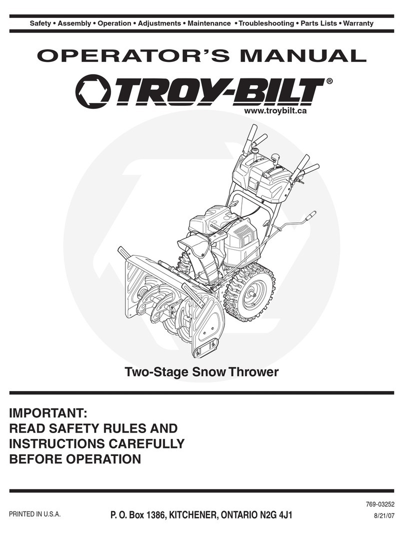
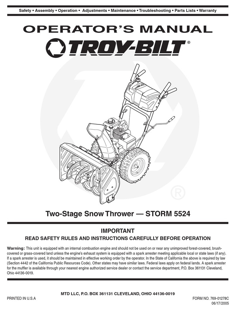
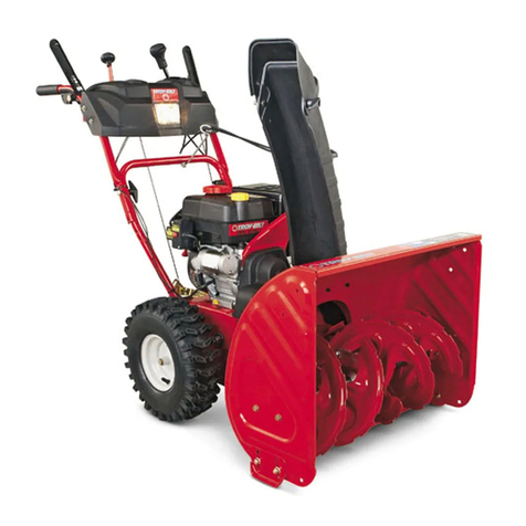
Troy-Bilt STORM 2620 User manual

Safe
OpcrtEces. Set-Up.
Operation
..Troubleshooting
. Warranty
OTRgvE
OpeRAToR's
MANUAL
Two-Stagc
SnilThruwer - Storm 2620
AwnnNlNG
REAT'
ANDFOLTOW
Att SAFETY
RULES
ANDINSTRUCTIONS
IN
THISMANUAL
BEFOREATTEMPTING
TO
OPERATETHIS
MACHINE.
FAITURETO
COMPLY
WITH
THESE
INSTRUCTIONS
MAYRESULT
INPERSONAL
INJURY.
PrintedinU5l
TROY-BILT
LLC,
p.O.
BOX
351131
CLEVELAND,
OH|O44136-0019
Form
No.769-050134
(August
5,2009)
I
I
I
I
To
The
Owner
I
I
Thank
You
Thank
you
forpurchasing
aSnow
Thrower
manufactured
by
Troy-Bilt
LLC.
ltwas
carefully
engineered
to prouio"
excellent
performance
whenproperry
operated
andmaintained.
Please
read
this
entire
m
I
tin
str
ucts
yo
uh
ow
.,:1:
;i il ::li;ff ':i:;rn,""o:l:.
"
",
maintain
your
machine.
please
be
sure
thatyou,
and
any
other
persons
who
willoperate
the
machine,
careiully
follow
the
recommended
safetypractices
at
ail
times.
Fairure
to doso
courd
result
inpersonal
injury
orproperty
damage.
All
information
in
this
manual
is
relative
to themost
recent
product
information
available
at
thetime
ofprinting.
Review
this
manual
frequentry
tofamiriarize
yourserf
with
the
machine,
its
features
and
operation.
please
be
aware
that
this
Operator,s
Manual
may
cover
arange
of product
specifications
fo,various
models.
Characteristics
and
features
discussed
and/or
illustrated
in
this
manual
may
notbe
applicable
to all
models.
Troy_Bilt
LLC
reserves
theright
to change
product
specifications,
designs
and
equipment
without
notice
and
without
incurring
obligation.
1
lf
you
have
anyproblems
o: tlrestrons
concerning
the
machine
phone
a
authorized
Troy-Brtt
ser,
ce
dealer
or
coritact
us
direc:
,
Troy-Bilt's
Customer
Support
!erephone
numbers,
website
address
and
mailing
address
can
cp
,. nd
on
thispage.
Wevranr
to
ensure
your
complete
satrsfact
o- a!
a : mes.
Throughoutthis
manual,
allreferences
:: .
;^. and
leftside
of
the
machine
are
observed
from
the
operai
. a
a
,, I on
Engine
Maintenance............... ......,..,.
20
Service...... .....22
Troubleshooting
......... .....
26
Replacement
Parts..... .....
27
Warranty.. ..........8ack
Cover
Record
Product
Information
Before
setting
up
and
operattng
your
new
equipment,
ptease
locate
themodel
plate
ontheequipment
andrecord
the
information
in
theprovided
area
to theright.
you
can
tocate
the
model.plate
bystanding
at
theoperator'iposition
and
rooking
at
thelower,
rear
section
of
the
frame.
This
information
willbe
necessary
should
you
seek
technical
support
via
our
website,
Customer
Support
Department,
orwithalocal
authorized
service
dealer.
Moorr-
NuMaen
rtrtr!!rrrr
Senrnl
NuMsen
rr!!rrrr!!r
Customer
Support
Pleose
do Nor return themachineto the
retoiler
ordealer
without firstcontoctingour
customersupport Department.
lfyou
have
difficulty
assembling
this
product
orhave
anyquestions
regarding
the
controls,
operarron,
ormaintenance
of
this
machine,
you
can
seek
herp
from
the
expertt.
cr,*J"i.-a"n" "0i,"", berow:
0 Visit
us
onthe
web
at
www.troybilt.com
0 Call
aCustomer
Support
Representative
at
(gO0)
g2g_5500
or(330)
55g_7220
0 writeus
at
Troy-Birt
LLC
.p.o.
Box
361131
.creverand,
oH .44136-0019
'l
Important
Safe
0peration
Practices
WnfrntruG! ffrissymbol
points
outimportant
safety
instn
ctbns which,
ifnotfollowed,
could
endanger
thepersonalsafety
and/or
propertyofyourself
rrd others.
Read
and
follow
all
instructions
inthis
manual
before
attempting
tooperate
this
machine.
Failure
tocomply
withthese
instructions
may
result
in
personalinjury.
When
you
see
this
symbol.
HEED
ITS
WARNING!
CALIFORNIA
PROPOSITION
65
WARNING!
Engine
Exhaust,
some
of
itsconstituents,
and
certain
vehicle
components
contain
oremit
chemicals
known
to State
of
California
tocause
cancer
and
birth
defects
orother
reproductive
harm.
DANGER:This
machine
was
built
tobeoperated
according
tothe
safe
operation
practices
in
this
manual.
As
withany
type
of
power
equipment,
carelessness
or
error
on
the
part
ofthe
operator
can
result
inserious
injury.
This
machine
iscapable
ofamputating
fingers,
hands,
toes
and
feetand
throwing
foreign
objects.
Failure
toobserve
the
following
safety
instructions
could
result
inserious
injuryor
death.
Training
1. Read.understand,
and
followall
instructions
onthe
machine
and
in
themanual(s)
before
attempting
to
assemble
and
operate.
Keep
this
manual
inasafe
place
for
futureandregular
referenceand
forordering
replacement
parts.
2. Befamiliar
*iin ullcontrols
and
their
proper
operatlon'
Know
howtostop
the
machine
and
disengage
them
q
u
icklY
3. Never
allowchildren
under
14
years
ofage
tooperate
this
machrne.
Children
14andover
should
readandunderstand
the
Instructrons
andsafe
operation
practices
inthis
manual
and
onthe
machine
andbe
trained
and
supervised
by
an
adult.
4. Neverallow
adults
tooperate
this
machine
without
proper
instructi
on.
5. Thrownobtects
can
cause
serious
personalinjury.
Plan
your
snow-throwing
pattern
toavoid
discharge
ofmaterial
toward
roads,bystanders
andthe
like.
6. Keepbystanders,
pets
andchildren
at
least
75
feetfromthe
machine
while
itisinoperation.
Stop
machine
ifanyone
enters
thearea.
7. Exercise
cautron
to
avoidslipping
or
falling,especially
when
ooerattnQ
inreverse.
Preparation
Thoroughly
inspect
thearea
where
theequipment
isto beused
Remove
all
doormats,
newspapers,
sleds,
boards,
wiresand
other
foreign
objects,
which
could
be
tripped
over
orthrownbythe
auger/impeller.
1. Always
wear
safety
glasses
oreye
shields
during
operation
and
while
performing
anadjustment
or
repairto
protect
your
eyes.
Thrown
objects
which
ricochet
cancause
serlous
injury
totheeyes.
2. Donot
operate
without
wearing
adequate
wlnterouter
garments.
Donot
wear
jewelry,
long
scarves
orotner
loose
clothing,
which
could
become
entangled
inmoving
parts'
Wear
footwear
which
will
improve
footing
onslippery
surfaces.
3. Usea
groundedthree-wire
extension
cord
and
receptacle
forall
machines
withelectric
start
engines'
4. Adjust
collector
housing
height
toclear
gravel
orcrushed
rocksurfaces.
5. Disengage
allcontrol
levers
before
starting
theengine'
6. Never
attempt
to make
anyadjustments
whileengine
is
running,
except
wherespecifically
recommended
inthe
oPerator's
manual.
7. Letengine
and
machine
adjust
to outdoor
temperature
before
starting
to clear
snow.
l'
SafeHandlingof
Gasoline
To
avoid
personal
injuryorproperty
damage
useextremecare
in
handling
gasoline.
Gasoline
is
extremelyflammableandthe
vapors
areexplosive.
Serious
personal
injury
canoccur
when
gasoline
is
spilledon
yourself
or
your
clotheswhich
can
ignite.
Wash
your
skinand
changeclothes
immediately.
a. Useonlyanapproved
gasoline
container.
b. Extinguish
allcigarettes,cigars,
pipes
andother
sources
ofignition.
c. Neverfuelmachineindoors.
d. Neverremove
gas
caporaddfuelwhiletheengineis
hot
or
running.
e. Allow
engineto coolatleast
two minutesbefore
refueling.
f. Neveroverfillfueltank.Fill
tankto no morethan7z
inch
belowbottom offillerneckto provide
space
for
fuel
exoansion.
g. Replacegasoline
capandtighten
securely.
h. lf
gasoline
isspilled,wipeit
offtheengineand
equipment.Movemachine
to anotherarea.
Wait
5
minutes
beforestartingtheengine.
i. Never
storethemachineorfuelcontainerinside
where
there
is
anopen
flame,
sparkorpilot
light
(e.9.
furnace,waterheater,spaceheater,
clothes
dryeretc.).
j. Allowmachineto coolatleast
5minutes
before
storing.
k. Neverfillcontainersinsideavehicleoronatruck
ortrailerbedwitha
plastic
liner.Always
place
containersonthe
ground
away
from
your
vehicle
beforefilling.
l. lfpossible,
remove
gas-powered
equipmentfrom
thetruck
qr
trailerand
refuelit
onthe
ground.
lf
this
isnot
possible,
then
refuel
suchequipmentona
trailer
with
a
portable
container,
rather
than
from
a
gasoline
dispensernozzle.
m. Keepthenozzle
in
contact
withtherim
ofthe
fuel
tankorcontaineropeningatalltimesuntilfuelingis
complete.
Donotuseanozzlelock-open
device.
0peration
1. Donot put handsorfeetnearrotating
parts,
intheauger/
impeller
housing
orchuteassembly.Contact
with
the
rotating
parts
canamputatehandsandfeet.
2. Theauger/impellercontrol
leveris
asafetydevice.
Never
bypass
its
operation.
Doing
so
makes
themachine
unsafe
and
may
cause
personal
injury.
3. The
control
leversmustoperateeasilyinbothdirections
andautomatically
returnto the disengaged
position
when
released.
4. Never
operate
witha missing
ordamaged
chute
assembly.
Keepallsafetydevicesinplace
andworking.
Neverrun
an
engine
indoors
or
ina
poorlyventrl3iecivea
Engineexhaustcontains
carbon
monoxide,
anodorters
anddeadly
gas.
Donotoperatemachine
whileunderthe
influence
of
alcoholor
drugs.
Mufflerand
enginebecome
hotandcancause
aburr i
nottouch.
Keep
children
away.
Exerciseextreme
cautionwhenoperating
onor
cross
^;
gravel
surfaces.
Stayalert
for
hidden
hazardsor
traff':
Exercisecaution
when
changingdirection
and
while
operating
onslopes.
Plan
your
snow-throwrng
pattern
toavoiddischarge
towards
windows,walls,carsetc.
Thus,avoiding
poss
ar.
property
damageor
personal
in.lury
causedby
arico<^er
Neverdirectdischarge
atchildren,bystanders
and
per :r
allow
anyone
infront
of
themachine.
Do
not
overload
machinecapacityby
attempting
t. :€t
snow
attoo fastofarate.
Neveroperatethis
machinewithout
good
visibilit;:' r{a
Alwaysbesureofyour
footingandkeep
a
firmholdo.'trY
handles.
Walk,neverrun.
Disengage
power
to theauger/impeller
whentransPl':'^g
ornotinuse.
Neveroperate
machineathightransportspeeds
on
slipperysurfaces.
Lookdownand
behindanduseca't
whenbackingup.
lf
the
machineshould
startto
vrbrateabnormally,
stop
the
engine,disconnect
thespark
plug
wireand
ground
rt
againstthe
engine.
Inspectthoroughly
for
damage.
Repair
anydamage
beforestartingand
operating.
Disengageallcontrol
leversand
stopengine
before
you
leavetheoperating
position
(behind
thehandles
\',
a:
untilthe
auger/impeller
comestoacomplete
stopber.'i
unclogging
thechute
assembly,
making
any
adjustme^:
I
orinsoections.
Never
putyour
handinthe
dischargeorcollector
ope' ^:!
Alwaysusetheclean-out
tool
provided
to unclog
the
discharge
opening.
Donotunclogchuteassembly
".
n e
engine
isrunning.Shut
offengineand
remainbeh,nJ
handlesuntilall
moving
parts
have
stopped
before
unclogging.
Useonly
attachmentsand
accessoriesapproved
b\ rF€
manufacturer
(e.9.
wheelweights,tirechains,cabs
etc
Whenstartingengine,
pull
cord
slowlyuntilresistance
isfelt,then
pull
rapidly.Rapid
retraction
ofstarter
cc'3
(kickback)
will
pull
handandarmtowardengine
faster
:-lr
you
canlet
go.
Brokenbones,
fractures,
bruises
orspiarl6
could
result.
lfsituationsoccur
whichare
notcovered
inthis
manue.
.r*
careand
good
judgment.
ContactCustomerSuppor:
for
assistanceand
thenameof
vour
nearestservicinqJedr.
10.
5.
11
t2
1l
13.
14.
15.
16.
lB.
19.
20.
4Secrron
2 - lruponrrnrSnreOpeRnnoN
PRAcrcEs
21.
Clearing
a
CloggcdlXrharge
Chute
Handconlact
*rth therotating
impellerinside
thedischarge
chute
rstae.nosl
common
cause
ofinjury
associated
wrlhsnow
throwers.
\ever use
your
handto clean
outthedischarge
chute
To
clear
thechute:
1 SHUT
THE
ENGINE
OFF!
2. Wait
10seconds
to besure
the
impeller
blades
have
stopped
rotating.
3. Always
use
aclean-out
tool,
not
yourhands.
Maintenance
&Storage
2.
Nevertamper
with safety
devices.
Check
their
proper
operation
regularly.
Referto
the
maintenance
and
adjustment
sections
of
this
manual.
Beforecleaning,
repairing,or
inspecting
machine
disengage
allcontrol
levers
andstop
theengine.
Waituntil
the
auger/impeller
come
toacomplete
stop.
Disconnect
the
spark
plug
wire
and
groundagainst
theengine
to
prevent
unintended
starting.
Check
boltsand
scrervs
for
proper
tightness
at
frequent
intervals
to
keep
the
machine
in
safe
workingconditron
Also,
visually
inspect
machine
for
any
damage.
Donotchange
the
engine
governorsetting
orover-speed
theengine.
The
governor
controls
themaximum
safe
operating
speed
oftheengine.
Snow
thrower
shave
plates
andskid
shoes
aresubject
to
wearand
damage.
For
your
safety
protection,frequently
check
allcomponents
and
replace
withoriginal
equipment
manufacturer's
(OEM)parts
only.
"Use
of parts
whichdo
notmeet
theoriginal
equipment
specifications
maylead
to
improper
performance
and
compromise
safety!"
Check
control
levers
periodicallytoverify
theyengage
anddisengage
properly
and
adjust,
ifnecessary.
Refer
tothe
adjustment
section
inthisoperator's
manual
for
instructio
ns.
Maintain
or
replacesafety
and
instruction
labels,
as
necessary.
Observe
proper
disposal
lawsand
regulations
for
gas,
oil,
etc.
to
protect
theenvironment.
Priorto storing,
runmachine
a
fewminutes
toclear
snow
frommachineand
preventfreezeupofauger/impeller.
Neverstore
the
machineor
fuelcontainer
inside
where
there
isanopen
flame,
sparkor
pilot
lightsuch
asa
water
heater,
furnace,clothes
dryer
etc.
Always
refertotheoperator's
manual
forproper
instructions
on
off-season
storage.
Check
fuel
line,tank,cap,
and
fittings
frequently
forcracks
or
leaks.
Replaceifnecessary.
Do
notcrank
engine
withspark
plug
removed.
14. According
tothe
Consumer
Products
Safety
Commission
(CPSC)
andthe
U.S.
Environmental
Protection
Agency
(EPAi
this
product
hasan
Averoge
lJseful
Life
ofseven
(7)
years'
or
60
hours
ofoperation.
At
the
end
of the
Average
Useful
Life
havethemachine
inspected
annually
by
anauthorized
service
dealer
to ensure
that
all
mechanical
and
safety
systems
are
working
properly
and
not
wornexcessively'
Failure
todo
so
can
result
in
accidents,
injuries
or
death'
Do
not
modify
engine
Toavoid
serious
injury
ordeath,
do
not
modify
engine
inany
way.
Tampering
withthegovernor
setting
can
leadto arunaway
engine
and
cause
it
to
operate
at
unsafe
speeds
Never
tamper
withfactory
setting
of
engine
governor'
llotice
Regarding
Emissions
Engines
which
are
certified
to comply
withCalifornia
and
federal
EPAemission
regulations
forSORE
(Small
OffRoad
Equipment)
arecertified
to operate
onregular
unleaded
gasoline,and
mayinclude
the
following
emission
control
systems:
Engine
Modification
(EM),
Oxidizing
Catalyst
(OC),
Secondary
Air
Injection
(SAl)
and
Three
Way
Catalyst
(TWC)
ifsoequipped'
fi
l'l
lr
I,N
ll
Ilt
lr
I
t
6.
7.
10
ll.
12
Spark
Arrestor
WARNING!
This
machine
isequipped
with
an
internal
combustion
engine
and
should
notbeused
onor near
anyunimproved
forest-covered,
brush
covered
orgrass-covered
landunless
theengine's
exhaust
system
isequipped
withaspark
arrester
meeting
applicable
localorstate
laws
(if
any).
lfaspark
arrester
isused,
itshould
bemaintained
ineffective
working
order
bytheoperator.
IntheState
ofCalifornia
the
above
isrequired
bylaw
(Sectio
n
4442of the
California
Public
Resources
Code).
Other
states
may
havesimilar
laws.
Federal
laws
apply
on
federal
lands.
Asoark
arrester
forthemuffler
isavailable
through
your
nearest
engine
authorized
service
dealer
orcontact
theservice
deoartment,
P.O.
Box361131
Cleveland,
Ohio44136-0019.
13.
Sscrroru
2 - ltuponrntr
Snre
Oprnnrtot.t
Pnncrtces
Safety
Symbols
Thispage
depicts
and
describes
safetysymbols
thatmay
appearonthis
product.
Read,
understand,
andfollow
all
instrucrpns
cr :ne
machine
before
attempting
to assemble
andoperate.
WARNING!
YourResponsibility-Restrict
the
useof
this
power
machineto
persons
whoread,
understand
and
follow
thewarnings
andinstructions
in
thismanual
andonthemachine.
SAVETHESE
INSTRUCTIONS!
READ
THE
OPERATOR'5
MANUAL(S)
Read,
understand,
andfollow
allinstructions
in
the
manuai
s before
attempting
to
assemble
and
ooerate
WARNI
NG- ROTATING
BLADES
Keephands
outof inlet
anddischargeopenrngs
rihrle
machrnersrunning.
There
arerotating
bladesinside
WARNING ROTATINGBLADES
Keephands
out
of
inlet
anddischargeopeningswhilemachineisrunnrng.There
are
rotating
bladesinside
WARNING- ROTATING
AUGER
Donot
put
hands
orfeetnearrotating
parts,
intheauger/impellerhousing
orchute
assembly.
Contactwiththe rotating
parts
canamputatehands
andfeet.
,2 WARNI
NG-THROWN
OBJECTS
Thismachine
may
pick
up
andthrowandobjectswhich
cancauseserious
personal
injury.
WARNING
GASOLINEIS
FLAMMABLE
Allow
the
engine
tocoolatleast
two minutes
before
refueling.
o
r{]\ WARNING CARBONMONOXIDE
Never
runan
engineindoors
orin
apoorly
ventilatedarea.Engine
exhaustcontains
carbon
monoxide,
anodorless
and
deadly
gas.
WARNING-ELECTRICAL
SHOCK
Donotusetheengine's
electric
starterin
the
rain
WARNING-HOT
SURFACE
Engine
parts,
especially
themuffler,
becomeextremelyhot
duringoperation.
Allowengine
andmuffler
to coolbefore
touchino.
Secrroru2 - InnponrnHr
SnreOpennloNPRAcncEs
I
IAssembly
&
Set-Up
I
Contents
d(rth
. C.reSnowThrower
. jne Snow
Thrower
OPerator's
\ranual
Two
Replacement
Auger
Shear
Pins
Hex
Rod
One
Product
Registration
Card
Chute
AssemblY
i
t
T
tI
Assembly
Remo,e
all
loose
parts
before
assembling.
Handle
Assembly
L Placetheshift
leverinthe
Forward-6
position
2. Obserre
the
lorverreararea
of
thesnowthrowerto
be
sure
both
cables
are
aligned
withroller
guidesbefore
pivoting
the
handleupward.
Pivotthe
handle
upward.
See
Fig.3-1
'
NOIE:
Make
certain
the
upper
ends
ofeach
cable
are
seated
proPerlyrnrtsbracket.
Figure
3-1
Secure
the
handle
bytightening
the
plasticknob
located
on both
theleftandrightsides
ofthehandle.
Remove
and
discard
any
rubber
bands,
if
present.
Theyare
for
packaging
PurPoses
onlY.
Chute
Assembly
1. Remove
cotter
pin,
wing nutand
hexscrew
fromchute
control
head
and
clevis
pin
andbow-tie
cotter
pin
from
chute
support
bracket.
See
Fig.3-2.
t. lnsert
hex
rod
intochute
control
head.
Push
rod
as
farinto
chute
control
headas
possible,
keeping
the
holes
inthe
hex
rod
pointing
upward.
See
Fig'3-3.
Chute
Control
Head
Chute
SuPPort
Bracket
/
-\
2-o
z
./
Figure
3-3
Figure
3-2
3. Placechuteontochutebaseandensurehex
rodis
positioned
underthe
handle
panel.
Installhexbolt
previously
removedbutdo notsecurewith wing nut
atthis
time.See
Fiq.
3-4.
Figure
3-4
Squeezethetriggeronthejoystickand
rotate
thechute
by
handto faceforward.Theholesin
thechutecontrol
inout
willbefacingup.SeeFig.3-5.
Nofe:The
chute
willnot rotatewithout squeezingthe
triggeronthe
joystick.
t\
A
(( >t/
V
Rotatethe
joystrck
tothe
one
o'clock
position
so
:^ll :ne
silver
indicatorarrovi
onthe
piniongear
below
tr€ (:^i'.1
panel
facesupward.
See
Fig.3-6.
NotelThe
joystick
wrllbe
angledslightlytothe
right
Figure
3-6
Insert
the
hexrod
into
the
pinion
gear
belowthe
joystick.
Makesureto lineuotheholeinthe hexrod
withthearrow
onthe
piniongear.See
Fig.37.
Note:The
hexrodwillfit snuggly
intothepiniongear.
Supportthe
rearofthedash
panel
with
one
handwhile
insertingthehexrod
withyour
other
hand
to ensurethe
hexrodisinsertedall the
way into
thepiniongear.
Nofe.'Theholeisareference
for
aligningthe rodwiththe
indicatorarrow
onthe
piniongear.
Figure3-7
/-=--\
eH
| \ !oti
trT
l'...'...h
r | <Fl{
ChuteControl
Input TopView
r
U
ff
Figure3-5
Secrroru3- AsseMeLv&5rr-Up
$
+
-9
4
Push
then€r rod
l*.rd thecontrol
panel
untilthehole
inthene. 'od !a5 'p withthe holein
thechutecontrol
inpul : ose:t
tothechutecontrolheadandinsertthe
cotte,
pn See
Fig.
3-8.
iYotciThe
second
holeis
usedto achievefurther
engag€ment
ofihe hexrodinto
thepiniongear
rfrequired
Refer
to page
19for
ChuteControlRod
adjustments
Figure
3-8
B. Finish
securing
chutecontrolhead
to chutesupport
bracketwithwing nut,
clevis
pin,
andbow-tie
cotter
pin
removedin
step1.
See
Fig.
3-2.
Set-Up
Shear
Pins
Apair
of replacement
4rger shear
pins
andbowtiecotter
pins
areincludedwithyour
snow
thrower.Store
theminyour
snow
thrower's
control
panel
untilneeded.
SeeFig.
3-9.
3
H
U
I\_t
t !r
\
TirePres$re
IVARiING: Underany
circumstance
donotexceed
manufa<lurer
s
recommendedpsi.
Equaltire
pressure
shouldbemaintained
atalltimes.Excessive
pressure
whenseatingbeadsmay
causetire/rim
assemblyto bursl.,.rth
force
sufficient
to cause
serious
injury.Refe'
:o srdewall
oftirefor
recommended
oressure.
Thetires
areover-inflated
for
shipprng
purposes.
Checkthetire
pressure
beforeoperatingthesnowthrolver.
Refer
tothetireside
wallfor
tiremanufacturer'srecommended
psr
anddeflate
(or
inflate)
thetiresasnecessary.
/Vote.'Equal
tire
pressure
is
to bemaintainedatall
trmes
for
performance
purposes.
(hute(lean-Out
Tool
The
chuteclean-outtool
isfastened
to
thetopoftheauger
housingwith
a
mounting
clipandacabletie
atthe
factory.
Cut
thecabletiebefore
operatingthesnowthrower.SeeFig.
3-'10.
9
ChuteClean-Out
Tool
&--
ffi
n
6
Figure
3-10
Figure
3-9
SecrroH3- AssrMsLy
& Ser-Up
FuelRecommendations
Useautomotivegasoline
(unleaded
orlowleaded
to minimize
combustion
chamber
deposits)with
aminimum
of87octane.
Gasoline
with upto 10oloethanol
or 15o/o
MTBE
(Methyl
Tertiary
Butyl
Ether)can
be
used.
Never
useanoil/gasoline
mixtureor
dirty
gasoline.
Avoid
getting
dirt,
dust,orwaterin
thefueltank.
DO
NOTuse
E85
gasoline.
. Refuelin
awell-ventilated
areawiththeenginestopped.
Donotsmoke
orallowflames
orsparksintheareawhere
theengineisrefueled
orwheregasoline
is
stored.
. Donotoverfill
the
fuel
tank.
Afterrefueling,
make
surethe
tank
capis
closed
properly
andsecurely.
. Be
carefulnot
to spillfuel
when refueling.
5pilled
fuel
or
fuelvapor
mayignite.
lfanyfuelisspilled,
makesurethe
areaisdry beforestarting
theengine.
. Avoidrepeated
orprolonged
contactwith skinor
breathing
ofvapor.
Adding
Fuel
WARNING! Useextreme
carewhenhandling
gasoline.
Gasoline
isextremelyflammable
andthe
vapors
areexplosive.Never
fuel
the machine
indoors
or
while
the
engineishot
or
running.
Extinguish
cigarettes,
cigars,
pipes
andother
sources
ofignition.
WARNING! Always
keephands
andfeet
clear
of
equipmentmovingparts.
Donot
usea
pressurized
startingfluid.Vapors
areflammable.
L Cleanaroundfuelfillbeforeremoving
cap
to fuel.
2. Afuellevel
indicatorislocated
in
the
fuel
tank.Fill
tank
untilfuelreaches
thefuellevelindictor,
Fiq.
3-1.1.Be
careful
notto overfill.
Fuel
LevelIndicator
Top
View
Figure
3-11
Checking0il
Level
CAUTION:
The
engineis
shipped
with
orl
rn
:::
engine.You
must f'o,.^/ever,
check
the
orllevet
p. :'
tooperatingthesno,'.thrower.
Runningthe
eng,-e
withinsufficient
orlcancauseserious
engine
damage
and
vordthe
engrne
warranty.
NOIE:Besureto checktheenqrneon alevel
surfacewiththe
engine
stopped.
'1. Removetheoil
filler
cap/dipstrckand
,,vipe
thedipstick
clean.SeeFig.3-12.
Figure
3-12
2. Insert
thecap/dipstickintotheoilfillerneck,
but do not
screwit in.
3. Removethe
oil
filler
capldipstick.lfthelevelis
low,slowly
addoiluntiloillevelregisters
betweenhigh
(H)
andlow
(L),
Fig.3-13.Refer
to the EngineMaintenance
sectionfor
correctoilviscosity
andengineoilcapacity.
NOIE:
Donot overfill.Overfilling
with oilmayresult
in
enginesmoking,hard
startingorspark
plug
fouling.
4. Replace
andtighten
cap/dipstickfirmly
beforestarting
engrne.
Adjustments
Auger
(ontrol
WARNING! Prior
to operating
your
snowthrower,
carefully
read
andfollowallinstructions
below.
Perform
alladjustmentsto verify
your
snowthrower
isoperatingsafely
andproperly.
Checktheadjustment
oftheaugercontrol
as
follows:
'I
. Whentheauger
controlisreleased
and
in
thedisengaged
"up"
position,
thecableshouldhavevery
little
slack.
lt
should
NOT
betight.
2. Inawell-ventilated
area,startthesnow
throwerengine.
Referto Starting
theEngine
on page
15.Make
surethe
throttle
is
setintheFAST
oosition.
10 Secrron3- AssrMely
& Ser-Up
While
stanorngIn
theoperator's
position(behind
tnesnow
thro..,e. ?ngagF
rheauger.
A||
o.r ttre
aug€r
to rema
in
engaged
forapproxi
mately
ten
r10seconds
before
releasing
theaugercontrol.
Repeat
this
se,
eraltimes.
,',
rth
thethrottle
controlin
the FAST
(rabbit)
position
and
the
auger
control
in
thedisengaged
"up"
position,
walk
to
thefrontof
themachine.
Confirm
thatthe
augerhas
completely
stopped
rotatrng
and
shows
NOsigns
ofmotion.
lf
theauger
showsANy
signs
of rotating,
immediately
return
totheoperator
s
position
andshut
offtheengine.
Waitfor
ALLmovingparts
to stop
before
readjusting
the
auger
control.
Toreadjust
thecontrol
cable,loosen
theupperhexnut
onthe
auger
cable
bracket.Position
the
bracket
upward
to
provide
more
slack
(or
downward
to
increase
cable
tension).
See
Fig.
3,13.
Figure
3-13
8. Retighten
theupper
hexnut.
9. Repeat
steps2-6
above
to verifyproper
adjustment
has
beenachieved.
Skid
Shoes
The
snowthrower
skid
shoes
areadjusted
upward
atthefactory
for
shipping
purposes.
Adjust
themdownward,
if
desired,
prior
tooperating
thesnow
thrower.
CAUTION: ltis
notrecommended
that
you
operate
this
snow
thrower
ongravel
asit can
easily
pick
up
andthrow loosegravel,
causing
personal
injury
or
damage
tothesnow
thrower
and
surroundinq
properry.
. For
close
snowremoval
on
asmooth
surface,
raise
skid
shoes
higher
onthe
auger
housing.
. Use
amiddle
orlower
position
when
the
area
tobe
cleared
is
uneven,
such
asa
gravel
driveway
NOIE'.
lfyou
choose
to
operate
the
snow
thrower
ona
gravel
surface,
keep
the
skid
shoesin
position
for
maximum
clearance
between
the
ground
andthe
shave
plate.
To
ad;ust
the sbd raoes:
1. Loosen
ttre
four
her nuts
(two
on
eachside)andcarriage
bolts.Mo\€ rbd shoesto desired
position.
SeeFig.3-14.
Figure
3-'14
2. Make
certain
theentire
bottom surface
ofskid
shoeis
against
theground
to avoid
unevenwear
ontheskidshoes
3. Retighten
nuts
andbolts
securely.
(hute
Assembly
The
distance
snowis
thrown
canbe
adjusted
bychanging
the
angleof
thechute
assembly.To
doso:
1. Stop
theengine
andremove
thekey
2. Loosen
theplastic
knobfoundon
theleft
sideofthechute
assembly.
3. Pivot
thechuteupward
ordownward
before
retightening
thewing knob.
SeeFig.
3-15.
Figure
3-15
W
Secrroru
3 - Assennaly
& Srr-Up l"
Controls
andFeatures
Shift Lever
ChuteDirectional
Control
AugerControl
Assemb
\
\
oitFiil
Key
Throttle
Control
SkidShoe OilDrain RecoilStarter
Handle Outlet
Choke
Snowthrowercontrols
andfeatures
aredescribed
below
and
illustrated
inFiq.4-1.
Figure4-1
ChokeControl
The
chokecontrolisfoundonthe rear
of
theengineandis
activatedbyrotating
the
knob
counter-clockwise.Activatingthe
chokecontrolclosesthechokeolateonthe
carburetorandaidsinstartingthe
engine.
Key
The
keyisasafety
device.
lt must
be
fully
insertedinorderforthe
engineto start.
Remove
the keywhenthesnowthroweris
not In
use.
Note.'Donotturnthe keyinanattempt
to
starttheengine.Doing
so
may
causeitto
break.
Shift
lever
The
shiftleverislocated
intheright
sideof
the
handle
panel
andis
usedto determine
ground
speed
anddirection
oftravel.
Forward
There
aresixforward
(F)
speeds.Position
one(1)
is
theslowestandposition
six
(6)
is
thefastest.
Reverse
There
aretwo reverse
(R)
speeds.One
(l)is
the
slower
andtwo (2)
isthefaster.
6
5
4
3
ltl
RI
R2
l/l
K9
Ho
12
^ucGn
coNrRoL
dth
A@ q@
The
throttle
control
islocated
ontherear
of
theengine.
lt
regulates
the
speed
ofthe
engine
andwill
shut
off
the
enqine
whenmoved
into
theSTOp
position.
Primer
Pressingtheprimerforcesfuetdirectty
aJK <<<
into
the
enqine's
carburetor
to
aidin
cold- [\\ 3X
weather
starting.
oitFitl
Engine
oillevel
can
be
checked
and
oil
added
throuqh
the
oilfill
OilDrain
Engine
oil
can
be
drained
throuqh
the
oil
drain.
Muffler
Engine
exha.ust
exits
theengine
via
themuffler.
Skid
Shoes
Position
theskid
shoes
based
onsurface
conditions.
Adjust
upward
for hard-packed
snow.
Adjust
downward
wnen
operating
ongravel
orcrushed
rock
surfaces.
Electric
Starter
0utlet
Requires
theuseofathree-prong
outdoor
extension
cord
and
a
.120V
power
source/wall
outlet.
RecoilStarter
llandle
This
handle
is
used
to manually
start
the
engine.
Electric
Starter
Button
Pressing
theelectric
starter
buttonengages
theengine,s
electric
starter
whenplugged
into
a l20V
power
source.
Augers
When
engaged,
the
augers
rotate
anddraw
snow
into
theauoer
housing.
Chute
Assembly
Snow
drawn
into
theauger
housing
is
dlscharged
outthechute
assemblv.
Gas
Cap
DRrvE
coNrRoL
o)
(\
+*@ --\qy
The
auger
control
islocated
onthe
lefi har,c
e Squeeze
the
controlgrip
against
the
handle
toengage
lrre
auQ€rs
and
start
snow
throwing
action.
Release
to stop.
Drive
Control
/Auger
Clutch
Lock
The
drive
control
islocated
ontheright
handle.
Squeeze
the
controlgrip
against
thehandle
to engage
thewheel
drive.
Release
to stop.
The
drive
control
also
locks
the
auger
control
so
that
you
can
operate
thechute
directional
control
without interrupting
thesnow
throwingprocess.
lf
theauger
control
is
engageo
simultaneously
withthedrive
control,
theoperator
canrelease
theauger
control
(on
thelefthandle)
and
theaugers
willremain
engaged.
Release
both
controls
to stop
theaugers
and
wheel
drive.
Nofe:
Always
release
the
drive
control
before
changing
speeds.
Failure
to do sowill
result
in
increased
wear
onyoui machine,s
drive
system.
Unthread
the
gas
cap
to
add
gasoline
to
thefuel
tanr.
SecrroH
4 - Corurnols
eruoFenrunes 13
Chute
Directional
Control
CHUTE
DIRECTIONAT
COI{TROL
AIUUSTABTE
CHUTE
TItT
The
chute
directional
control
islocated
ontheleft
side
ofthe
dash
panel.
. To
change
thedirection
in
which
snowis
thrown,
squeeze
thebuttononthe
joy-stick
and
pivot
the
joy-stick
to the
right
orto the left.
ftute
Clean-0ut
Tool
WARNING! Never
use
your
hands
to clear
a
clogged
chute
assembly.
Shut
off
engine
andremain
behind
handles
until
allmovingparts
have
stoppeo
before
unclogging.
The
chute
clean-out
toolis
conveniently
fastened
to therear
of
theauger
housing
witha mounting
clip.
Should
snow
andice
become
lodged
in
thechute
assembly
during
operation,
proceed
asfollows
to safely
clean
thechute
assembly
and
chute
opening:
1. Release
both
theAuger
Control
and
theDrive
Control.
2. Stop
theengine
andremove
thekey.
3. Remove
the
clean-out
toolfromtheclip
whicn
secures
it
to
the
rear
of
the
auger
housing.
4. Usetheshovel-sbaped
endofthe clean-out
toolto
dislodge
and
scoop
any
snow
andice
which
has
formed
in
andnear
thechute
assembly.
5. Refasten
theclean-out
tooltothemounting
clip
onthe
rear
ofthe augerhousing,
reinsert
thekey
and
start
the
snow
thrower's
engine.
While
standing
in
theoperator's
position
(behind
thesnow
thrower),
engage
theauger
control
for
a
fewseconds
to clear
anv
remaining
snow
andice
fromthechute
assemblv.
14 | Secrrolrl
4 - Cotrnols
nlo Frnrunes
I
I
loo.,,ution
Starting
theEnglne
WARNING!
Always
keephands
andfeet
clear
of
movingparts.
Donot
use
a
pressurized
starting
fluid.
Vapors
areflammable.
NOTE:Allow
the
engineto warmupfor
afewminutes
after
starting.
The
enginewillnotdevelop
full
power
untilit reaches
operating
temperatures.
Electric
Starter
WARNING! The
electric
starteris
equipped
witha
grounded
three-wire
power
cordand
plug,
andis
designed
to operate
on '120
volt
AChousehold
current.ltmust
be
usedwith
a
properly
grounded
three-prongreceptacle
at
alltimes
to avoid
the
possibility
ofelectric
shock.Follow
all
instructions
carefully
prior
to operating
theelectric
starter.
DONOT
use
electricstarter
inrain.
1. Determine
that
your
home'swiring
is
athree-wire
grounded
system.Ask
alicensed
electrician
if
you
are
unsure.
lfyou have
agrounded
three-prongreceptacle,
proceed
asfollows.
lf
you
do nothave
theproper
house
wiring,DO
NOT
usetheelectric
starterunder
anV
conditions.
Insert
keyfully
into
slot,
Fig.
5-1.
Make
sureitsnaps
into
place.
DONOT
turnkey.The
engine
cannotstart
unless
the
keyisinserted
intoignition
switch.
\.''
Figure
5-1
4.
Plug
theextension
cord
rnro
the
electric
outlet
located
onthe
engine.
Plug
theotherend
ofextension
cordinto
a
three-prong120-volt,grounded,
AC
outletinawell-
ventilated
area.
See
Fio.
5-2.
\---
:'@
7.
Figure
5-2
Movethrottle
control
to FAST
(rabbit)
position.
Move
choke
to theCHOKE
position
(cold
engine
start).lf
engineiswarm,
place
chokeinRUN
position.
Push
primer
three
(3)
times,
making
sureto coverventhole
when
pushing.
lf
engineiswarm,
push
primer
only
once.
Always
coverventhole
whenpushing.
Coolweather
may
require
priming
to berepeated.
Push
starterbuttonto startengine.
Once
theengine
starts,immediately
release
starterbutton.
Electric
starter
isequippedwith thermal
overload
protection;
systemwill
temporarily
shut-down
to allowstarter
to cool
if
electric
starterbecomes
overloaded.
As
theenginewarms,
slowlyrotate
thechokecontrol
to
RUN
position.
lf
theenginefalters,
restart
engineandrun
withchokeathalf-choke
position
for
a
short
period
oftime,
and
thenslowlyrotate
thechokeinto
RUN
position.
After
engineisrunning,
disconnect
power
cordfrom
electric
starter.When
disconnecting,
always
unplug
the
endatthewall
outletbefore
unplugging
theopposite
end
from
theenoine.
B.
9.
15
Recoil
5tarter
CAUTION!Donot
oull
the
starter
handlewith
the
engrnerunnrng.
WARNING:To
avoid
unsupervisedengine
operation,never
leave
theengineunattendedwhile
running.Turn
theengine
offafteruseandremove
Key
1. Insertkeyfully
intoslot,Figure
5-1.
Make
sure
it
snaps
into
place.
DONOT
turnkey.Theengine
cannot
start
unlessthe
keyisinserted
intoignition
switch.
2. Move
throttlecontrolto FAST
(rabbit)position.
3. Move
choketo the CHOKE
position
(cold
enginestart).lf
engine
iswarm,
place
chokeinRUN
position.
4. Push
primer
three
(3)
times,making
sureto cover
venthole
when
pushing.
lfengineiswarm,
pushprimer
onlyonce.
Alwayscoverventholewhen pushing.
Cool
weathermay
require
priming
to berepeated.
Pull
gently
onthestarter
handle
untilitbeginsto
resist,then
pullquickly
andforcefully
to overcomethe
comoression.Donotrelease
the
handle
andallow
it
to
snapback.ReturnropeSLOWLY
to original
position.
lf
required,repeat
thisstep.
6. As
theengine
warms,
slowlyrotatethechokecontrolto
RUN
position.
lftheenginefalters,restart
engineand
run
withchokeat half-choke
position
forashort
period
oftime,
andthenslowlyrotatethechokeintoRUN
position.
Stoppingthe
Engine
WARNING: To
avoidunsupervisedengine
operation,
neverleave
the machineunattended
withtheenginerunning.Turn
theengineoffafter
useandr6movekev
Run
engine
for
a
few minutes
beforestoppingto helpdryoffany
moistureontheengine.
1. Movethrottlecontrolto STOPoosition.
2. Removethekey.Removingthe keywillreducethe
possibility
ofunauthorizedstartingoftheenginewhile
equipment
isnotinuse.
Keep
thekeyin
asafe
place.
The
enginecannotstart
withoutthe key.
3. Wipeanymoistureawayfromthecontrolsontheengine.
ToEngageDrive
1. Withthethrottle
control
in
theFast
(rabbit)
positron
rrrs.t
shift
lever
intoone
ofthesixforward
(F)
positions
ortwc
reverse
(R)
positionsSelectaspeedappropriate
forthe
snow
conditions
anda
pace
you're
comfortable
with.
2. Squeeze
thedrr',
econtrolagainst
thehandleto
move
the
snow
thro.','er.
Release
it
anddrive
motionwillstop.
To
Engage
Augers
To
engage
theaugers
andstartthrovu'tng
snow,squeezethe
augercontrol
againstthe
left
handle.
Release
tostoptheaugers.
Replacing
Shear
Pins
The
augers
aresecured
tothespiralshaft
with
two shear
pins
andbow-tie
cotter
pins.
lf
the
augershouldstrikea
foreign
objector
ice
jam,
thesnow
thrower
is
designedsothat
the
pins
may
shear.
lftheaugers
willnot
turn,
checkto seeifthe
pins
have
sheared.See
Fig.
5-3.
CAUTION: NEVERreplacetheaugershear
pins
with
anythingother
thanOEMPartNo.
738-04124A
replacementshear
pins.
Anydamagetotheauger
gearbox
orothercomponents
as
aresultoffailingto
dosowillNOTbecoveredby
your
snow
thrower's
warranry.
WARNING! Always
turnoffthesnowthrower's
engineand
removethekey
prior
to replacingshear
pins.
s
U
I
I
I
{
Figure5-3
t6 Secrrol5 - Oprnnrron
'1. Remove
thefour
carriageboltsandhexflangenuts
which deflate
(or
inflate)
thetiresasnecessary.
securethemto the snowthrower. /Yote:Equaltire
pressure
is
to be
maintained
atalltimesfor
2. Reassemble
new
skidshoeswiththefour
carriagebolts performancepurposes
(two
oneachside)andhexflange
nuts.Refer
to Fig.
6-1. [Ubf iCatiOn
Maintenance
&
Adjustments
Maintenance
Engine
Refer
totheEngineMaintenance
section.
ShavePlate
andSkidShoes
The
shave
plate
andskid
shoesonthebottomofthe
snow
thrower
aresubjecttowear.
They
shouldbechecked
periodically
andreplaced
whennecessary.
Toremove
skid
shoes:
Figure
6-1
Toremove
shave
plate:
3. Remove
thecarriage
boltsandhex
nutswhich
attachitto
thesnow
throwerhousing.
4. Reassemble
newshave
plate,
making
sure
heads
ofcarriage
boltsareto the inside
ofhousing.Tighten
securely.
TirePressure
WARNING: Urrdera"r circurnt,un."
do notexceed
manufacturer
s
re<om-e.ded psi.
Equal
tire
pressure
shouldbe
rnarnla
red atalltimes.Excessive
pressure
when
seatrngbeac5
-a, causetire/rim
assemblyto burstwith
force
suf{,crenttocause
serious
injury.Refer
to sidewallof!ire
for
recommended
oressure.
Checkthetire
pressure
beforeoperating
thesnoivthror.ier
Refer
tothetiresidewallfor
tire
manufacturer's
recommended
psi
and
GearShaft
The
gear
(hex)
shaftshouldbe
lubricated
at
least
once
aseason
orafter
everytwenty-five
(25)
hours
ofoperation.
1. Allow
theengineto
run
untilitisoutoffuel.Donot
attemptto pour
fuelfromtheengine.
2. Carefully
pivot
thesnowthrower
upand
forward
so
thatit
rests
ontheauger
housing.
3. Removetheframecoverfromtheundersideof
thesnow
throwerbyremovingfourself-tapping
screwswhich
secure
it.Refer
to Fiq6-2.
&"
NOTE:Augersnot
shownfor
clarity
,,s'iill
r-::::
'
1.
'r:v.-
*
Figure6-2
17
AApply
alight
coatingof
engine
oil
(or
3-in-1
oil)to
thehex
shaft.
See
Fig.
6-3.
NOIE'When lubricating
thehex
shaft,be
carefulnot
to ger
any
oilonthe
aluminum
drive
plate
ortherubber
friction
wheel.
Doing
sowillhinder
thesnow
thrower's
drive
system.
Wipe
offany
excess
orspilled
oil.
Figure
6-3
Wheels
Atleast
onceaseason,remove
bothwheels.
Clean
andcoat
the
axleswith amultipurpose
automotivegrease
beforereinstalling
wheels.
Auger
Shaft
Atleast
onceaseason,remove
theshear
pins
fromtheauger
shaft.Spraylubricant
inside
theshaft
andaround
thespacers
and
theflangebearings
foundateither
endof
theshaft.
See
Fig.
6-4.
Figure
6-4
\-@
Adjustments
Shiftcable
lf
thefullrangeofspeeds
tforward
and
reverse)
cannotbe
achieved,refertothe
figures
tothe
right
andadjustthe
shift
cableasfollows:
1. Placetheshift
leverin
the
fastest
forward
speed
position.
2. Loosenthe
hexnut
ontheshiftcableindex
bracket.
See
Fig.
6 5.
Figure
6-5
3. Pivot
thebracketdownward
totake
upslackinthecable
4. Retighten
thehexnut.
Auger
Control
RefertotheAssembly
and
Set-upsectionforinstructions
on
adjusting
theaugercontrol
cable.
(hute
Assembly
Refer
totheAssembly
and
Set-upsectionforinstructions
on
adjustingthechuteassembly.
SkidShoes
RefertotheAssembly
andSet-up
sectionforinstructions
on
adjusting
theskidshoes.
"l Secrror6- MnrrurrHntce
&Aotusrmerurs
Drive
(ontrol Chute
(octrol
lod
Whenthedr ,e control
isreleasedandinthedisengaged
"up" Toadjustthectrrte
con:'ol
rod,
proceed
asfollows:
position
thecableshould
haveverylittleslack.
ltshould
NOTbe 1. Removerhe
cone. o ^ irom theholeclosest
to thechute
tight assemblyontheclrire 'ltation assembly.
/VOfE:
lf
excessive
slack
is
present
inthedrive
cableorifthesnow 2. pu
lloutthechutecqrrro,,: d u
ntil
thehole
initlinesup
thrower'sdrive
is
disengaging
intermittently
during
operation, withthesecond
hole
rn
t;e .h_te
rotation
assembly.
See
thecable
maybeinneed
ofadjustment.
Checktheadjustment
ofthedrivecontrol
as
follows:
1. Withthedrivecontrol
released,
push
thesnowthrower
gentlyforward.Theunitshould
rollfreely.
2. Engagethedrivecontrol
and
gently
attempt
to
push
the
snowthrower
forward.
Thewheels
should
not
turn.
The
unitshould
notrollfreely.
3. Withthedrivecontrol
released,
movetheshift
leverback
and
forth between
theR2
position
andtheF6
position
severaltimes.
Thereshouldbenoresistance
in
theshift
tever.
4. lfanyoftheabovetests
failed,thedrive
cable
isinneedof
adjustment.
Proceedas
follows:
5. Loosenthelower
hexnutonthedrivecable
bracket.See
Fio.6-6.
t
I
Figure6-6
6. Positionthe bracket
upwardto provide
moreslack
(or
downward
to increasecabletension).
7. Retightentheupper
hexnut.
8. Repeatsteps
1-4to verifythe drivecontrol
isworking
propefly.
Figure6-6
3. Reinsert
thecotter
pin
through
this
hole
and
thechute
control
rod.See
Fig.6-6.
0ff-Season
Storage
lf
thesnowthrower
willnot beused
for30daysor longel follow
thestorage
instructions
below.
1. Removeall
fuelfromtankbyrunningengine
until
itstops.
Donotattempt
to pour
fuelfromtheengine.
2. Lubricatethe machine
asinstructed
earlier
in
this
section.
3. Store
in
a
clean,dry
area.
4. lfstoring
thesnow
thrower
inanunventilated
area,
rustproofthe machineusing
alightoilorsiliconeto coat
thesnowthrower.
5. Cleanthe exteriorofthe engine
andthesnow
thrower.
NOrE:
Referto the Engine
Maintenancesection
forinformation
onstoring
your
engine.
Fig.6-6.
$
t
SecrroH
6 - MnrHreltANcE& AotusrrurHrs l9
Engine
Maintenance
WARNING!To
prevent
accidental
start-up,shutoff
theengineandremove
the
key
before
performing
anytypeofenginemaintenance.
Maintenance
Schedule
Periodicinspectionandadjustment
ofthe
engine
is
essential
if
highlevel
performance
istobe
marntained.
Regularmaintenance
will
alsoensure
alongservice
lifeTherequired
service
intervals
andthetype of maintenanceto be
performed
aredescribed
in
thetable
below.Followthe
houriy
orcalendar
intervals,
whicheveroccurfirst.More
frequent
ser'''ice
isrequiredwhen
operating
in
adverseconditions. I
ChangingEngine
0il
NOIE:
Checktheoillevelbefore
eachuseandafter
every
five
hours
ofoperation
to besurecorrectoillevelismaintained.
Refer
to CheckingOilLevelin
theOperationsection
1. Drainfuel
fromtankbyrunning
engineuntilthefuel
tankis
empty.Besurefuelfillcapis
secure.
2
3,
Place
suitableoilcollection
containerunderoildrain
plug.
Remove
oildrain
plug,
Figure71.
Tip
engineto drainoilinto
thecontainer.Used
oil
must
be
disposedofata proper
collection
center.
Reinstallthedrain
plug
and
washer
andtightensecurely.
N
OilDrain
OilPlug \
\@
Figure7-1
Refillwiththerecommendedoilandcheckthe
oil
level;
refer
to Ooerationsection
forinstructions.
Reinstalltheoilfillercap/dipsticksecurely.
CAUTION:Thoroughlywash
your
handswith
soap
andwaterassoonas
possible
afterhandling
usedoil.
NOTE:Please
disooseof used
motor
oil
in
amanner
thatis
friendlyto theenvironment.Takeitto a recyclingcenterorother
collectioncenter.
0il
Recommendations
Whenaddingoilto theengine,referto viscositychart
below.
Engine
oil
capacityis600ml (approx.
20oz.).Donot over-fill.
Usea
4-stroke,
oranequivalent
high
detergent,
premium
quality
motoroilcertifiedto meet
orexceedU.S.automobile
manufacturer'srequirements
for
serviceclassificationSG,
5F.
Motor
oilsclassified5G,SF
will
showthisdesignationonthe
conta
iner.
(Synthelic
)
)
('F)
-400-200 00 200 400
("c) -300 -200-100 0o
CAUTION:
DONOTusenondetergent
oilor
2-strokeengineoil.ltcouldshorten
theengine's
service
life.
Tasks First
5Hrs Each
Useor
Every
5Hrs. EverySeason
or25Hrs. Every
Season
or50
Hrs. Every
Season
or
.l00
Hrs. ServiceDates
Checkengineoil a
Changeengine
oil oo
Checkspark
plug o
Servicespark
plug o
Cleanexhaust
area a
20

Other manuals for STORM 2620

3

Other Troy-Bilt Snow Blower manuals

Troy-Bilt Flurry 1400 User manual

Troy-Bilt

Troy-Bilt Flurry 1400 User manual

Troy-Bilt Two-Stage User manual

Troy-Bilt

Troy-Bilt Two-Stage User manual

Troy-Bilt 31AH5ER9563 User manual

Troy-Bilt

Troy-Bilt 31AH5ER9563 User manual

Troy-Bilt 2890 User manual

Troy-Bilt

Troy-Bilt 2890 User manual

Troy-Bilt Polar Blast 10530 User manual

Troy-Bilt

Troy-Bilt Polar Blast 10530 User manual

Troy-Bilt Polar Blast 4510 User manual

Troy-Bilt

Troy-Bilt Polar Blast 4510 User manual

Troy-Bilt STORM 2620 User manual

Troy-Bilt

Troy-Bilt STORM 2620 User manual

Troy-Bilt Squall 2100 User manual

Troy-Bilt

Troy-Bilt Squall 2100 User manual

Troy-Bilt Three-Stage Snow Thrower User manual

Troy-Bilt

Troy-Bilt Three-Stage Snow Thrower User manual

Troy-Bilt Storm Tracker 31AH7T74063 User manual

Troy-Bilt

Troy-Bilt Storm Tracker 31AH7T74063 User manual

Troy-Bilt 1030 User manual

Troy-Bilt

Troy-Bilt 1030 User manual

Troy-Bilt 10030 User manual

Troy-Bilt

Troy-Bilt 10030 User manual

Troy-Bilt STORM Series User manual

Troy-Bilt

Troy-Bilt STORM Series User manual

Troy-Bilt 31BS2T6F563 User manual

Troy-Bilt

Troy-Bilt 31BS2T6F563 User manual

Troy-Bilt 42027 Instruction Manual

Troy-Bilt

Troy-Bilt 42027 Instruction Manual

Troy-Bilt 5210R Owner's manual

Troy-Bilt

Troy-Bilt 5210R Owner's manual

Troy-Bilt Vortex 3090 XP User manual

Troy-Bilt

Troy-Bilt Vortex 3090 XP User manual

Troy-Bilt 4510 User manual

Troy-Bilt

Troy-Bilt 4510 User manual

Troy-Bilt FLEX 23AABA6X711 User manual

Troy-Bilt

Troy-Bilt FLEX 23AABA6X711 User manual

Troy-Bilt 31AH9Q77766 User manual

Troy-Bilt

Troy-Bilt 31AH9Q77766 User manual

Troy-Bilt STORM 8526 User manual

Troy-Bilt

Troy-Bilt STORM 8526 User manual

Troy-Bilt Polar Blast 3310 XP User manual

Troy-Bilt

Troy-Bilt Polar Blast 3310 XP User manual

Troy-Bilt Flurry 1400 User manual

Troy-Bilt

Troy-Bilt Flurry 1400 User manual

Troy-Bilt Storm Tracker 2690XP User manual

Troy-Bilt

Troy-Bilt Storm Tracker 2690XP User manual

Popular Snow Blower manuals by other brands

Ryobi RY40805 Operator's manual

Ryobi

Ryobi RY40805 Operator's manual

Cub Cadet 450 Series owner's manual

Cub Cadet

Cub Cadet 450 Series owner's manual

Poulan Pro PP208E24 owner's manual

Poulan Pro

Poulan Pro PP208E24 owner's manual

Poulan Pro 961940008 owner's manual

Poulan Pro

Poulan Pro 961940008 owner's manual

Craftsman C459-52927 Operator's manual

Craftsman

Craftsman C459-52927 Operator's manual

MTD L-Style Operator's manual

MTD

MTD L-Style Operator's manual

Rally 850 instruction manual

Rally

Rally 850 instruction manual

Yard-Man 31AE553F401 Operator's manual

Yard-Man

Yard-Man 31AE553F401 Operator's manual

Snapper 3200 Series Safety instruction & operatorrs manual

Snapper

Snapper 3200 Series Safety instruction & operatorrs manual

Poulan Pro XT XT824ES Illustrated parts list

Poulan Pro

Poulan Pro XT XT824ES Illustrated parts list

Toro TXL 2000 Operator's manual

Toro

Toro TXL 2000 Operator's manual

Briggs & Stratton 1696252-00 Operator's manual

Briggs & Stratton

Briggs & Stratton 1696252-00 Operator's manual

Simplicity 1695075 parts manual

Simplicity

Simplicity 1695075 parts manual

Mask 938400-522 Owner's and operator's manual

Mask

Mask 938400-522 Owner's and operator's manual

Simplicity 1692243 Operator's manual

Simplicity

Simplicity 1692243 Operator's manual

Ariens 921011 Owner's/operator's manual

Ariens

Ariens 921011 Owner's/operator's manual

Husqvarna ST 268EP/96191003803 Illustrated parts list

Husqvarna

Husqvarna ST 268EP/96191003803 Illustrated parts list

Ryobi RST36X5140 Original instructions

Ryobi

Ryobi RST36X5140 Original instructions

manuals.online logo
manuals.online logoBrands
  • About & Mission
  • Contact us
  • Privacy Policy
  • Terms and Conditions

Copyright 2025 Manuals.Online. All Rights Reserved.