TRS ON-E kids 2020 User manual

User Manual
20”
From: 2022
K I D S
User Manual ON-E KIDS 20’’ -2021 (Nov. 2021)
Picture: Motorcycle only for competition and closed circuit.

2

3
Dear customer,
Thank you for your condence in us, and congratu-
laons on the purchase of your new TRS ON-E.
Because of our experience, professionalism and
passion for trial motorcycles we are able to oer
you an innovave, reliable and up-to-date motor-
cycle. It has a comprehensively checked technical
performance that has been tried and tested both
by our technicians and our high-level drivers world-
wide.
The soluons we have used give the motorcycle an
unmistakable character, combining simplicity, relib
lity and design. We pay aenon to every last detail
to give you a unique bike.
At the same me, this manual gives you all the in-
formaon you need to use the motorcycle appro-
priately and safely. We recommend that you read it
carefully before you use the motorcycle.
In addion, you will nd ps and useful informaon
for the maintenance and upkeep of your new TRS
ON-E.
Yours faithfully,
Welcome to TRS

4
TRS advises you:
Please read this user manual thoroughly before using your motorcycle. It details all
the instrucons for the correct handling of the motorcycle and for your safety, as
well as helping towards the best possible maintenance and upkeep from day one.
Please pay special aenon to the notes agged up with the following symbols:
¡WARNING!
This symbol refers to points which, if ignored, could lead to some kind of damage to
your motorcycle. Non-observance of these warnings could render your motorcycle
warranty void.
¡CAUTION!
This symbol refers to points which, if ignored, could lead to physical danger for the
user.
NOTE
This symbol refers to a note. The text accompanying to a note provide you useful
informaon or another informaon important about.
In addion to these specic warnings, the manual gives advice on the best use of your
motorcycle, as well as beer adjustment and control of its important features.
TRS reserves the right to make changes to this manual.

5
TRS recommends:
If you have any doubts about adjustments to your motorcycle, refer to the manual and/or contact an
authorized TRS dealer.
Please carefully read through the informaon in the user manual to familiarize yourself with the features
of your motorcycle before driving it using the maximum power sengs
• This motorcycle is designed to carry just one person, and it is not permied to carry a passenger.
• For a long life of service, keep the motorcycle maintained as recommended in this manual.
• This bike is designed to be safe when the driver is equipped with the appropriate safety equipment (helmet,
protecve clothing, etc.). Be careful and drive sensibly.

6
ÍNDICE
01 - Descripon parts.......................................................................... 7
02 - Technical specicaons TRS ON-E kids ....................................... 9
03 - Safety responsibilies ............................................................... 10
04- CE Declaraon of conformity..................................................... 12
05- Serial number ........................................................................... 13
06- Switches, Dials and Indicators.................................................... 14
07 - Drive chain ............................................................................... 17
08 - Suspension................. ............................................................... 18
09 - Shock absorber .......................................................................... 19
10 - Brake adjustment ......................................................................... 20
11 - Baery use, baery care and maintenance.................................. 21
12 - Maintenance and cleaning............................................................ 25
13 - Electrical wiring............................................................................. 27
14 - Riding Instrucons & safety ps .................................................. 28
15 - Limited Warranty ..........................................................................30

7
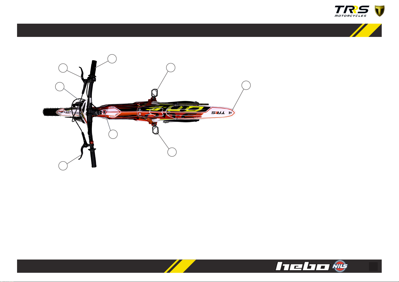
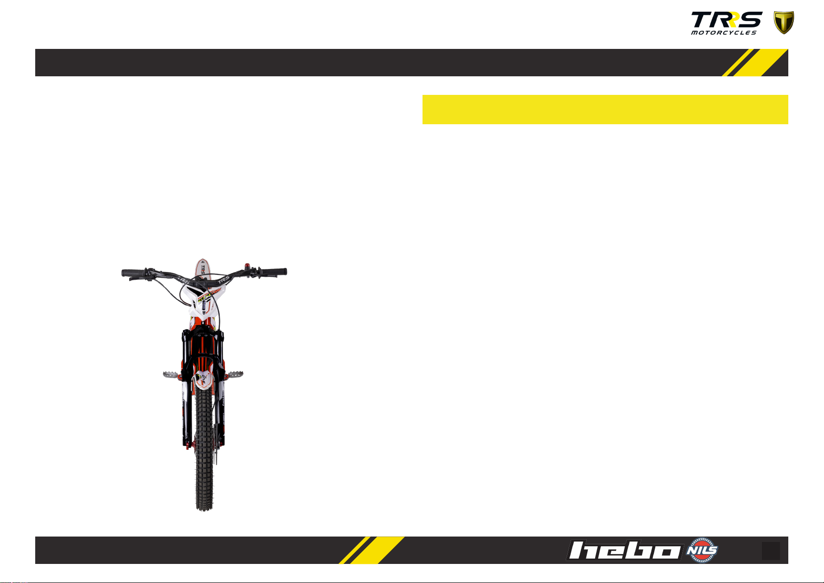
1 - DESCRIPCIÓN ELEMENTOS
01
02
03
04
05
06
07
09
10
11
12
14
13
16
15
08
01- Rear Lever brake
02- Front fork
03- Motor DC 48V
04- Shock absorber
05 - Swing arm
06- Front brake
07- Rear brake
08- Charger port
09- Front lever brake
10- Chain
11- Sprocket
12- Throle electric
13- Controller
14- Dial adjustment
15- Front fender
16- Baery
8
01
09
12
17
18
18
19
20
17- Adjustment front suspension
18- Footrests
19- Rear fender
20- LED Indicator

9
NOTA
2 - TECNICHAL SPECIFICATIONS TRS ON-E
PERFORMANCE
Maximum Speed
25 Km/h
Autonomy Unl 3h
Weight Limit Rider 35kg
CHASSIS
Frame & Swing arm
Alloy Aluminium (Red)
Front Suspension
Telescopic air fork,
26’’ adjustable rebound /
100mm stroke/ Ø32mm aluminium
Rear Shock absorber
Spring & oil type, adjustable rebound
Connecng links
Progressive system links TRRS
Front Wheel
Rebel XBIKE trial 20x2.5
Rear Wheel
Rebel XBIKE trial 20x3
Brakes
Clarks M2 Hydraulic brakes
Footrests
TRRS grip footrests. Adjustable (+/-) 2.5mm
MOTOR
1350 W 48V magnet DC motor
CONTROLLER
Adjustment controller in three terms: Power, Speed & Response.
THROTTLE
Twist type with LED baery charge indicator.
BATTERIES
CHARGER
48V lithium with capacity 17,5 Ah
Input: 100-240V - 50/60Hz 4.5A
Output: 54.6V 5A
SWITCH & DIALS AND PORTS
Switch ON /OFF
Adjustment controller: Power, Speed & Response
Kill switch
Charger port
DIMENSIONS & WEIGHT
GEARING
11T Front Sprocket / 86T Sprocket / 219 Chain
Maximum Length 160cm
Seat Height 56cm
Ground clearance 28cm
Handlebar Height 89cm
Weight 24,7 kg
Note: There are many factors eect speed and range capabilies. Terrain,
average, speed, rider weight, re pressure, wind, hills, etc.

10
3 - SAFETY RESPONSIBILITIES
Always follow the Pre-Ride Checklist before every ride.
Do not operate your ON-E if any damage is apparent. Immediately contact your local
retailer/distributor or ON-E Customer Service.
1. SUPERVISION: Riders must be supervised by responsible adults at all mes.
The rider should never be beyond eye and voice range. An adult must ALWAYS as-
sess and approve the riding condions and the bike preparedness before the bike
is ridden. Always ensure the rider is cauous, maintaining complete control and a
reasonable speed. Ensure the terrain is suited to the skills of the rider.
2. HELMETS & SAFETY ATTIRE: There is no single factor that works beer at
reducing the severity of injuries sustained in accidents more than a quality helmet.
Please don’t ever allow your ON-E to be ridden without one. Riders should also wear
suitable riding gear - gloves, eye protecon and boots. Boots should not have laces.
Shoe laces and loose clothing or even long hair could potenally get caught in whe-
els, chains or sprockets.
3. ONE RIDER ONLY: Your bike was engineered to carry one rider and no passen-
gers. Carrying a passenger would overload the machine and alter the handling. Do
not allow this to happen.
4. DON’T OVERLOAD THE BIKE: These motorcycle are designed for small, ligh-
tweight riders. Exceeding the weight limitaons will adversely aect the handling of
the machine, and potenally cause damage.
5. CONDITIONS OF USE: This motorcycle is limited to use only OFF-ROAD. This
means that this motorcycle cannot move on streets or public roads, as well as on
sidewalks. The owner of the motorcycle, is responsible for complying with this stan-
dard and others that the state where the on this type of machines resides.
6. VISIBILITY CONDITIONS: Do not ride the motorcycle, when the light condions
signicantly reduce visibility. Aenon at sunrise or sunset, even with fog or cloudy
sky. Keep in mind that this motorcycle is not equipped with posion lights.
7. ADVERSE WEATHER CONDITIONS : When the ground is wet, the adhesion of
the wheels with the ground, as well as the eecveness of the brakes, lose ecien-
cy. For this reason, it is important to know that driving should be much smoother
than in dry situaons, as the braking distance increases, as well as the danger of
skang and causing a fall. It is advised not to drive when it is raining or snowing. Take
into account these condions on at terrain and especially on steep ups and downs.
8. MAINTENANCE: Follow the maintenance of the motorcycle, it is important to
extend the life of the motorcycle, as well as ensure that the operaon is correct and
safe. Follow the instrucons in this manual. Before each use, check the operaon of
the brakes, condion of the res and ghten the related screws.
It is recommended that the motorcycle be checked by a TRS service, at least once
a year.
11
SUMMARY
9. BATTERIES: Our motorcycles are equipped with lithium-ion baeries. The loca-
on of the baery on the motorcycle protects it from possible shocks and gives it
the necessary ghtness. Review this manual to nd more specic informaon on
this aspect.
10. READ THIS MANUAL: Read completely this manual to know the characteris-
cs and partricularies of an electric motorcycle. If any doubt can not be solved with
this manual, please contact with your local TRS distributor. Your closest distributor
can be consulted on www.trsmotorcycles.com.
1. SUPERVISION: A responsible adult must supervise at all me.
2. WEAR A HELMET & SAFETY GEAR: The rider must wear a helmet & appropriate
safety gear every me.
3. NO PASSENGERS: It is totally forbidden to carry passengers.
4. DO NOT EXCEED THE WEIGHT LIMITATIONS OF THE MACHINE.
5. CONDITIONS OF USE: OFF-ROAD
6. VISIBILITY CONDITIONS
7. ADVERSE WEATHER CONDITIONS: The terrain may vary, so be responsible.
8. PLEASE MAINTAIN YOUR BIKE.
9. CARE FOR YOUR BATTERIES
10. READ, STUDY AND UNDERSTAND THIS ENTIRE MANUAL.
11. If you don’t understand any aspect of the use and care of your bike, please call TRS
costumer service.
12
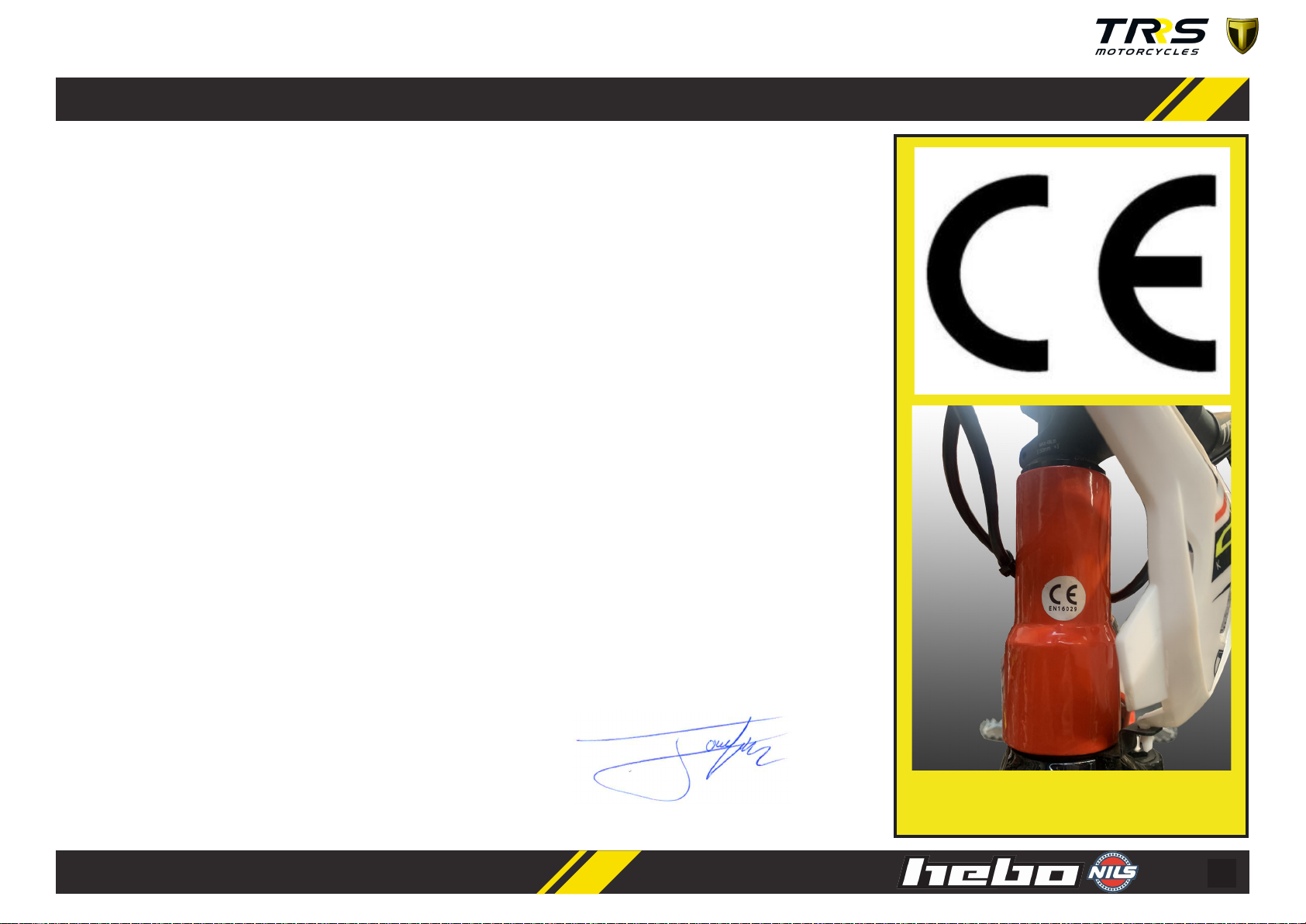
4 - CE DECLARATION OF CONFORMITY
PRODUCT DESCRIPTION: Kids Electric Motorcycle O-Road
MODEL DESIGNATION: ON-E KIDS
YEAR OF MANUFACTURE: 2020
SERIAL NUMBER : XXXXX
Comply with::
Electrical safety tests on the charger baery according EN60335-1:2008 y EN 60335-2-29:2004 (Low Voltage Di-
recve 2014/35/CE).
Safety for baeries and secondary cells IEC/EN 62133-2:2017.
EMC according to standards EN 55014-1:2017; EN 55014-2:2015; EN 61000-3-2: 2018; EN 61000-3-3:2013 +A1:
2017 (Direcve 2014/30/EU).
The following standards have been applied:
Mechanical Technical examinaon of conformity to the Machine Direcve 2006/42/EC drawn from the EN-
16029:2012 standard.
Technical documentaon led at: Signature:
TRS MOTORCYCLES, S.L.
C/ Muntaner 292 planta 3 puerta 2
08021 Barcelona (España)
Posion: Technical director Marked CE located on the head tube

13
A
5 - SERIAL NUMBER
All motorcycles that manufacture in TRS come out with an idencaon number
engraved on the frame and that appears in the technical le of the documentaon
that we deliver to the user. This number cannot be replaced or modied under
any circumstances. This number is located at the boom of the chassis, under the
engine at the rear, and may be required in any technical inspecon.
¡WARNING!
It is advisable to keep the serial number and idencaon informaon of your
motorcycle noted to expedite procedures in case of the or supply of spare parts.
SERVICE / WARRANTY
If there is a need to make a warranty claim, it must be processed by an authorized
TRS dealer. (See the Warranty page 31)
For any quesons about your ON-E, please contact a local distributor or seller.
You can check the list of distributors and contact informaon at
www.trsmotorcycles.com
A) L
ocated at the
boom of the chassis,
under the motor at
the rear
14
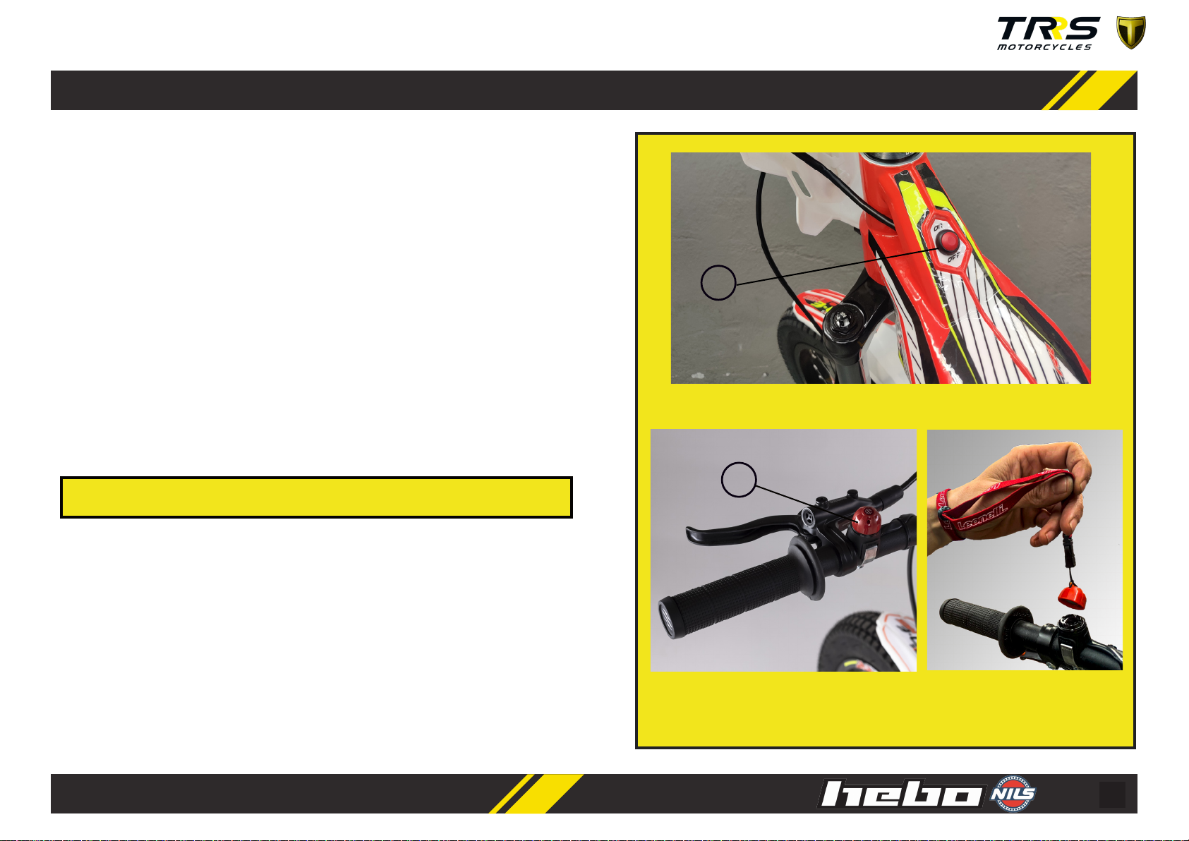
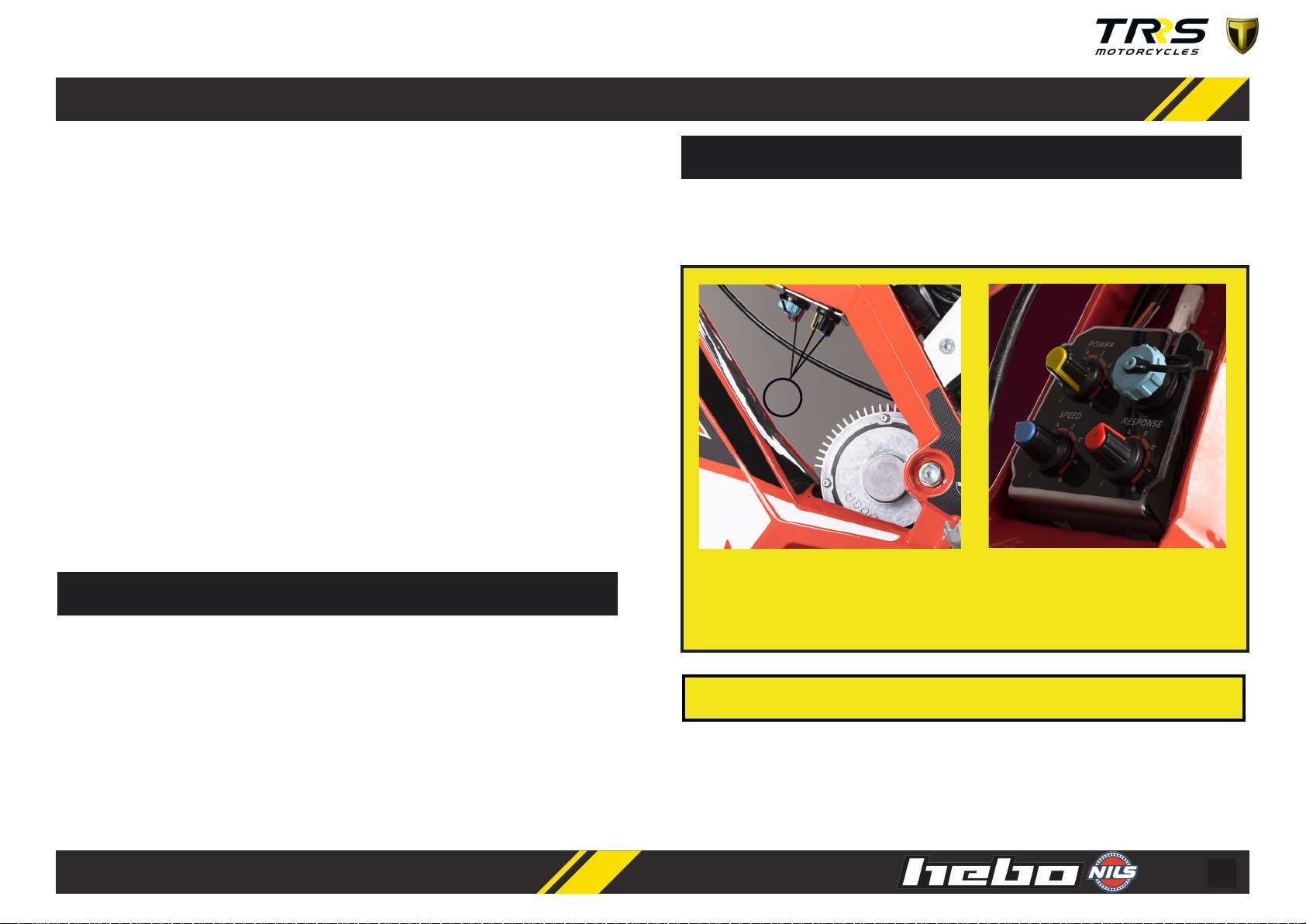
SWITCH ON/OFF
The (ON / OFF) switch allows you to turn the motorcycle on and o. The buon is
located on the chassis. Figure (A).
KILL SWITCH
This switch, is connected in series with the switch on/o. The kill switch must be in
place for the switch to be in the on posion.
It is a safety element, so that, in the event of the pilot falling, the motorcycle is
disconnected. Make sure that the rider puts the elasc band on the le wrist and is
rmly secured, before starng the motorcycle.
With this switch you can also turn the motorcycle on and o, placing the red part
on the base placed on the le side of the handlebar. It also has the funcon of an-
the or use without consent, disconnecng the red part of the base and saving it
in another place.
Figure A) Switch ON /OFF locates on the chassis
Figure B) Kill switch, put the elastic band on the left wrist
B
6 - SWITCHES, INDICATORS & DIALS
¡CAUTION!
If the accelerator is applied before connecng the kill switch, the motorcycle will
not move.
A
15
DIALS: POWER, SPEED AND RESPONSE
The motorcycle allows you to adjust the parameters to adapt the motorcycle
according to the skill of the rider, as well as the o-road condions. There are 3 dials
are located on the inside of the chassis, under the seat.
1. SPEED (Blue)
Increase or decrease top speed. For beginners, it is recommended to start with the
minimum.
2. RESPONSE (Red)
Increase or decrease the sensivity of the gas. At a minimum, the gas reacon is
slower. At maximum, the gas response is faster. For slippery surfaces and / or for
beginners, a low seng is recommended.
3. POWER (Yellow)
When the power increases, it allows geng more torque uphill and obtain faster
reacons as well as. The maximum adjustments are only recommended for more
experienced pilots.
Fig B) Dials are located inside the chassis. This allows to set: power (yellow), speed (blue) and response
(red). Turning the adjusters clockwise, the performance of the motorcycle increases. On the contrary
direction, turning counterclockwise, the performance is reduced to a minimum.
B
DIALS SHOULD BE ADJUSTED ONLY BY AN ADULT RESPONSIBLE AND KNOWLEDGE
OF THE SKILL OF THE RIDER AND OFF ROAD CONDITIONS.
It is recommended to start with all the dials to the minimum and depending on the
skills of the pilot to increase the regulaon. Take note of the found properly seng.
To become familiar with the adjustments and visualize the eect of each dial, it is
advisable to place the motorcycle on a stand and become familiar with the reacons
of the motorcycle.
PLEASE NOTE THAT:
NOTE
Prolonged use of the adjustments in the maximum posion can signicantly reduce
the autonomy compared to the adjustment in minimum posions.
¡CAUTION!
The regulators are sensive to small adjustments. Don’t guess the changes. Always
check beforehand that the sengs made are correct for the pilot’s skills.
16
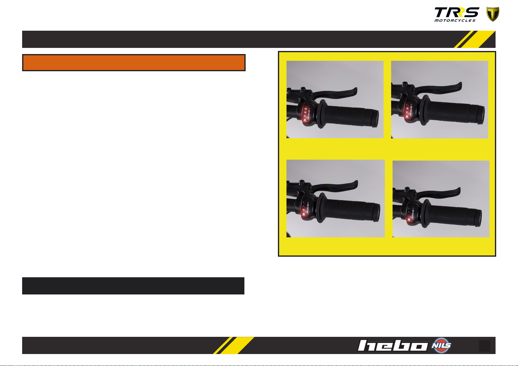
CHARGE INDICATOR
The baery charge indicator is integrated into the throle and indicates the charge
of the baery. This indicator also indicates whether the power switch is o or on.
Always turn o the switch when the motorcycle is not used.
As the baery charge depletes, the lights of the indicator will be o. When all 4
LEDs are on, it means full charge. As the load decreases, the LEDs turn o. When
only 1 led remains on, it indicates that the baery charge is low.
To extend the autonomy, it is recommended to choose posions of lower power,
speed and response as the charge decreases. When only one red LED is lit, it is
recommended to charge the ON-E as soon as possible. In this way, it is possible to
extend the life of the baery when is not consuming its charge to the maximum.
When the motorcycle do not used, the motorcycle must be disconnected, turn o
the switch.
During use, it can be seen that the indicator depletes, when the maximum power
is required, this phenomenon being normal.
It is very important to keep everyone at a distance when the motorcycle is charging
or the dials are being adjusted. Dials are sensive to small adjustments. Don’t guess
the changes. Always check beforehand that the sengs made are correct for the
pilot’s skills.
¡WARNING!
NOTE
A) Full charge of baery B) Incomplete baery charge
C) Half baery charge D) Empty baery charge
17
7 - CADENA DE TRANSMISIÓN
This motorcycle uses a chain of transmission, drive sprocket and rear sprocket
common in a motorcycle of greater size. This motorcycle has no gears, it is direct
transmission from motor to wheel.
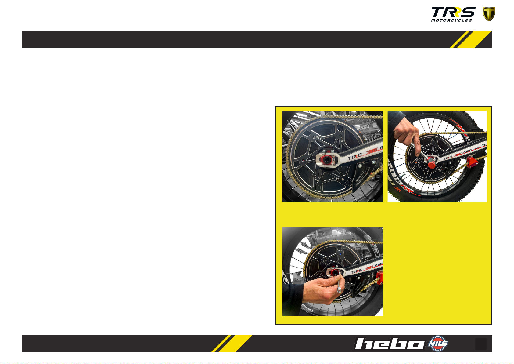
The chain must be checked before every ride and adjusted as necessary. There
should be very lile slack in the chain. Adjustment is done as follows:
1. Ensure power is turned o. Switch OFF and kill switch disconnecng.
2. Unscrew the rear wheel axle unl the wheel is free from lng. Don’t remove the
sha.
3. Chain tensioning procedure:
a) Unscrew the locknut with wrench 8mm between swingarm and wheel
tensioner. There is one on the right side and one on the le side.
b) Unscrew the screw with wrench 8mm by pushing the chain tensioner.
With lile twist, the displacement is large. Perform the operaon
symmetrically. Do not leave the chain too ght, keep in mind that when
the shock absorber is compressed, the chain tends to ghten.
c) Check that the rear wheel is aligned with the swingarm.
d) Fix the locknuts on both sides.
e) Screw the rear wheel axle.
f) Check the drive sprocket and rear sprocket screws are correctly ghtened.
g) Lubricate the chain with chain spray. TRS recommends the use of NILS
O road chain.
Unscrew the rear wheel axle with a 8mm
Allen wrench.
Unscrew the chain tensioner with a 8mm
wrench by pushing the chain tensioner.
Perform the same operaon on the other
side of the swingarm. Fix the locknuts and
screw the wheel axle. Check that the drive
sprocket and rear sprocket screws are co-
rrectly screwed.
18
B
A
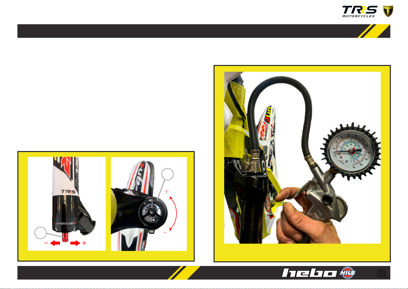
This motorcycle is equipped with pneumac suspension, front and rear adjustable.
FRONT SUSPENSION
Possible sengs are:
A) Compression: Adjustable with the knob, located on the top of the right bole.
By turning the compression dial counterclockwise we can block the damping
completely or harden it, if we turn the dial clockwise we unlock the compression.
B) Rebound:
The rebound adjuster is located on the boom of the right bole. Turning counter
clockwise we get a faster bounce, otherwise clockwise the rebound is slower.
B) Rebound A) Compression
The front suspension is an "air" fork. A specic air pump is required to
add pressure. The air pump is not supplied with the motorcycle.
We can adjust the hardness or smoothness of our suspension with an air pump.
8 - SUSPENSION
19
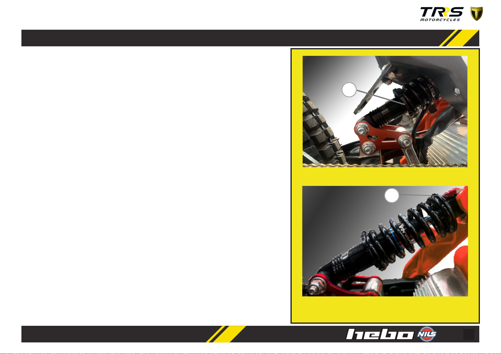
A) Spring preload
B) Rebound
B
A
8 - REAR SHOCK ABSORBER
This motorcycle is equipped with an oil damper with coil spring located at the rear.
The shock absorber is connected to a system of connecng links that confers progressively
in the travel, that is to say in the rst part of the travel the damping is so and while in the
nal part the damping hardens. This allows to increase the tracon in the rst course and
reduce the impact when the motorcycle makes a jump.
The shock absorber has the possibility of two adjustments:
A) Spring preload. By adjusng the nut that holds the spring, the force of the spring can
be hardened or soened. By turning the nut clockwise, more hardness is achieved, while
turning counterclockwise, more smoothness is achieved.
There is another replaceable spring with dierent hardness as an accessory, to get a beer
t depending on the weight and skills of the pilot.
B) Rebound. There is a knob on the top of the shock absorber. It is under the saddle.
By adjusng this parameter, the shock absorber can recover the posion aer
compression, faster or slower. In the clockwise direcon the rebound is faster, while in
the counterclockwise direcon the rebound is slower.
20
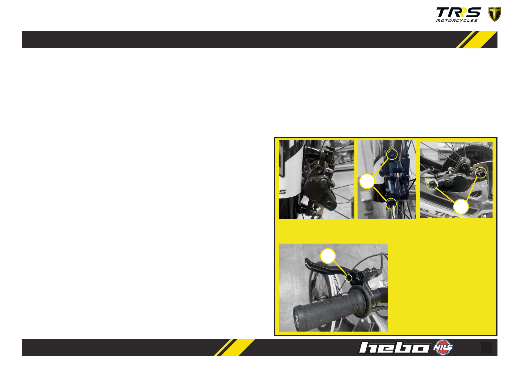
09 - BRAKES
A
B
To ensure opmal braking, it is necessary to check the condion of the brake pads:
inially they usually have 3mm of ferodo. If aer its operaon we observe that this
distance has been reduced below 2mm, it will be necessary to replace them with
new ones.
To replace, it is necessary to disassemble the front brake from the suspension
bole, removing the screw and the clip that are removed from the boom. For
assembly, it is necessary to open the pistons with a screwdriver by prying between
them to separate the pistons. In turn, you must ensure the ghtening of the screws
and pin.
The brakes are self-adjusng to a point, but their correct alignment guarantees
maximum performance. The pads should keep the same distance from the disk for
maximum eciency.
Visually inspect the pads while the wheel is spinning. Check that your alignment
is correct and keep the same distance from the disc. If you need to make any
adjustments, follow the instrucons below:
1. Remove the safety clip from the screws. There is one on each brake.
2. Using the 5mm allen wrench, loosen the two screws on the brake bracket,
allowing the caliper to move freely.
3. With the wheel raised, act on the brake lever, this will move the caliper to the
center with respect to the disc.
4. While sll acng on the brake lever, the pads rmly ghten the disc, without
releasing the lever, re-ghten the two caliper bracket screws.
5. If the wheel doesn’t turn freely aer stopping the brake, further adjustment is
A
required beyond the limits of the caliper’s own adjustment that can be achieved
using spacer washers. In this way, the clamp can align perfectly.
6. Put again the screw security clip. There is one in each clamp
7. The brake levers can be adjusted in range. Use a 2mm Allen. Turning the screw
counterclockwise manages to bring the reach closer to the handlebar (for smaller
hands)
Using the 5mm Allen wrench, loosen the two screws on the front and / or rear brake caliper.
The brake levers can be adjusted in range,
using a 2mm Allen and turning the screw
in one of the direcons we can adjust the
range we want.
Table of contents
Other TRS Motorcycle manuals


 owner's manual")


