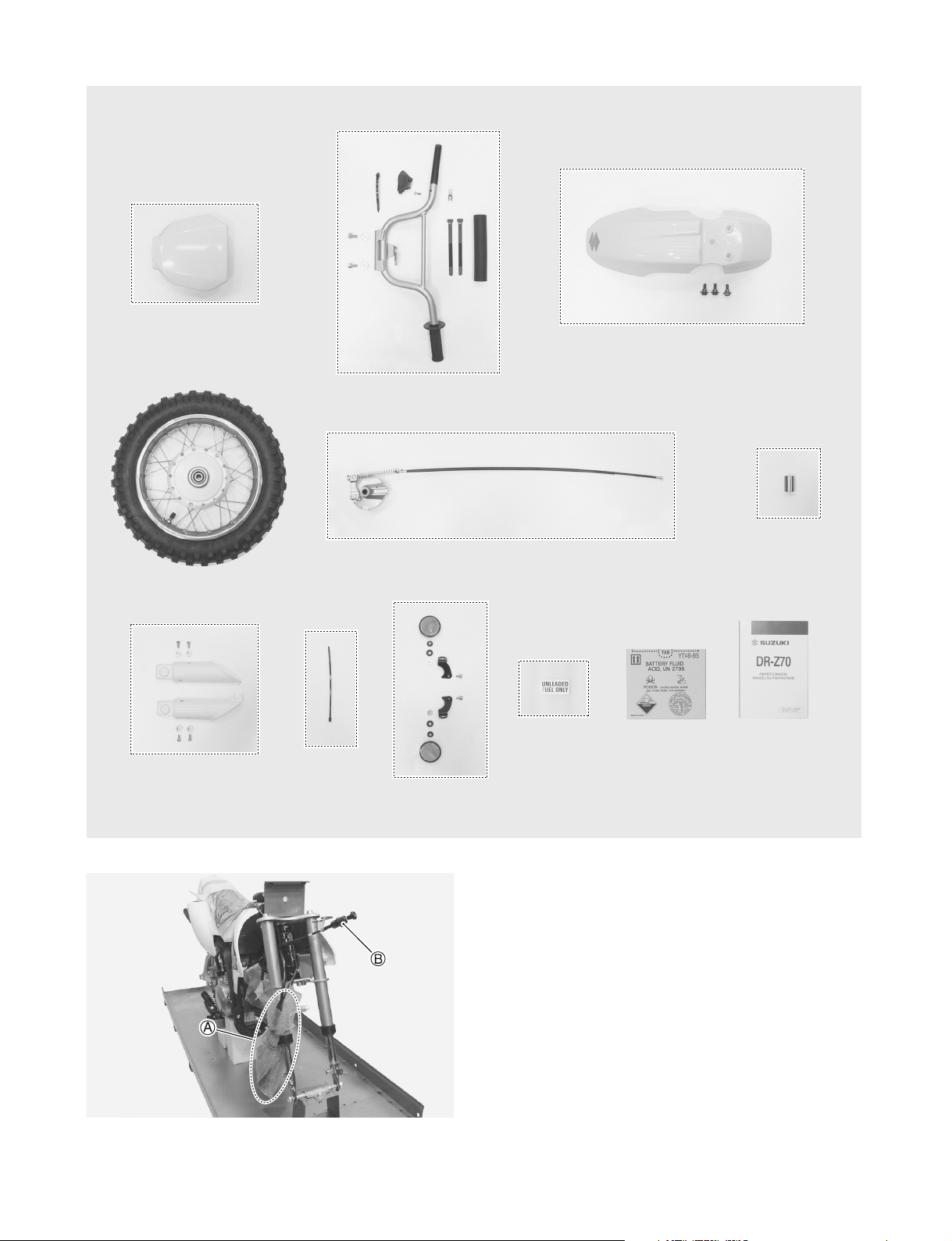
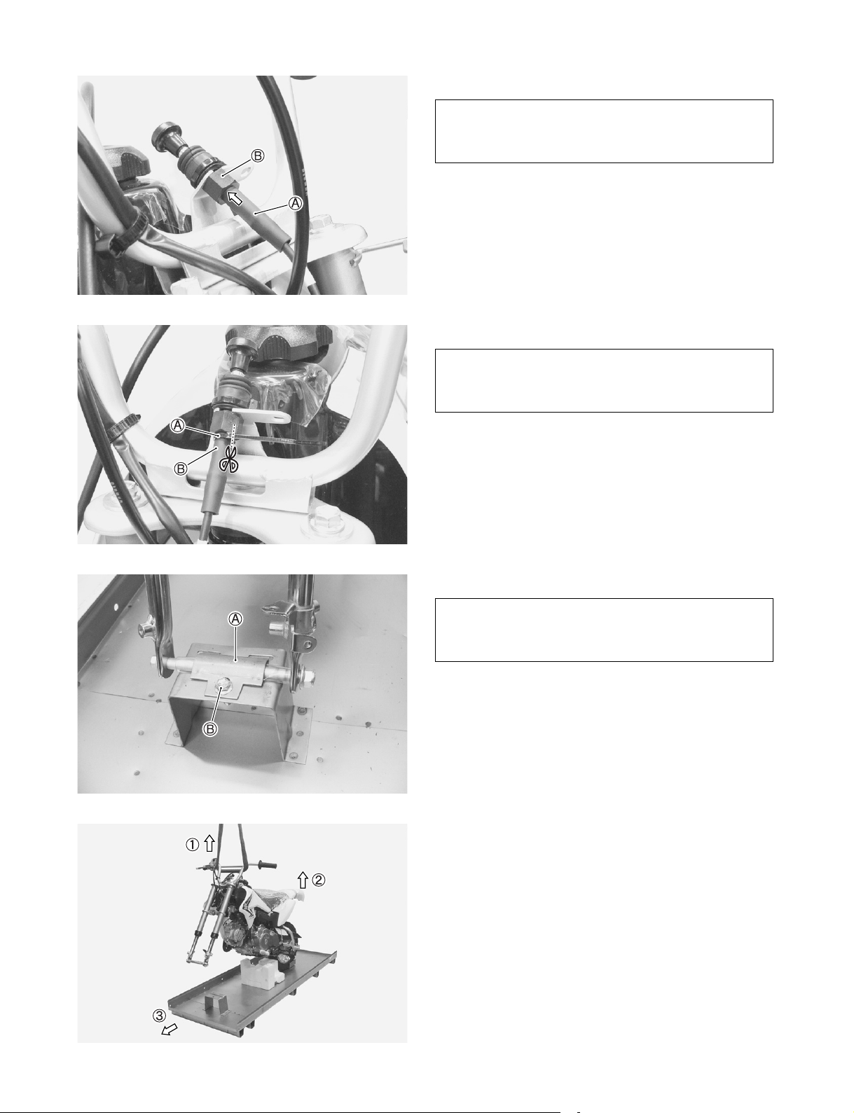
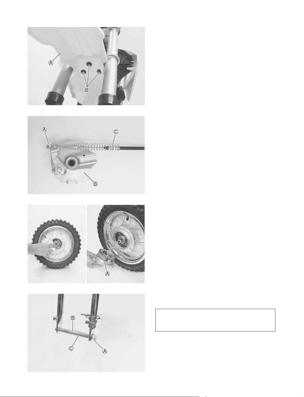
Suzuki DR-Z70K8 User guide

K8
June ’07 Printed in Japan (TK) 28
99505-01008-01E
FOREWORD
This motorcycle has been designed and produced utilizing Suzuki’s most modern
technology. The finest product, however, cannot perform properly unless it is cor-
rectly assembled and serviced. This set-up manual has been produced to aid you in
properly assembling and servicing this motorcycle.
Please review this set-up manual carefully before performing any work. Take spe-
cial care to properly perform the required assembly and servicing marked by either
a Warning or a Caution. Failure to follow the directions in either of these two (2) cat-
egories could lead to serious problems. and areas are
denoted to emphasize certain areas and carry the following meanings:
Indicates a potential hazard that could result in death or injury.
Indicates a potential hazard that could result in motorcycle damage.
This set-up manual is based on a motorcycle of standard specification. Some minor
differences from this manual may be found in other specifications.

1
PREPARATION
WORKSHOP
A: Packed motorcycle
B: Working space
SELF PROTECTION
UNCRATING THE MOTORCYCLE
Remove the carton.
A: Crate
Remove the strap.
Take out the front wheel assembly and component
parts from the crate base.
A: Strap
B: Front wheel assembly
C: Component parts
The workshop where the machine is assembled
should be clean, spacious, and have a level
floor.
The technician should wear protective clothing
such as leather gloves, a long sleeve shirt, eye
protection and safety shoes as shown in the
illustration when handling metal crates.
Metal crates may have sharp edges and may
cause injury.

2
Remove the bolts of the bracket.
Remove the bolts to take off the rear wheel holding
bracket.
A: Bolt
Remove the bolts from the crate.
A: Bolt
Lift the steel frame to separate it from the base of the
crate.
A: Steel frame
B: Crate base
Handling crates requires two operators.
Be careful not to scratch the motorcycle.

3
LOCATION OF PARTS
Check all the components which have been removed from the base of the crate.
Parts listed above are installed respectively into the positions as follows.
Item Part Name Q’ty Remarks
A Front number plate 1
B
Handlebars assembly 1
Flange bolt 2 8 × 16 mm
Washer 2 OD:22.0 ID:8.5
Screw 1 5 × 16 mm For
throttle assembly
Brake lever cover 1
Handlebar pad 1
Strap 2 L:140
Strap 1 L:100
Clip 1
CFront fender 1
Flange stepped bolt 3 6 × 18 mm
D Front wheel assembly 1
EFront brake hub panel
assembly 1
F Front wheel spacer 1
Item Part Name Q’ty Remarks
G
Front fork protector 2 Right and Left
Flange bolt 4 6 × 12 mm
Stepped washer 4 OD:16.0 ID:6.5 T:5.0
HStrap 1 L:100
For starter cable
I
Reflex reflector 2 Right and Left
Bracket 2 Right and Left
Flange bolt 2 6 × 12 mm
Collared spacer 2 OD:17.0 ID:6.5 T:7.5
Rubber grommet 2 OD:18.0 ID:8.5 T:6.0
Flange nut 2 5 mm
J Fuel label 1 For limited market
KBattery electrolyte
container 1
LOwner’smanualset 1
OD : Outside diameter (mm)
ID : Inside diameter (mm)
L : Length (mm)
T : Thickness (mm)
TL
OD ID
NOTE:
The parts shown as Item I and J in the above table are supplied for limited markets.
Please hand over the parts shown as Item L in the above table to your customer together with motor-
cycle.
GEI
DCA H B
IF
G

4
The photograph shown indicates the parts dis-
mounted from the motorcycle in addition to the items
shown in the preceding page.
A: Throttle assembly
B: Starter cable
AA
BB
CC
DD
EE
FF
GGHH
II
JJ
KKLL

5
Before assembling the motorcycle, thoroughly
understand the “Safety Check Out” described on
page 27.
After completion of assembly, carefully check the
motorcycle referring to the “Safety Check Out”,
then deliver the motorcycle to the customer.
ASSEMBLY
REMOVING THE BRACKET
Remove the bracket from the handlebar mounting
position.
A: Bracket
B: Bolt
C: Washer
D: Paper
Tighten the steering stem head bolt to the specified
torque.
Steering stem head bolt: 45 N·m (4.5 kgf-m)
A: Steering stem head bolt
B: Washer
Be careful not to scratch the fuel tank.
NOTE:
The removed bolt Band washer Care used to
tighten the steering stem.
The bracket and paper are no longer needed
and may be discarded.

6
HANDLEBARS
Loosen the throttle housing retaining screws.
Insert the throttle assembly onto the handlebars.
A: Throttle assembly
B: Handlebars
Install the handlebars to the front fork upper bracket.
Tighten the handlebar mounting bolts to the specified
torque.
Handlebar mounting bolt: 23 N·m (2.3 kgf-m)
A: Handlebar assembly
B: Front fork upper bracket
C: 8 × 16 mm flange bolt
D: Washer OD:22.0 mm ID:8.5 mm
A: Front brake cable
B: Throttle cable
C: Right switch wiring harness
The line drawings on page 25 and 26 show the
proper routing of the control cables and wir-
ings.
Refer to them in addition to following the
instructions carefully.

7
THROTTLE
Insert the boss of the throttle housing into the hole on
the handlebars.
Tighten the throttle assembly with two screws.
A: Boss
B: Hole
C: 5 × 16 mm screw
CLAMP
Clamp the right switch wiring harness and handlebar
with the strap.
A: Strap L:100 mm
B: Handlebars
C: Right switch wiring harness
STARTER CABLE
Loosen the cable lock nut.
Insert the starter cable to the starter cable bracket.
A: Starter cable
B: Cable lock nut
C: Starter cable bracket
Fit the flat surface of the starter cable and starter cable
bracket.
Tighten the cable lock nut.
A: Starter cable
B: Starter cable bracket
C: Cable lock nut
D: Flat surface
Check to ensure that the throttle operates freely
and closes automatically.

8
Place the rubber boot.
A: Rubber boot
B: Cable lock nut
Clamp the rubber boot with the strap.
A: Strap L:100 mm
B: Rubber boot
Remove the crate axle bracket from the crate base.
A: Crate axle bracket
B: Bolt
1. Lift the front of motorcycle by using a hoist.
2. Raise the rear of motorcycle.
3. Pull the crate base forward, then balance the
motorcycle.
NOTE:
Move the rubber boot until it comes to contact
with the cable lock nut.
NOTE:
Cut off the excess strap as shown in the photo-
graph.
NOTE:
The bracket and bolt are no longer needed and
may be discarded.

9
FRONT FENDER
Install the front fender to the front fork lower bracket.
A: Front fender
B: 6 × 18 mm flange stepped bolt
FRONT WHEEL
Remove the adjuster nut.
Remove the front brake cable assembly from the front
brake hub panel assembly.
A: Adjuster nut
B: Front brake hub panel assembly
C: Front brake cable assembly
Clean the brake drum with alcohol or other non-petro-
leum based solvent.
Examine the brake shoes, springs, and operating
mechanisms.
Install the brake panel into the front wheel hub.
A: Front brake hub panel assembly
Remove the front axle nut.
Remove the front axle from the fork legs.
A: Front axle nut
B: Front axle
C: Vinyl tube
NOTE:
The vinyl tube is no longer needed and this
may be discarded.

10
Mount the front wheel assembly properly.
A: Right fork leg
B: Left fork leg
C: Axle nut
D: Front wheel spacer
E: Front axle
Attach the front wheel spacer to the front wheel hub.
Place the front wheel assembly into the lower fork legs,
aligning the brake panel anchor slot onto the boss on
the left fork leg.
A: Front wheel spacer
B: Oil seal (Lip)
C: Boss
D: Anchor slot
Insert the front axle from the right side of fork leg and
fix the front wheel assembly to the front fork.
Tighten the front axle nut to the specified torque.
Front axle nut: 53 N·m (5.3 kgf-m)
A: Front axle
B: Axle nut
When attaching the front wheel spacer, be care-
ful not to scratch the oil seal lip.
Never use force to install the front axle.
If it cannot be installed by hand, it is not cor-
rectly aligned.

11
FRONT BRAKE CABLE
Pass the front brake cable through the guide.
Pass the front brake cable through the lever cover.
A: Front brake cable
B: Guide
C: Lever cover
Insert the inner cable end into the recess in the brake
lever.
Fit the outer cable into the lever holder.
Install the lever cover.
A: Front brake cable
B: Cable end
C: Lever holder
D: Brake lever
E: Lever cover
Loosen the nut.
Pass the front brake cable through the bracket.
A: Nut
B: Bracket
C: Front brake cable
Fix the front brake cable to the bracket with the nut.
Reinstall the rubber cap.
Set the front brake cable spring to the front brake
cable.
A: Front brake cable
B: Nut
C: Rubber cap
D: Front brake cable spring
NOTE:
Before installing the cable, grease cable end.
The smaller side of the front brake cable spring
should be placed below, and the bigger, above.

12
Set the pin into the brake cam lever.
Insert the end of the brake cable into the pin hole.
Attach the adjuster nut on the end of the brake cable.
Do not adjust at this time.
Adjustment will be covered in the SERVICING section.
A: Brake cam lever
B: Pin
C: Front brake cable
D: Adjuster nut
LEFT RIGHT
FRONT FORK PROTECTOR
Fit the guide to the front brake cable. (Left)
Install the front fork protector to the front fork.
A: Front fork protector
B: 6 × 12 mm flange bolt
C: Stepped washer OD:16.0 mm ID:6.5 mm T:5.0 mm
D: Left fork leg
E: Right fork leg
F: Front brake cable
G: Guide (Front fork protector)
CLIP
Clamp the throttle cable and the starter cable by using
a clip.
A: Clip
B: Throttle cable
C: Starter cable
D: White mark
FRONT NUMBER PLATE
Install the front number plate to the front fork.
A: Front number plate
B: Boss (Front fork lower bracket)
Clamp the clip in the position marked by white
mark of the starter cable.

13
HANDLEBAR PAD
Install the handlebar pad to the handlebar reinforcing
bar.
A: Handlebar pad
B: Strap L:140 mm
FUEL TANK VENT HOSE
Insert the free end of fuel tank vent hose to the hole of
starter cable bracket.
A: Fuel tank vent hose
B: Hole (Starter cable bracket)
FOOTREST
Remove the shipping pin from the footrest.
A: Footrest
B: Shipping pin
REFLEX REFLECTOR (FOR LIMITED MARKET)
Install the rubber grommet and collared spacer to the
bracket.
Set the reflex reflector using the flange nut.
A: Bracket
B: Rubber grommet OD:18.0 mm ID:8.5 mm T:6.0 mm
C: Collared spacer OD:17.0 mm ID:6.5 mm T:7.5 mm
D: Reflex reflector
E: 5 mm flange nut
FRONT
Be sure not to bend or twist the hose when
installing.
Confirm that the right and left footrests move
smoothly.

14
Install the reflex reflector assembly to the front fork
lower bracket.
A: Reflex reflector assembly
B: 6 × 12 mm flange bolt
REMOVING THE WRAP FILM
Remove the wrap film from the fuel tank cover.
A: Fuel tank cover
B: Wrap film
FUEL LABEL (FOR LIMITED MARKET)
Stick the label on the fuel tank cover.
A: Fuel tank cover
B: Fuel label
WARNING TAG
Place the warning tag to the handlebar.
A: Warning tag
NOTE:
This hangtag is not to be removed before sale.

15
SERVICING
BATTERY
The battery is located under the seat.
Remove the bolts to take off the seat.
A: Seat assembly
B: Flange stepped bolt
Remove the bolts to take off the battery holder.
Remove the battery from the motorcycle.
A: Battery holder
B: Flange bolt, Stepped washer
Filling electrolyte
Remove the aluminium tape sealing the battery elec-
trolyte filler holes.
A: Aluminium tape
B: Electrolyte filler hole
Remove the caps from the electrolyte container.
A: Caps
B: Sealed area
NOTE:
Use the removed caps as the sealed caps of
battery filler holes.
Do not remove or pierce the sealed areas of the
electrolyte container.

16
With just enough force to break the nozzle seal of elec-
trolyte container, push each nozzle of the electrolyte
container into the battery’s electrolyte filler ports and
hold the container firmly so that it does not fall.
Take precaution not to allow any of the fluid to spill.
A: Electrolyte containers
Make sure air bubbles are coming up in each electro-
lyte container, and leave in this position for about 20
minutes.
A: Air bubbles
After confirming that the electrolyte has entered the
battery completely, remove the electrolyte containers
from the battery.
Wait for around 20 minutes.
Insert the caps into the filler holes, pressing in firmly so
that the top of the each caps does not protrude above
the upper surface of the battery’s top cover.
A: Caps
NOTE:
If no air bubbles are coming up from a filler
port, tap the bottom of the container two or
three times.
Never remove the container from the battery.
Never use anything except the specified battery
electrolyte.
Once the sealing cap has been installed in the
battery, do not remove the sealing cap.

17
Charge the battery with a battery charger.
After charging the battery, install the battery in the
motorcycle as follows.
Connect the battery lead wire coupler to the battery.
Reinstall the battery in the motorcycle.
A: Battery lead wire coupler
B: Click (Coupler)
C: Boss (Frame)
D: Hole (Battery hold rubber)
E: Bracket
For charging the battery, make sure to use the
charger specially designed for MF battery.
Otherwise, the battery may be overcharged
resulting in shortened service life.
Do not remove the cap during charging.
Position the battery with the cap facing upward
during charging.
When attaching the battery lead wire coupler to
the battery terminals, observe the correct
polarity.

18
Reinstall the battery holder.
A: Battery holder
B: Flange bolt, Stepped washer
To install the seat, insert the seat hook into the seat
hook retainer.
Tighten the bolts.
A: Seat assembly
B: Seat hook
C: Seat hook retainer
D: Boss
THROTTLE CABLE
Check the throttle cable play at the throttle grip.
Throttle cable play: 2.0–4.0 mm
If adjustment is necessary, carry out the procedure
below:
1. Loosen the throttle cable adjuster lock nut A.
2. Turn the adjuster Bin or out until the correct play is
obtained.
3. Tighten the lock nut Awhile holding the adjuster B.
4. Place the rubber boot C.
After the adjustment is completed, check that
handlebar movement does not raise the engine
idle speed and that the throttle grip returns
smoothly and automatically.

19
FRONT BRAKE
Check the front brake lever play at the brake lever end
when squeezing the lever until pressure is felt.
Brake lever play: 15–25 mm
If adjustment is necessary, carry out the procedure
below.
1. Turn the front brake cable adjuster Aclockwise or
counterclockwise to obtain the specified play.
2. After adjusting the play, check that there is no drag-
ging when turning the front wheel with the wheel off
the ground.
DRIVE CHAIN
Check the drive chain slack.
Drive chain slack: 25–35 mm
If it is too tight or too loose, follow these procedures:
1. Loosen the axle nut.
2. Loosen the lock nut.
3. Adjust the slack in the drive chain by turning the
right and left chain adjuster nuts.
4. Proper chain slack is obtained when drive chain
slack is up and down, at a point midway between
the two sprockets.
5. Tighten the rear axle nut to the specified torque.
6. Tighten the adjuster nuts securely.
7. Tighten the lock nut while holding the adjuster nut.
A: Axle nut
B: Lock nut
C: Adjuster nut
D: Reference marks
Rear axle nut: 54 N·m (5.4 kgf-m)
Confirm if there is enough clearance between
the front brake lever and the throttle grip when
the front brake lever is tightly squeezed.
Make sure that the rear sprocket is properly
aligned with the engine sprocket.
Verify the reference marks on the swing-arm by
sighting down along the chain from the rear
end of the motorcycle.
25–35 mm
Table of contents
Other Suzuki Motorcycle manuals

Suzuki
Suzuki GSX250F User manual

Suzuki
Suzuki GS850G User manual

Suzuki
Suzuki Intruder VL800 User manual

Suzuki
Suzuki GZ250 Marauder User manual

Suzuki
Suzuki RM250 Application guide

Suzuki
Suzuki GS1000 User manual

Suzuki
Suzuki VZR1800/BZ User manual

Suzuki
Suzuki RM125 Application guide

Suzuki
Suzuki freewind User manual

Suzuki
Suzuki 2001 GSX-R1000 User manual

Suzuki
Suzuki drz 400E User manual

Suzuki
Suzuki GSX-R750 User manual

Suzuki
Suzuki 1980 GSX400 User manual

Suzuki
Suzuki GSF650A User manual

Suzuki
Suzuki RGV250 1989 User manual

Suzuki
Suzuki GSX600F User manual

Suzuki
Suzuki GSX R600 2003 User manual

Suzuki
Suzuki VL1500 User manual

Suzuki
Suzuki SV1000K5 Manual

Suzuki
Suzuki RF 900 R User manual