4 Manual Number 9019932 •Revision C, October 17, 2023
SECTION 1 GENERAL DESCRIPTION
1.1 INTRODUCTION
The True Blue Power TS28 series Emergency Battery Power Supply is designed to supply DC
power for aircraft loads such as lighting and other critical equipment in the event of a primary
power loss. During normal aircraft operation, the TS28 Emergency Battery Power Supply (EBPS)
will utilize aircraft power to recharge or maintain existing charge at full capacity. The TS28 is a
sophisticated power system that utilizes state-of-the-art NiMH cell technology which provides
improvements in performance, safety, and life when compared to traditional or competing backup
systems. With emphasis on a robust design, the EBPS meets applicable regulatory standards
and has been tested to environmental and performance qualifications that exceed industry
requirements. The TS28 is a complete EBPS that provides significant value and benefit to an
aircraft designer, owner and operator.
The TS28 requires professional use and maintenance to deliver maximum performance and
value as designed. This manual contains information related to the specifications, installation,
operation, storage, scheduled maintenance, and other related topics associated with the proper
care and use of this product.
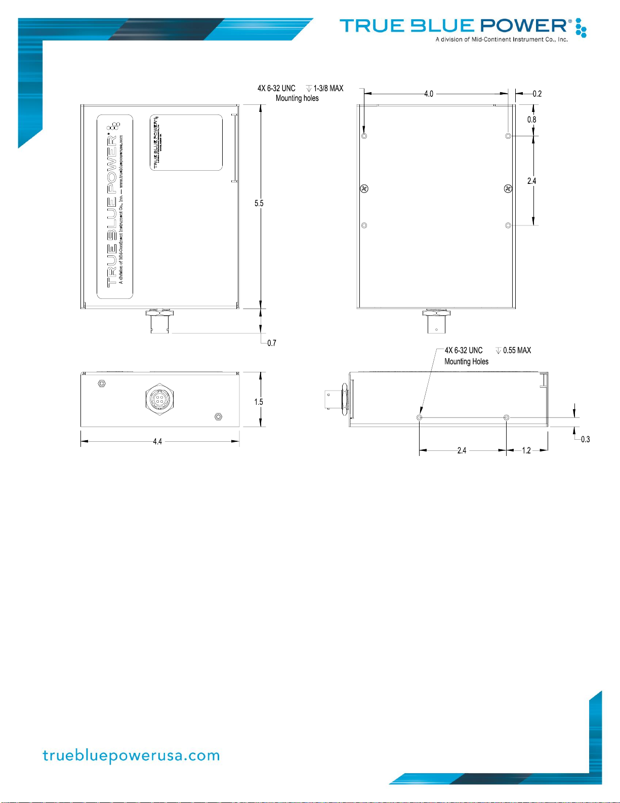
1.2 PHYSICAL ATTRIBUTES
The TS28 consists of a rugged metal chassis with a 4-pin Mil-Spec circular-style connector for
electrical interface, and a rechargeable battery that is easily removed to shorten maintenance
timelines and extend product life. The unit is designed to be mounted with four threaded
fasteners to attach the unit to the aircraft structure.
1.3 UNIT ARCHITECTURE
The unit is comprised of four primary functional pieces:
•Main Boards
•Connector Interface Board
•Battery Pack
•Metal Chassis
The external 4-pin connector used for charging, discharging and power pass-through is
connected internally to one of two main printed circuit boards (PCBs). The Main Boards provide
control of all battery functions such as management, charging and discharging. The main boards
also protect against short circuit, over temperature, under-voltage, over-voltage, and EMI
filtering.
The Battery Pack assembly contains twenty (20) cells in series, temperature sensors for
monitoring, and includes the Connector Interface Board. When installed, the connector on the
interface board plugs the battery pack into the main board. The battery pack is housed in its own
rugged metal chassis for easy handling and streamlined replacement as needed.