KEPCO BOP-H Series User manual

IMPORTANT NOTES:
1) This manual is valid for the following Model and associated serial numbers:
MODEL SERIAL NO. REV. NO.
2) A Change Page may be included at the end of the manual. All applicable changes and
revision number changes are documented with reference to the equipment serial num-
bers. Before using this Instruction Manual, check your equipment serial number to identify
your model. If in doubt, contact your nearest Kepco Representative, or the Kepco Docu-
mentation Office in New York, (718) 461-7000, requesting the correct revision for your par-
ticular model and serial number.
3) The contents of this manual are protected by copyright. Reproduction of any part can be
made only with the specific written permission of Kepco, Inc.
Data subject to change without notice.
KEPCO®
THE POWER SUPPLIER™
MODEL
OPERATOR’S MANUAL
KEPCO INC.
ORDER NO. REV. NO.
KEPCO, INC. 131-38 SANFORD AVENUE FLUSHING, NY. 11355 U.S.A. TEL (718) 461-7000 FAX (718) 767-1102
email: hq@kepcopower.com World Wide Web: ww.kepcopower.com
BOP -H SERIES
HIGH PERFORMANCE, 400W
BIPOLAR OPERATIONAL POWER SUPPLY
BOP -H SERIES
POWER SUPPLY
©2021, KEPCO, INC
P/N 243-1398


NOTE:
This manual applies to Kepco Model BOP 20-20HD, the first of a new BOP-H Series. It is equipped with
the following options:
• Option D (Display/Front Panel Control)
• Option S (Master/Slave)
Subsequent units that have these options installed will be designated as:
BOP 20-20HD04
in accordance with Table 1-1 of the manual.
KEPCO®
THE POWER SUPPLIER™
MODIFICATION OF STANDARD
KEPCO MODEL BOP 20-20HD
BOP 20-20H /042221
KEPCO, INC. 131-38 SANFORD AVENUE FLUSHING, NY. 11355 U.S.A. TEL (718) 461-7000 FAX (718) 767-1102
email: hq@kepcopower.com World Wide Web: www.kepcopower.com


BOP-H 020498 i
TABLE OF CONTENTS
SECTION PAGE
SECTION 1 - INTRODUCTION
1.1 Scope of Manual......................................................................................................................................... 1-1
1.2 Options ....................................................................................................................................................... 1-1
1.2.1 Primary Options....................................................................................................................................... 1-1
1.2.1.1 Display/Front Panel Control (D Option):............................................................................................. 1-1
1.2.1.2 Digital Remote Control (G Option, e Option)...................................................................................... 1-1
1.2.2 Secondary Options.................................................................................................................................. 1-2
1.2.3 Inductive Load Optimization (L Option):.................................................................................................. 1-2
1.2.4 Capacitive Load Optimization (C Option):............................................................................................... 1-2
1.2.5 Inductive Load Optimization (LC Option): ............................................................................................... 1-2
1.2.6 Master/Slave (S Option):......................................................................................................................... 1-2
1.2.7 Relay - Crowbar (R Option):.................................................................................................................... 1-2
1.2.8 DC Current Transformer (DCCT) (Z Option):.......................................................................................... 1-3
1.3 General Description.................................................................................................................................... 1-3
1.4 Electrical Specifications, General............................................................................................................... 1-4
1.5 Miscellaneous Features.............................................................................................................................. 1-12
1.5.1 Output Range.......................................................................................................................................... 1-12
1.5.2 Programming Features............................................................................................................................ 1-12
1.5.3 ON-OFF Feature..................................................................................................................................... 1-13
1.5.4 Load Reactance...................................................................................................................................... 1-13
1.5.4.1 Driving an Inductive Load in Current Mode........................................................................................ 1-13
1.5.4.2 Driving a Capacitive Load in Voltage Mode ....................................................................................... 1-14
1.5.5 Remote Turn-off...................................................................................................................................... 1-14
1.5.6 Circuit Breaker Shutdown Prevention ..................................................................................................... 1-15
1.5.7 References.............................................................................................................................................. 1-15
1.5.8 Series Or Parallel Operation ................................................................................................................... 1-15
1.5.9 Voltage Control Channel......................................................................................................................... 1-15
1.5.10 External Voltage Monitor......................................................................................................................... 1-16
1.5.11 External Current Monitor......................................................................................................................... 1-16
1.5.12 Mode Control........................................................................................................................................... 1-17
1.5.13 Current Control Channel ......................................................................................................................... 1-17
1.5.14 Bounding................................................................................................................................................. 1-17
1.5.15 Front Panel Status Indications ................................................................................................................ 1-18
1.5.15.1 POWER (G)/FAULT (R)/LIMIT (O) indicator...................................................................................... 1-18
1.5.15.2 OUTPUT ON indicator ....................................................................................................................... 1-18
1.5.15.3 MASTER (G)/SLAVE (Y) indicator..................................................................................................... 1-18
1.5.15.4 DIG ON/REM ON-OFF indicator........................................................................................................ 1-18
1.5.16 Rear Panel Status Indications................................................................................................................. 1-19
1.5.17 Standards................................................................................................................................................ 1-19
1.6 Mechanical Specifications .......................................................................................................................... 1-19
1.7 Equipment Supplied.................................................................................................................................... 1-19
1.8 Accessories ................................................................................................................................................ 1-20
1.9 Safety.......................................................................................................................................................... 1-21
SECTION 2 - INSTALLATION
2.1 Unpacking and Inspection. ......................................................................................................................... 2-1
2.2 Terminations, Controls and Indicators........................................................................................................ 2-1
2.3 Factory Defaults.......................................................................................................................................... 2-13
2.4 A-C Input Requirements ............................................................................................................................. 2-13
2.5 Cooling........................................................................................................................................................ 2-13
2.6 Preliminary Checkout.................................................................................................................................. 2-13
2.7 Installation................................................................................................................................................... 2-19
2.7.1 Slide Installation...................................................................................................................................... 2-19
2.8 Load Connection......................................................................................................................................... 2-21
2.8.1 Load Connection, Local Sensing............................................................................................................. 2-21
2.8.2 Load Connection, Remote Sensing......................................................................................................... 2-21

ii BOP-H 042221
TABLE OF CONTENTS
SECTION PAGE
2.8.3 A-C Ground............................................................................................................................................. 2-21
2.8.4 D-C Ground ............................................................................................................................................ 2-22
2.9 Cooling....................................................................................................................................................... 2-23
2.10 Setting up the unit...................................................................................................................................... 2-24
2.10.1 Setup for Analog Control ........................................................................................................................ 2-24
2.11 Multiple Unit Configurations (S Option Required)...................................................................................... 2-25
SECTION 3 - OPERATION
3.1 Introduction ................................................................................................................................................ 3-1
3.2 Power Supply Basics ................................................................................................................................. 3-1
3.2.1 Safety Precautions.................................................................................................................................. 3-1
3.2.2 Active Programming Sources................................................................................................................. 3-2
3.2.3 External Leads........................................................................................................................................ 3-2
3.3 Power Supply Operation............................................................................................................................ 3-2
3.3.1 Turning the Power Supply On................................................................................................................. 3-2
3.3.2 Simplified Application and Test Setup Requirements............................................................................. 3-3
3.3.3 Setting Operating Mode (Voltage or Current)......................................................................................... 3-3
3.3.4 External Voltage Monitor........................................................................................................................ 3-3
3.3.5 External Current Monitor......................................................................................................................... 3-3
3.3.6 Setting Current Limits............................................................................................................................. 3-4
3.3.6.1 Setting Current Limits with D Option installed................................................................................... 3-4
3.3.6.2 Setting Current Limits Without D Option............................................................................................ 3-4
3.3.7 Setting Voltage Limits............................................................................................................................. 3-5
3.3.7.1 Setting Voltage Limits with D Option installed................................................................................... 3-5
3.3.7.2 Setting Voltage Limits Without D Option ........................................................................................... 3-6
3.3.8 Voltage Mode Operation with Current Limiting....................................................................................... 3-6
3.3.9 Current Mode Operation with Voltage Limiting....................................................................................... 3-8
3.3.10 Using the BOP as a Voltage Amplifier.................................................................................................... 3-9
3.3.11 Using the BOP as a Current Amplifier.................................................................................................... 3-10
3.3.12 BOP CONTROLLED BY AN EXTERNAL RESISTANCE....................................................................... 3-10
3.4 Series/Parallel Master/Slave Connections................................................................................................. 3-10
SECTION 4 - CALIBRATION
4.1 Introduction ................................................................................................................................................ 4-1
4.2 Test Equipment Requirements .................................................................................................................. 4-2
4.3 Internal Adjustments and Calibrations ....................................................................................................... 4-3
4.3.1 Buffer Zero (A1A1R3)............................................................................................................................. 4-3
4.3.2 Preamplifier Zero (A1A1R33) ................................................................................................................. 4-4
4.3.3 Voltage Monitor and Feedback Zero (A1A2R12).................................................................................... 4-4
4.3.4 Output Voltage Zero Adjustment (A1A1R112)....................................................................................... 4-5
4.3.5 Output Current Sensing Zero Adjustment (A1A1R18)............................................................................ 4-5
4.3.6 Output Current Zero Adjustment (A1A1R113)........................................................................................ 4-5
4.3.7 Output Current Full Scale Calibration (A1A1R72).................................................................................. 4-6
4.4 S Option Calibrations and Adjustments ..................................................................................................... 4-6
4.4.1 Parallel Slave Output Current Reference Zero (A5R24)......................................................................... 4-7
4.4.2 Parallel Slave Output Current Zero (A5R17).......................................................................................... 4-7
4.4.3 Series Slave Output Voltage Zero (A5R28)............................................................................................ 4-8
SECTION 5 - S OPTION - SERIES/PARALLEL MASTER/SLAVE
5.1 Introduction ................................................................................................................................................ 5-1
5.2 Multiple Unit Configurations (S Option Required)...................................................................................... 5-1
5.2.1 Configuring Multiple Units - General Rules............................................................................................. 5-1
5.3 Parallel Master/Slave configurations.......................................................................................................... 5-2
5.3.1 Master Initial Settings (Parallel).............................................................................................................. 5-2
5.3.2 Slave Initial Settings (Parallel)................................................................................................................ 5-3
5.3.3 Local Sensing Connections (Parallel)..................................................................................................... 5-4

BOP-H 020498 iii
TABLE OF CONTENTS
SECTION PAGE
5.3.4 Remote Sensing Connections (Parallel) ................................................................................................. 5-6
5.3.5 Parallel Configuration Operation............................................................................................................. 5-6
5.4 Series Master Slave configurations ............................................................................................................ 5-8
5.4.1 Initial Master Settings (Series) ................................................................................................................ 5-8
5.4.2 Initial Slave Settings (Series) .................................................................................................................. 5-9
5.4.3 Local Sensing Connections (Series)....................................................................................................... 5-10
5.4.4 Remote Sensing Connections (Series)................................................................................................... 5-12
5.4.5 Series Configuration Operation............................................................................................................... 5-12
5.5 Total Output Voltage and Current of for Multiple Units............................................................................... 5-14
5.6 Multiple Unit Fault Response/Recovery...................................................................................................... 5-14
5.7 S Option Calibration.................................................................................................................................... 5-15

LIST OF FIGURES
FIGURE TITLE PAGE
iv BOP-H 042221
1-2 BOP Output Characteristic......................................................................................................................... 1-12
1-3 BOP Output WaveForms with Phase Shift................................................................................................. 1-13
1-4 How to Change Preamplifier Gain.............................................................................................................. 1-16
1-5 Boundaries and Limits................................................................................................................................ 1-18
1-6 Mechanical Outline Drawing, BOP-H......................................................................................................... 2-23
2-1 BOP Terminations and Controls, Front Panel............................................................................................ 2-1
2-2 BOP Terminations and Controls, Rear Panel............................................................................................. 2-4
2-3 BOP Control/Access Terminal Block.......................................................................................................... 2-8
2-4 BOP EXTL CTRL Port................................................................................................................................ 2-10
2-5 BOP EXTL FLAG Port................................................................................................................................ 2-11
2-6 BOP ANALOG Port.................................................................................................................................... 2-12
2-7 Rear Panel Default Settings, Microswitches and Jumpers......................................................................... 2-13
2-8 Test Setup for Voltage Mode Using Rear Panel Input and Control............................................................ 2-15
2-9 Test Setup for Current Mode Using Rear Panel Input and Control............................................................ 2-17
2-10 Slide Installation on Full-rack Units............................................................................................................ 2-20
2-11 Load Connection Using Local Sensing at Rear Panel, Output Floating..................................................... 2-22
2-12 Load Connection Using Remote Sensing at BOP Rear Panel................................................................... 2-23
3-1 Graphs Of Possible Input/output Waveshapes .......................................................................................... 3-9
4-1 Locations of Calibration Adjustments and Test Points, Top View, Cover Removed.................................. 4-2
5-1 Parallel Configuration, Local Sensing, Typical........................................................................................... 5-5
5-2 Parallel Configuration, Remote Sensing, Typical....................................................................................... 5-7
5-3 Series Configuration, Local Sensing, Typical............................................................................................. 5-11
5-4 Series Configuration, Remote Sensing, Typical......................................................................................... 5-13

BOP SERIES 020498 v
LIST OF TABLES
TABLE TITLE PAGE
1-1 Additional Option(s) Installed ......................................................................................................................1-2
1-2 General Specifications ................................................................................................................................1-4
1-3 Output Ranges, Transfer Factor and Output Impedance ............................................................................1-11
1-4 Equipment Supplied ....................................................................................................................................1-19
1-5 Accessories - Not Supplied .........................................................................................................................1-20
1-6 Safety Symbols ...........................................................................................................................................1-21
2-1 BOP Front Panel Terminations and Controls ..............................................................................................2-1
2-2 BOP Rear Panel Terminations and Controls ..............................................................................................2-4
2-3 BOP Control/Access Terminal Block ...........................................................................................................2-9
2-4 BOP EXTL CTRL Port Pin Assignments .....................................................................................................2-10
2-5 BOP EXTL FlAG Port Pin Assignments ......................................................................................................2-11
2-6 BOP ANALOG Port Pin Assignments .........................................................................................................2-12
2-7 Chassis Slide Mounting Holes ....................................................................................................................2-19
4-1 Internal Adjustments and Calibrations ........................................................................................................4-1
4-2 Suggested Sense Resistors ........................................................................................................................4-3

vi BOP-H 042221
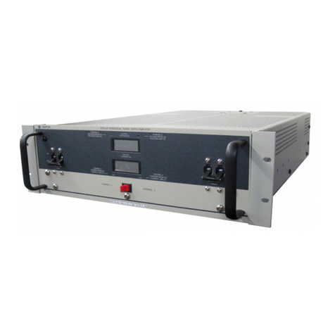
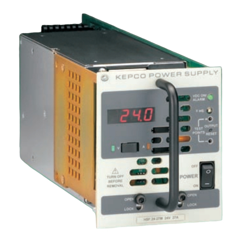
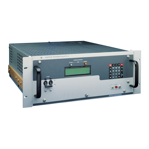
FIGURE 1-1. BOP 20-20H 400W POWER SUPPLY, D OPTION
(DISPLAY/FRONT PANEL CONTROL) INSTALLED)
3044328

BOP-H 042221 1-1
SECTION 1 - INTRODUCTION
1.1 SCOPE OF MANUAL
This manual contains instructions for the installation and operation of the BOP-H Series of 400
Watt High Performance bipolar operational power supplies, hereafter referred to as BOP-H or
simply BOP, manufactured by Kepco, Inc., Flushing, New York, U.S.A.
1.2 OPTIONS
The BOP-H configuration is defined by options indicated by a suffix following the H of the model
comprised of letters which define the primary options installed, and in some cases, numbers
which define any secondary options installed.. Primary options are defined by letters D, G and E
and are explained in PAR. 1.2.1 below. Secondary options are explained in PAR. 1.2.2. Consult
factory for the BOP-H models and options available.
1.2.1 PRIMARY OPTIONS
The primary options define the method of controlling the unit.
There are three primary options indicated by a letter suffix following the H:
• D Option (Front panel display/control)
• G Option (Digital remote control via GPIB and RS 232 )
• E Option (Digital remote control via LAN/Ethernet and USB)
More than one primary option can be installed, but only one digital interface can be selected.
The following combinations are possible
• H: Rear panel analog control input only, w/o front panel display/control and w/o digital
control
• HD: front panel control, no remote digital control
• HG: with GPIB/ RS232 digital control, w/o front panel display/control
• HE: with LAN digital control, w/o front panel display/control
• HDG: with both front panel display/control and GPIB/RS232 digital control
• HDE: with both front panel display/control and LAN digital control
1.2.1.1 DISPLAY/FRONT PANEL CONTROL (D OPTION):
D Option models allow front panel control of the BOP-H. This option includes two digital meters
on the front panel used to display output DC voltage and output DC current. Also included are
an OUTPUT ON switch that allows output on-off control from the front panel, DC bias pot and
BIAS ON switch that allows on-off control of DC bias from the front panel and an INPUT twinax
BNC jack for remote control of the main channel.
1.2.1.2 DIGITAL REMOTE CONTROL (G OPTION, E OPTION)
G or E Option models include a factory installed digital interface card that allows digital remote
control. Digital remote control for G Option models is via GPIB or RS 232 protocols using SCPI
commands. Digital remote control for E Option models is via either an ethernet/LAN interface
using a web browser, an RS 232 interface, or via a USB digital interface. Both digital options
include a local digital bus (IEEE 1118, Bitbus) used for communication between units connected
in series or parallel (see Option S, PAR. 1.2.6).

1-2 BOP-H 042221
1.2.2 SECONDARY OPTIONS
There are six secondary options which are defined in the following paragraphs. Table 1-1 lists
the combinations of secondary options as defined by a numerical suffix.
1.2.3 INDUCTIVE LOAD OPTIMIZATION (L OPTION): L Option models are stable handling heavy
inductive loads (factory tests were performed with loads up to 1 Henry). The L Option can be
enabled/disabled by a microswitch on the rear panel.
1.2.4 CAPACITIVE LOAD OPTIMIZATION (C OPTION): C Option models are stable handling
capacitive loads (factory tests were performed with loads up to 10mF). The C Option can be
enabled/disabled by a microswitch on the rear panel.
1.2.5 INDUCTIVE LOAD OPTIMIZATION (LC OPTION): LC Option models include both L Option
(see PAR. 1.2.3) and C Option (see PAR. 1.2.4). The L/C Option can be enabled/disabled by a
rear panel microswitch. Once enabled, a rear panel microswitch allows selection of either L
Option or C Option.
1.2.6 MASTER/SLAVE (S OPTION): S Option models have the ability to be connected in series or
parallel with identical BOP models for increased voltage or current, respectively. Multiple units
can be connected in a master/slave configuration to provide a single integrated output where
control of the master controls the series/parallel system. Universal cable kits can be used for
connecting both series and parallel configurations; the only differences between kits are the
number of cables included, corresponding to the number of BOP units to be configured.
1.2.7 RELAY - CROWBAR (R OPTION): R Option consists of an internal normally-closed relay or
contactor that is in parallel with the BOP output. The relay is open during normal operation, and
closes upon a) input power loss, b) internal fault, or c) external shutdown. This option is useful
when driving inductive loads by shorting the BOP output, allowing the load’s stored energy to
TABLE 1-1. ADDITIONAL OPTION(S) INSTALLED
Suffix Options installed
LCLCSRZ
01 YES
02 YES
03 YES
04 YES
05 YES
06 YES YES
07 YES YES
08 YES YES
09 YES YES
10 YES YES
11 YES YES
12 YES YES
13 YES YES YES
14 YES YES YES
15 YES YES YES
16 YES YES YES YES

BOP-H 042221 1-3
dissipate when one of the conditions mentioned above occurs.. This option is only available
when L Option is installed.
1.2.8 DC CURRENT TRANSFORMER (DCCT) (Z OPTION): Z Option models use a DCCT current
transformer as an output current transducer. The use of output current feedback and monitoring
of the DCCT device permits higher performance accuracy and stability when the unit is operated
in current mode when compared to the resistive shunt included in models without the Z Option.
1.3 GENERAL DESCRIPTION.
Kepco Series BOP H Bipolar Power Supplies are linear stabilizers for laboratory and systems
applications, able to operate in all four voltage-current quadrants, and able to pass smoothly
through the zero point. The BOP is an all solid-state design, featuring IC operational amplifiers
in the control circuit section and silicon power transistors mounted on fan-cooled heat sinks in
the complementary power stage.
The BOP has two bipolar control channels (voltage or current mode), selectable and individually
controllable either a) from the front panel controls and a remote signal applied to the INPUT
connector on the front panel if D Option is installed, or b) by remote signals applied to the Ana-
log Port at the rear panel. The BOP output is protected by bipolar limit circuits. The positive and
negative current or voltage limit points can be manually set or remotely programmed simultane-
ously or individually. The BOP features automatic crossover with a rectangular characteristic
between each principal control channel and its associated limit channels.
All control and limit channels are connected to the complementary output stage via an EXCLU-
SIVE OR gate, so that only one channel, main or limit, is in control of the BOP output at any one
time. The BOP output can be programmed over its full output range in both voltage mode and
current mode by an external ±10 volt signal. This signal can be applied to either a) the front
panel INPUT connector (if D option is installed) or b) the rear panel Analog Port. The limit con-
trol loops/channels can be controlled locally through the rear panel trimpots and through analog
remote signals applied to the rear panel Analog Port.. The lower value (either local or remote)
will be active.
If a digital remote card is installed (G or E Option models), and the BOP output is being con-
trolled digitally, it can only control the main channel and its complementary limit channel, with
identical values for positive and negative limits. The lower limit value between the remote Ana-
log Port, rear panel trimpots, and the digital setting will be active. The output value programmed
digitally for the main channel (voltage in voltage mode, current in current mode) will be summed
with either a) the programming signal from the Analog Port or b) the programming signal from
the front panel INPUT jack and/or the internal DC Bias if D Option installed.

1-4 BOP-H 042221
1.4 ELECTRICAL SPECIFICATIONS, GENERAL
See Table 1-2 for general specifications
TABLE 1-2. GENERAL SPECIFICATIONS
SPECIFICATION RATING/DESCRIPTION CONDITION/COMMENT
Input Voltage (Nominal) 115/ 230Vrms Range: ±9%
Rear panel selection
Input Brown-out Voltage 104Vrms @ 115V/60Hz, Sourcing nominal output
power
Input Frequency (Nominal) 50/ 60Hz Range:± 3Hz
Input Current 9.1Arms @ 115V/60Hz, Sourcing nominal output
power
Input Power (Active) 870W @ 115V/60Hz, Sourcing nominal output
power
Power Factor 0.8 @ 115V/60Hz, Sourcing nominal output
power
Efficiency 45% @ 115V/60Hz, Sourcing nominal output
power
Input Leakage Current 50uArms @ 115V/ 60Hz, Sourcing nominal output
power
Insulation Coordination • Installation Cat. 2
• Over-voltage Cat. 2
• Pollution Degree 2
Maximum 420V DC or Peak between
each output terminal and chassis-
ground.
Type Of Stabilizer Voltage-Current, 4-quadrant
Topology Linear, Half Bridge Class AB
OutputVoltage Voltage Mode 0 to ±EOnom V (DC or peak) See Table 1-3 for EOnom values.
Current Mode 0 to ± (1.04)(EOnom) V (DC or peak)
OutputCurrent Voltage Mode 0 to ± (1.04)(IOnom) A (DC or peak) See Table 1-3 for IOnom values.
Current Mode 0 to ± IOnom A (DC or peak)
Output Power
(Nominal) Source Mode 400 Watts (DC or peak) See Table 1-3 for DC for source mode
power values.
Sink Mode 200 Watts (DC or peak) Dissipative sink of 400W for short term
operation. Limited automatically to
200W after a critical heatsink temp. is
reached. See Table 1-3 for DC for sink
mode power values.

BOP-H 042221 1-5
Voltage, Analog Programming
(Voltage mode) Default values, for 10V programming
signal: Change the gain/transfer factor
by attaching resistors at the rear panel
Control/Access terminal block using a
screwdriver for a range of 0.1 to 10 (with
1.0 the default value) times nominal
preamp transfer factor value. See Table
2-3, items 5 through 8 for details. Default
Gain is +2A/V or -2A/V for BOP 20-
20HD
Gain/DC Transfer
Factor +EOnom/10V/V or -EOnom/10V/V, using
a rear panel micro-switch
Accuracy 0.05% of rated output
DC Bias (-1.005)EOnom to (+1.005)EOnom D Option only.
Voltage Static
Specifications
(Voltage mode)
Source effect 0.001% of rated output Input voltage = nominal ±9%
Load effect 0.002% of rated output No load to (1.05 x EOmax)/IOmax
Time effect (8h) 0.002% of rated output After 30 minutes of conditioning
Temp. coefficient 0.001% of rated output/ °C Averaged for the operating temperature
range.
Ripple & noise (rms) 0.002% of rated output
Current, Analog Programming
(Current mode) Default values, for 10V programming
signal. Change the gain/transfer factor
by attaching resistors on the rear euro-
block using a screwdriver for a range of
0.1 to 10 (with 1.0 the default value)
times nominal preamp transfer factor
value. See Table 2-3, items 5 through 8
for details.+2A/V or -2A/V for BOP 20-
20HD
Gain/DC Transfer
Factor +IOnom/10A/V or -IOnom/10A/V, using a
rear panel micro-switch
Accuracy 0.05% of rated output
DC Bias (-1.005)IOnom to (+1.005)IOnom D Option only.
Current Static
Specifications
(Current mode)
Source effect 0.001% of rated output
Load effect 0.002% of rated output
Time effect (8h) 0.005% of rated output
Temp. coefficient 0.002% of rated output/ °C
Ripple & noise (rms) 0.008% of rated output
TABLE 1-2. GENERAL SPECIFICATIONS (CONTINUED)
SPECIFICATION RATING/DESCRIPTION CONDITION/COMMENT

1-6 BOP-H 042221
Analog Programming Input
Type Differential The output can be controlled by the sum
of analog and digital controls. See
Tables 2-1 and 2-6 for details.
Max Voltage ±10V (differential), ±15V to signal ground/
COM S
Impedance 50k Ohms (differential),
500k Ohms (to signal ground/COM S
Location Twinax BNC on front panel for D Option
(Display) or use the Analog Port (rear
panel 15pin D-type connector)
Output ON-OFF (Enable-Disable) Control Rear panel isolated on/off controlling
signal A rear microswitch establishes which
control is active: front- for D Option
(Display) only or rear. The DIGITAL ON
(G) REM ON-OFF (Y) front panel light
shows which control is active. See
Tables 2-1, 2-2 and 2-4 for details.
D Option (Display) In addition to basic unit control, the unit
has two switches for DC bias on/off and
overall output on/off
G or E Options (Digital
remote control) On/off using a remote digital command; if
digital interface is in control, local and
analog control is disabled.
Voltage Mode/Current Mode Controls • Using rear panel microswitch.
• Using a rear panel remote isolated
signal.
• Using a digital command (for an
optional digital card installed and
active). If in control, the digital interface
disables the local or analog control.
A rear micro-switch establishes whether
local or analog- remote control is
enabled. The front panel VOLTAGE (G)
CURRENT (Y) indicator lights green or
yellow to show the actual mode of
operation. See Tables 2-1, 2-2 and 2-4
for details.
Digital Programming Optional Digital card Installed inside the
unit. G Option for either GPIB or RS 232
control, or E Option for either LAN, RS
232 or USB control.
Able to control the mode of operation,
output on-off status, the output voltage
and current and to monitor DC output
voltage and current.
Calibration Trimpots for analog control (see Section4
for details.).
Digital calibration for G or E option.
Voltage - Dynamic Specs (Voltage Mode)
3-dB Bandwidth 50kHz Sine with full scale input amplitude,
Nominal Resistive Load
Rise-fall time (10-90%) 7s ±full scale input, Nominal Resistive Load
Slew rate (max) 4.5V/s ±full scale input, Nominal Resistive Load
Current Dynamic Specs (Current mode)
3-dB Bandwidth 38kHz Sine with full scale input amplitude,
Short-circuit
Rise-fall time (10-90%) 9s ±full scale input, Short-circuit
Slew rate (max) 3.5A/s ±full scale input, Short-circuit
TABLE 1-2. GENERAL SPECIFICATIONS (CONTINUED)
SPECIFICATION RATING/DESCRIPTION CONDITION/COMMENT

BOP-H 042221 1-7
Special Dynamic Configurations
Preamplifier bandwidth
reduction 16kHz bandwidth, using rear panel
switch, mode independent (see Table 2-2
for details).
To reduce total unit’s bandwidth in
voltage mode or current mode, attach
external capacitor to corresponding
terminals of Control/Access terminal
block (see Table 2-3) using a
screwdriver.
Main loop bandwidth
reduction Possible for both voltage and current by
adding compensation at rear euro-block.
L, C, LC Options Rear panel microswitches able to set or
disable L, C and L/C Options. With L/C
enabled, rear panel microswitch allows
selection of either L or C Option.
The unit can be populated for any option
combinations (see Table 1-1).
Voltage/Current Limits (Pos & Neg)
Local/ rear panel
adjustment. range 0.2% to 104% of rated output Lowest of local and remote analog and
digital limit value is active. Ten turns
trimpot control for each limit +EOlim,
-EOlim, +IOlim, -IOlim; Full scale
tolerance: 1%
Analog-remote
adjustment range 2% to 100.2% of rated output For 0V to +10V controlling voltage,
Accuracy: 0.1% for voltage and 0.2% for
current
Digital-remote
adjustment range 0.2% to 100.1% of rated output Accuracy: 0.05% for voltage and 0.1%
for current
Analog Readback For Voltage and Current For 0 to ±Nominal output voltage and
current.
Range 0 to ±10V
Accuracy 0.1% of Full Scale
Max current 4mA Available at the Analog Port (see Table
2-6 for details.
TABLE 1-2. GENERAL SPECIFICATIONS (CONTINUED)
SPECIFICATION RATING/DESCRIPTION CONDITION/COMMENT

1-8 BOP-H 042221
Reference Voltages The reference voltages are available for
external usage (for limits for example) at
the rear Analog Port (see Table 2-6 for
details)
Value +10V, -10V
Tolerance ±5mV
Load Current 4mA max.
Source Effect 0.0005%
Load Effect 0.0005%
Time Effect 0.005%
Temperature
Coefficient 0.005%/°c
Kelvin Connection
(remote error sensing) Possible, with max 0.25V/ wire Sensing terminal are available at rear
Terminal Block (see Table 2-3 for details)
Local Output Monitoring Type D Option (Display) only: Digital Panel
Meters for output voltage and current. Digital Panel Meter w. pos-green
backlight. Able to display DC and signals
with less than 0.1Hz frequency.
Accuracy Digital Panel Meter: ± (0.2% of rating + 1-
count) typical
Front Panel Lights (See Figure 2-1 and
Table 2-1 for details) POWER (G), FAULT (R) or LIMIT (O) Lit green when power on. Lit red when
fault. Lit orange when in current or
voltage limit mode.
V MODE (G) or C MODE (Y) Lit green when in Voltage Mode. Lit
yellow when in Current Mode
OUTPUT ON Lit green when output is ON (enabled)
and it is not lit when the output is OFF
(disabled)
MASTER (G) or SLAVE (Y) Lit green for master. Lit yellow for slave
DIG ON (G) or REM ON-OFF (Y) Lit green when digital interface is active.
Lit yellow when output on-off is via
remote signal applied to rear panel
EXTL CTRL Port.
Flag Signals On-off Isolated signals (see Table 2-5 for
details).
Fault
Voltage-Current Mode
Limit
Front panel
controls and
inputs (see
Figure 2-1 for
details)
All options Input Circuit Breaker Dual pole, magnetic circuit breaker with
current trip coil for input overcurrent
D Option installed • Digital output voltage (VOLTS) and
current (AMPS) LCD meters
• DC bias-on switch
• DC bias adj. pot with mechanical read-
out
• Output on-off switch
• Input Twinax BNC jack
TABLE 1-2. GENERAL SPECIFICATIONS (CONTINUED)
SPECIFICATION RATING/DESCRIPTION CONDITION/COMMENT

BOP-H 042221 1-9
Rear panel
controls and
inputs
All Options • AC inlet
•ACselector
• Output power terminals/busbars
• Euro-block with: monitoring, sensing,
grounding network, grounding,
reducing bandwidth, changing gain/DC
transfer factor terminals
• Analog I/O port (analog remote input
for main channel and 4-limits, output
voltage and current monitoring signals,
±10V references
• (4) Limit trimpots
• Fault reset push-button
• Setting microswitches (voltage-current
mode, remote-local for mode control,
front-rear for on/off, invert-noninvert
configuration, regular-reduced (low)
preamplifier bandwidth, yes-no for CB
tripping at power loss, yes-no for CB
tripping at failure
• External control port, w. isolated
signals (on-off, shut-down, reset,
voltage-current mode, inter-lock shut-
down if internally set to enable)
• External flag port, w. isolated signals
(on-off, fault, voltage-current mode,
limit)
See Figure 2-2 and Table 2-2 for details.
L, C, LC Options Two switches allow selection of
• L option installed: Reg (standard) or L
• C option installed: Reg (standard) or C
• LC optioninstalled: Reg (standard) or L
or C
See Figure 2-2 and Table 2-2 for details.
S Option
(Master-Slave) • Control and Protection port IN
• Control and Protection port OUT
• Master-slave setting micro-switches
(alone-multiple, series-parallel, master-
slave)
• Slave address microswitches
See Figure 2-2 and Table 2-2 for details.
G Option • GPIB port
• RS232 port
• BitBus port
• Trigger port
See Figure 2-2 and Table 2-2 for details.
E Option • LAN port
•USBport
• BitBus port
• Trigger port
• LAN reset switch
• LAN indicators
See Figure 2-2 and Table 2-2 for details.
TABLE 1-2. GENERAL SPECIFICATIONS (CONTINUED)
SPECIFICATION RATING/DESCRIPTION CONDITION/COMMENT

1-10 BOP-H 042221
Series or
Parallel
configurations
(of identical
units)
Type of connection Master-Slave
Implementation The cable KIT is universal, independent
of model or series/parallel configuration,
without any changes to the units. The
cable KIT is number-of-units dependent.
Each unit, master and all slaves, must
have the S-option installed (factory pre-
calibrated)
Max units in series Max 3 units
Max units in parallel Max 5 units
Protections (a) Input over-current
(b) Wrong AC input (230V for 115V
setting)
(c) Heat sink overtemperature
(d) Heat sink cooling air overtemperature
(e) Fan not running
(f) Output sensing error
(g) Interlock
(h) Multiple units interlock
(i) Input power loss
(j) Output crowbar contactor (optional)
• (a), (b) trips input circuit breaker.
• (c) through (h) faults the unit. A rear
panel switch can be set up to either
trip or not trip (default) the input circuit
breaker. A fault sets the output to OFF,
set the limits to zero and activates a
temporary output crowbar (for
standard and L option only).
• (c to f) are indicated by corresponding
LEDs on rear panel
• (i) A rear panel switch can be set to
either trip or not trip the input circuit
breaker upon input power loss. The
default position is to trip at power loss.
• (j ) Protects the load and the BOP
against an inductive load's
overvoltage generated upon BOP
power loss or failure.
Temperature Operating 0 to +50° C Full power to 40°C, Derate output power
10W per °C above 40°C.
Storage -20 to +85° C
Humidity 0 to 95% RH
Shock 20g/11ms/50% half sine Non-operating
Vibration 5-10Hz 10mm, double amplitude Non-operating
10-55Hz 2g
Altitude Sea level to 10,000ft For operating temperature range
Cooling Type 2-DC Fans Zero clearance between stacked units.
Air Flow Front to rear
Air Intake front and sides
Dimensions 5.25” H x 19” W x 18.75” D
(133.4mm H x 482.6.3mm W x
476.25mm D)
Weight BOP 100W, 200W (6) 60 lbs (27.2 kg) Unpacked
TABLE 1-2. GENERAL SPECIFICATIONS (CONTINUED)
SPECIFICATION RATING/DESCRIPTION CONDITION/COMMENT
Table of contents
Other KEPCO Power Supply manuals

KEPCO
KEPCO JBW 05-3R0 User manual

KEPCO
KEPCO MSK 10-I0M User manual

KEPCO
KEPCO BOP-MG User manual

KEPCO
KEPCO HSF 3.3-30-1UR User manual

KEPCO
KEPCO EFX 100-T User manual

KEPCO
KEPCO RAX 3.3-10K User manual

KEPCO
KEPCO FPD 100W-48V User manual

KEPCO
KEPCO BOP 400W User manual

KEPCO
KEPCO HSP 1000W User manual

KEPCO
KEPCO 3.3-70K User manual

KEPCO
KEPCO KLP 10-150-(2) User manual

KEPCO
KEPCO HSF 12-53W User manual

KEPCO
KEPCO FPD 50W-24V User manual

KEPCO
KEPCO JQE Series User manual

KEPCO
KEPCO ATE 1/4 RACK User manual

KEPCO
KEPCO BOP 500DM User manual

KEPCO
KEPCO MAT Series User manual

KEPCO
KEPCO ATE 6-25 User manual

KEPCO
KEPCO JQE 25-20MVPY-27274 User manual

KEPCO
KEPCO FPD 50W-12V User manual