TSA Systems BM-185D Operation manual

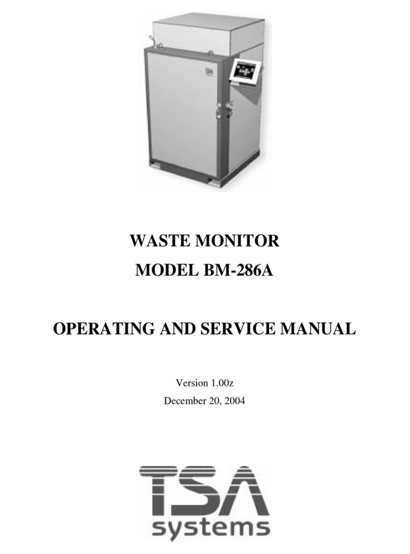
BAG/BOX MONITORS
MODEL BM-185D/285D/286D
OPERATION AND SERVICE MANUAL
Doc. #5016 Rev. A
August, 2006

Doc. # 5016 BM-185D/285D/286D Rev. A
Operation an Service Manual
How to use this manual
Configuration tracking sheet: Recor of system configuration, mo ifications, upgra es, etc.
Stan ar Warranty
Table of Contents
Section 1: Provi es a general escription an specifications for the unit.
Section 2: Inspection an installation (if require ) instructions.
Section 3: General operating an programming instructions.
Section 4: Har ware theory of operation.
Section 5: Calibration an perio ic maintenance instructions.
Section 6: Troubleshooting gui e an iagnostic tools.
Glossary: Definition of terms
Appen ix A: List of mathematical formulas that are use in TSA systems.
Parts Lists: Detaile parts lists by subassembly inclu ing the manufacturer's
part numbers an instructions for or ering spare parts.
Drawings: Drawings an schematic iagrams for the system.

Doc. # 5016 BM-185D/285D/286D Rev. A
Operation an Service Manual
CONFIGURATION TRACKING SHEET
TSA MODEL NUMBER:______________ SERIAL NUMBER:_________________________
SOFTWARE VERSION:______________ DATE RECEIVED:_________________________
OPTIONS AND ACCESSORIES:__________________________________________________
_____________________________________________________________________________
SYSTEM MODIFICATIONS
MODIFICATION:_____________________________________________________________
____________________________________________________________________________
INSTALLED BY:_________________________________________ DATE:__________
MODIFICATION:_____________________________________________________________
____________________________________________________________________________
INSTALLED BY:_________________________________________ DATE:__________
MODIFICATION:_____________________________________________________________
____________________________________________________________________________
INSTALLED BY:_________________________________________ DATE:__________
MODIFICATION:_____________________________________________________________
____________________________________________________________________________
INSTALLED BY:_________________________________________ DATE:__________

Doc. # 5016 BM-185D/285D/286D Rev. A
Operation an Service Manual
STANDARD WARRANTY FOR TSA SYSTEMS INSTRUMENTS
TSA Systems, Lt . warrants this instrument to be free from efects in workmanship an
materials for a perio of twelve months from the ate of shipment, provi e that the equipment
has been use in a proper manner an not subjecte to abuse. At TSA's option, repairs or
replacements will be ma e on in-warranty instruments without charge at the TSA factory.
Warranty of sub-systems ma e by other manufacturers will be exten e to TSA customers only
to the extent of the manufacturer's liability to TSA. TSA reserves the right to mo ify the esign
of its pro uct without incurring responsibility for mo ification of previously manufacture units.
Since installation con itions are beyon the company's control, TSA oes not assume any risks
or liabilities associate with metho s of installation or with installation results.
Every effort is ma e to keep the manuals up to ate an accurate. However, because TSA
Systems is constantly improving an upgra ing the pro uct line, TSA can make no guarantee as
to the content of current manuals. No obligations are assume for notice of change or future
manufacture of these instruments.
Manufactured by
TSA S stems, Ltd.
14000 Mead Street
Longmont, Colorado USA 80504-9698
Phone: +1.970.535.9949
FAX: +1.970.535.3285

Doc. # 5016 BM-185D/285D/286D Rev. A
Operation an Service Manual
TABLE OF CONTENTS
1.0 INTRODUCTION........................................................................................................ 1
1.1 Scope an Purpose of Manual................................................................................1
1.2 General Description................................................................................................1
1.3 BM-285D/286D Specifications..............................................................................2
2.0 INSPECTION AND INSTALLATION.......................................................................3
2.1 Inspection...............................................................................................................3
2.1.1 Incoming Inspection......................................................................................3
2.1.2 Damage Claims.............................................................................................3
2.1.3 Storage...........................................................................................................3
2.1.4 Shipping.........................................................................................................3
2.2 Installation..............................................................................................................3
3.0 OPERATING INSTRUCTIONS.................................................................................4
3.1 General Overview...................................................................................................4
3.2 Power-Up an Self-Tests........................................................................................5
3.2.1 Detector Detail..............................................................................................7
3.2.2 Tare Scale......................................................................................................8
3.2.3 Recor Backgroun .......................................................................................8
3.2.4 Up ate Backgroun .......................................................................................8
3.2.5 Operator Log On...........................................................................................8
3.2.6 User Log Off.................................................................................................8
3.2.7 View MCA Scan...........................................................................................8
3.2.8 Set-up.............................................................................................................8
3.2.9 Utilities..........................................................................................................8
3.2.9 Set-up Waste Streams....................................................................................9
3.3 Normal Operation.................................................................................................10

Doc. # 5016 BM-185D/285D/286D Rev. A
Operation an Service Manual
3.4 Programming the System.....................................................................................15
3.4.1 Set-Up Menu...............................................................................................16
3.4.1.1 Backgroun Time............................................................................17
3.4.1.2 Backgroun Metho ........................................................................17
3.4.1.3 Low Fault........................................................................................17
3.4.1.4 High Fault........................................................................................17
3.4.1.5 Variance Time.................................................................................17
3.4.1.6 Variance Trials................................................................................17
3.4.1.7 Units of Weight...............................................................................17
3.4.1.8 Minimum Weight............................................................................17
3.4.1.9 Reports.............................................................................................18
3.4.1.10 Report Type...................................................................................18
3.4.1.11 Label Printing................................................................................18
3.4.1.12 BM I entification..........................................................................18
3.4.1.13 User Waste Stream........................................................................18
3.4.1.14 Units..............................................................................................18
3.4.1.15 Force Backgroun .........................................................................18
3.4.1.16 Notify User if SCALE Drifts.........................................................19
3.4.1.17 TARE Scale Type..........................................................................19
3.4.1.18 Intermec Printer Support...............................................................19
3.4.1.19 Notify User if SCALE Drifts.........................................................19
3.4.1.20 Prompt for Waste Item ID Before a Scan......................................19
3.4.1.21 Enable Scale Auto-TARE An Drift Alerts..................................19
3.4.1.22 Enable Two Energy Win ows on Waste Streams.........................19
3.4.1.23 Disable Scale Controller an SPACT Alarm Logic......................19
3.4.1.24 Use MDA Calculator for Dynamic Alarm Levels.........................19
3.4.1.25 Print Sample Data button..............................................................20
3.4.2 Set-Up Waste Streams.................................................................................20
3.4.2.1 Name of Waste Stream....................................................................21
3.4.2.2 Count Time......................................................................................22
3.4.2.3 Count Display..................................................................................22
3.4.2.4 MCA Data.......................................................................................22
3.4.2.5 Alarm Message................................................................................22
3.4.2.6 Clean Message.................................................................................22
3.4.2.7 Alarm Type......................................................................................23
3.4.2.8 Efficiency........................................................................................23
3.4.2.9 Alarm Level.....................................................................................23
3.4.2.10 False Alarm Rate...........................................................................24
3.4.2.11 Confi ence Level..........................................................................24
3.4.2.12 Maximum Weight..........................................................................24
3.4.3 Set Discriminators.......................................................................................25

Doc. # 5016 BM-185D/285D/286D Rev. A
Operation an Service Manual
3.4.4 Variance.......................................................................................................26
3.4.5 Efficiency Check.........................................................................................27
3.5 Diagnostics an Utilities......................................................................................29
3.5.1 Operator Setup.............................................................................................29
3.5.2 Calibrate Electronics...................................................................................30
3.5.2.1 Calibration To Do List....................................................................30
3.5.2.2 Event Log........................................................................................30
3.5.2.3 Detector Information.......................................................................30
3.6 Reports..................................................................................................................31
3.7 Set-Up Checklist...................................................................................................32
3.8 BM-185D/285D/286D Waste Stream Set-Up Worksheet....................................33
4.0 THEORY OF OPERATION......................................................................................34
4.1 General Overview.................................................................................................34
4.2 Components..........................................................................................................34
4.2.1 Component Locations..................................................................................34
4.2.2 Computer an Power Supply.......................................................................35
4.2.3 Low Voltage Power Supply........................................................................35
5.0 MAINTENANCE........................................................................................................36
5.1 Operator Maintenance..........................................................................................36
5.2 Calibration............................................................................................................36
5.3 Discriminator A justment....................................................................................37
5.4 Weight Calibration...............................................................................................37
5.5 MCA Calibration (optional).................................................................................37
5.6 Calibration Checklist............................................................................................38
6.0 TROUBLESHOOTING.............................................................................................39
6.1 Diagnostic Tools...................................................................................................39
6.1.1 Variance.......................................................................................................39
6.1.2 Efficiency Check.........................................................................................39
6.1.3 Com Port Setup...........................................................................................40
6.2 Fault Isolation.......................................................................................................41
6.3 Computer..............................................................................................................41
6.4 Signal Interface Assembly an Detectors............................................................41
6.5 Loa Cell Central Calibration..............................................................................42
GLOSSARY......................................................................................................................43
APPENDIX A....................................................................................................................44
Spare Parts Or ering Information......................................................................................47
List of Drawings................................................................................................................. 49

Doc. # 5016 BM-185D/285D/286D Rev. A
Operation an Service Manual

Doc. # 5016 BM-185D/285D/286D Rev. A
Operation an Service Manual
1.0 INTRODUCTION
1.1 SCOPE AND PURPOSE OF MANUAL
This manual is esigne to enable operating an service personnel to properly operate an care
for the BM-185D/285D/286D. Since applications are necessarily site-specific, operation
proce ures are given in general terms. Service an repair are covere to the boar level.
1.2 GENERAL DESCRIPTION
TSA's Barrel Monitor, Mo el BM-185D/285D/286D, is a large barrel monitoring evice,
esigne to screen bulky items of up to 1,000 poun s (454kg) for ra ioactive contamination. It
uses six plastic scintillation etectors, one on each si e of the chamber. An optional so ium
io i e scintillation etector can be provi e for spectral monitoring.
Operation of the instrument is controlle from a touch screen LCD monitor or optionally using
an external computer keyboar . All access is controlle by user-assigne passwor protection. A
printer can be connecte for report printing or the printing of container ata labels.
The instrument performs a self-test an acquires a new backgroun count each time it is powere
up. It also monitors its own operation uring normal use an in icates any failures. It runs
continuously, up ating backgroun s whenever no weight is etecte insi e the chamber. A new
count is initiate every time a oor open/ oor close sequence is etecte .
The BM-185D/285D/286D isplays the total activity, scale to appropriate units (µCi, nCi, etc.)
an specific activity in pCi/gram or nCi/gram. These units are also inclu e in reports an ata
sample information that are create by the unit.
The unit operates on 100-240Vac, 50-60Hz power with circuit breaker protection.
PAGE 9

Doc. # 5016 BM-185D/285D/286D Rev. A
Operation an Service Manual
1.3 BM-285D/286D SPECIFICATIONS
Input Power: 100-240Vac, 50-60 Hz, 6A
Detectors 285: Two 12" x 19" x 1.5" (30.5cm x 48.2cm x 3.8cm) plus four 12" x
25" x 1.5" (30.5cm x 63.5cm x 3.8cm) plastic scintillation etectors
couple to photo-multiplier tubes via light pipes.
Detectors 286: Two 12" x 24" x 1.5" (30.5cm x 60.9cm x 3.8cm) plus four 12" x
35" x 1.5" (30.5cm x 88.9cm x 3.8cm) plastic scintillation etectors
couple to photo-multiplier tubes via light pipes. Total etector volume is
3,384 in3 (55 liters)
Optional Detector: One 3" x 3" NaI(Tl)
Sensitivity: See Acceptance Data
Scan Time: 1 to 50,000 secon s, user-programmable
Backgroun Time: 20 to 10,000 secon s, user-programmable
Sample Weight 285: 5 to 500lb (2.3 to 230kg)
Sample Weight 286: 5 to 1,000lb (2.3 to 455kg)
Serviceability: May be repaire to the boar /subassembly level in the fiel
Unit Weight 285: 10,000lb (4,545kg) with 1 3/4" lea shiel ing
Unit Weight 286: 12,000lb (5,455kg) with 1 3/4" lea shiel ing
Dimensions 285: 61" high x 40" wi e x 44" eep (154.9cm x 101.6cm x 110cm)
Dimensions 286: 74" high x 44" wi e x 45" eep (188cm x 110cm x 114.3cm)
Internal Cavity 285: 31" high x 24" wi e x 27" eep (78.7cm x 60.9cm x 68.5cm)
Internal Cavity 286: 44" high x 28" wi e x 28" eep (110cm x 70cm x 70cm)
Temperature Range: Operating: 32 to 100°F (0 to 40°C)
Storage: 0 to 120° F
PAGE 10

Doc. # 5016 BM-185D/285D/286D Rev. A
Operation an Service Manual
2.0 INSPECTION AND INSTALLATION
2.1 INSPECTION
2.1.1 Incoming Inspection
Imme iately inspect the system for mechanical amage, scratches, ents, or other efects. It
shoul be examine for evi ence of conceale amage, as well as external isfigurement.
2.1.2 Damage Claims
If the system is amage in transit or fails to meet specifications upon receipt, notify the carrier
an TSA Systems imme iately. Shipping cartons, packing materials, waybills, an other such
ocumentation shoul be preserve for the carrier's inspection. TSA will assist in provi ing
repair or replacement of the system as necessary.
2.1.3 Sto age
Care shoul always be taken to avoi subjecting the system to severe mechanical or electrical
shock. The system shoul be store in a ry location an in a temperature range of 0 to 50°C.
2.1.4 Shipping
Before returning the system for any reason, notify TSA Systems of the ifficulty encountere .
Please be prepare to give the mo el an serial numbers of the equipment. TSA will furnish
precise shipping instructions.
2.2 INSTALLATION
The system is complete an rea y to operate when it is shippe . The tablet PC, store insi e the
chamber, must be mounte to the system. Mount the PC with the screws provi e on the right
si e an connect the following cables.
System AC
Speaker
PC AC
SC-770 Controller RS-485
The power cor locate on the right of the unit plugs into a stan ar 100-240 volt, 47-63 Hz ac
receptacle provi e on the controller enclosure. When the system is installe at its operating
location, perform the set-up escribe in section 3.1. General Overview shoul be performe .
PAGE 11

Doc. # 5016 BM-185D/285D/286D Rev. A
Operation an Service Manual
3.0 OPERATING INSTRUCTIONS
3.1 GENERAL OVERVIEW
When the BM-185D/285D/286D is initially installe at its operating location, the operating
parameters must be a juste to meet the local con itions an testing requirements. Most of the
a justments are accesse via the software set-up mo e.
A touch screen keyboar will appear any time you are require to enter ata into the system.
Use of the provi e stylus will help in accessing buttons an entering information.
A "Set-Up Checklist an a Waste Stream Programming Worksheet" can be foun at the en of
this section. The Set-Up Checklist shoul be uplicate an fille in for each test source that will
be use with the system. A copy of the complete form shoul be kept in a convenient location
as a reference for i entifying future problems. The Waste Stream Programming Worksheet
contains entries for each of the operating parameters in the in ivi ual waste streams. The system
permits up to 20 pre-programme waste streams, an the form may be copie as require to
assist in programming these waste streams.
The set-up mo e is passwor protecte , with two levels of user access provi e . Both level 0 an
level 1 operators have access to the normal operation of the BM-185D/285D/286D. Operators
with level 0 (a ministrative) access may change operating parameters an change iscriminator
settings.
Determining the operating parameters is largely epen ent on local requirements an con itions.
PAGE 12

Doc. # 5016 BM-185D/285D/286D Rev. A
Operation an Service Manual
3.2 POWER-UP AND SELF-TESTS
The main power switch is locate on the right si e of the BM-185D/285D/286D.
When the system is turne on the computer performs a Power-On Self-Test (POST) which
checks an initializes the system har ware. At the en of this test, an au ible 'beep' is soun e . If
the beep fails to soun uring start-up, there may be a problem with au ible alarms uring
sample testing.
The operating system (Win ows 2000) is then loa e from the har isk. The program can be
run from the esktop shortcut, or irectly from its location on the HDD. If the system fails to
power up correctly, try turning the power switch on the si e of the controller mo ule off for a
few secon s an then back on to re-initiate the tests.
Once the computer has successfully complete its tests an the program is executing, the system
will isplay the normal backgroun collection screen. The etector win ows shoul be gray, an
a pop-up win ow isplaying the message "GETTING nn SECOND BACKGROUND" will
appear. The chronograph will show the remaining time of the count.
As soon as the backgroun count is complete (the time is etermine by the current entry in the
Set-Up Menu), the operator must log-on before any operations can be preforme . A scale tare is
recommen e at this time. After the scale tare is complete, the blue "READY" win ow will
light, an the current backgroun in counts per secon will be isplaye in black text on a blue
backgroun . The etector win ows are positione graphically to in icate which etectors they
represent. If a backgroun fault con ition (either high or low) is etecte the etector win ows
will be isplaye in black text on a magenta backgroun . The errant etectors will isplay either
"**HI**" or "**LO**". The fault con ition must be correcte before operation will be allowe .
PAGE 13

Doc. # 5016 BM-185D/285D/286D Rev. A
Operation an Service Manual
A menu is isplaye across the bottom of the screen. The available functions are:
Level One Access
Detector Detail
TARE Scale
Recor Backgroun
Up ate Backgroun
Operator Log-On
Operator Log-Off
PAGE 14

Doc. # 5016 BM-185D/285D/286D Rev. A
Operation an Service Manual
Level Zero Access (password protected)
View MCA Scan
Setup Menu
Utilities
Setup Waste Streams
3.2.1 Detecto Detail
After a scan of an item in the chamber, this screen shown below will give the user the initial
backgroun for the scan as well as the Net CPS, the Gross CPS, the Net Scan, or the Gross Scan
epen ing on which is selecte in the Setup Waste Streams menu.
PAGE 15

Doc. # 5016 BM-185D/285D/286D Rev. A
Operation an Service Manual
3.2.2 Ta e Scale
Prompts the operator to verify that the chamber is empty an press the OK button to tare the
scale.
3.2.3 Reco d Backg ound
For future use
3.2.4 Update Backg ound
This button is use to force a backgroun up ate of the system.
3.2.5 Ope ato Log On
Is use to log a new user onto the system. A user must be logge on to the system before any
samples are teste . The new user will be prompte for both name an ba ge number. Logging on
a new user automatically logs off the existing user.
For initial setup use: User name - TIM, Ba ge - 11, Passwor - OK. Delete this recor after you
have entere your information.
3.2.6 Ope ato Log Off
Is use to log the current user off the system to prevent unauthorize access when the machine is
left unatten e .
3.2.7 View MCA Scan
Opens a separate win ow that isplays the spectrum if the unit is equippe with the optional
MCA. When the MCA is enable it will accumulate ata in the backgroun uring a scan.
3.2.8 Setup Menu
Allows the system's operating parameters to be examine or change .
3.2.9 Utilities
Provi es access to iagnostics, user setup an shut own utilities. Details of these functions are
provi e in the appropriate sections of this manual.
PAGE 16

Doc. # 5016 BM-185D/285D/286D Rev. A
Operation an Service Manual
3.2.10 Set-Up Waste St eams
Allows the operator to enter the parameters for the various waste streams.
PAGE 17

Doc. # 5016 BM-185D/285D/286D Rev. A
Operation an Service Manual
3.3 NORMAL OPERATION
An operator must be "logge on" before the system can be operate . To Log On the operator
must press the Log On button an type the operator I.D. an press <Enter>, then type the ba ge
number an press <Enter>, an then type the passwor an press <Enter>.
NOTE: To prevent unauthorized use of the system, the operator must log off by pressing the log
off button whenever the unit is left unattended.
After the initial backgroun has been collecte an an operator has logge onto the system, the
monitor is rea y for operation.
Place the container to be scanne on the weight scale platform an close the oor to initiate a
scan. The monitor will rea the scale when the oor is close .
If no weight (<5lb) is etecte in the chamber, the monitor will return to backgroun up ate
mo e.
If the weight >5lb but less than the programme minimum weight is etecte , the screen will
isplay "Insufficient Weight". The operator must remove the weight from the chamber an press
OK to continue operation.
PAGE 18

Doc. # 5016 BM-185D/285D/286D Rev. A
Operation an Service Manual
If the weight is ≥ the programme minimum weight, the operator will be prompte to select the
appropriate waste stream from a menu. If an invali waste stream is entere (e.g., no efficiency)
the operator will be given the opportunity to correct the entry. If a vali waste stream is entere
the item to be scanne will be compare to the maximum weight of the waste stream. If the item
is ≥ the maximum weight of the waste stream a ialog box will appear in icating the maximum
weight of the waste stream has been excee e .
PAGE 19

Doc. # 5016 BM-185D/285D/286D Rev. A
Operation an Service Manual
At this point the article may be remove or the operator may press OK as prompte by the
monitor an the waste stream menu will reappear.
After a vali waste stream is entere , the operator will be prompte for an Item I.D. A touch
screen keyboar will appear an the operator must type the I.D. or press <Enter> if no item I.D.
is require . The monitor will then scan the item an show the time to completion.
PAGE 20
This manual suits for next models
2
Table of contents
Other TSA Systems Monitor manuals
