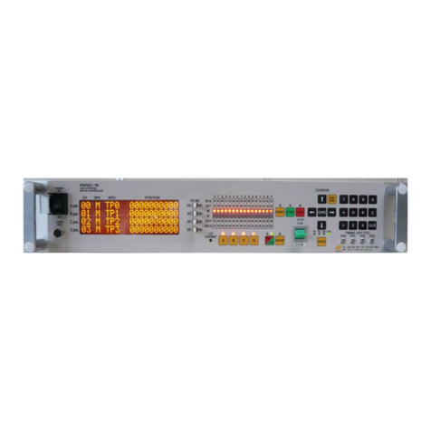
TSUJI ELECTRONICS PM16C-16HW2 User manual

16ch STEPPING MOTOR CONTROLLER
PM16C-16HW2
USER’S MANUAL
No. 4071(rev.4)
APPLICATION OF ELECTRONIC DEVICES
TSUJI ELECTRONIC CO., Ltd.
3739 Kandatsu-machi Tsuchiura-city
Ibaraki-Pre 300-0013 JAPAN
PHONE.+81-(0)29-832-3031 FAX. +81-(0)29-832-2662
URL http://www.tsujicon.jp/
E-mail info2@tsuji-denshi.co.jp

CONTENTS
1
CONTENTS
CONTENTS ............................................................................................................ 1
1 Abstract................................................................................................................ 4
1-1 Introduction.................................................................................................... 4
1-2 Architecture ................................................................................................... 5
1-3 Connection Diagram...................................................................................... 5
2 Parts names and function..................................................................................... 6
2-1 Front Panel.................................................................................................... 6
MOTOR STATUS LED.............................................................................. 7
2-2 Rear Panel .................................................................................................... 8
Pulse out Dub connector (PULSE)Pin assignment ............................... 8
Limit switch input Dsub connector(LS IN)Pin assignment...................... 9
RS-232C connector .................................................................................. 9
3 Preparation of a communication line.................................................................. 10
3-1 The outline of communication control.......................................................... 10
The display method of a SETUP screen................................................. 10
3-2 Configuration of LAN communication.......................................................... 10
3-3 Differences between LAN_L (normal LAN) and LAN_H (hi-speed LAN) ..... 10
3-4 Configuration of RS-232C and GP-IB communication..................................11
3-5 About delimiter character..............................................................................11
4 The outline of motor control................................................................................ 12
4-1 Remote mode and Local mode ................................................................... 12
4-2 Drive mode.................................................................................................. 12
4-3 Drive speed setting...................................................................................... 12
Constant drive (Const)............................................................................ 13
Trapezoidal form acceleration drive (Trape)............................................ 13
S shaped form acceleration drive (Schar)............................................... 13
4-4 Control screen............................................................................................. 14
Initial screen............................................................................................ 14
Motor drive screen.................................................................................. 14
Mode setup screen ................................................................................. 16
4-5 Home Position Set and Search drive........................................................... 17
At the beginning...................................................................................... 17
Selection of detecting ways .................................................................... 17
4-6 Hand box (Optional) .................................................................................... 21
04TYPE Hand box controller (PM16-HDX 4 axis control) .................... 22
02TYPE Hand box controller (PM16-HDX 2 axis simultaneous control)
22
16TYPE Hand box controller(PM16-HDX16 16 axis selected control)23
5 SETUP MODE.................................................................................................... 24
5-1 Page1 speed setting.................................................................................... 24
5-2 Page2 Motor operation, hold-off function setting......................................... 25
5-3 Page3 Limit switch setting........................................................................... 26
5-4 Page4 Digital limit switch setting ................................................................. 27
For digital limit switch.............................................................................. 27
5-5 Page5 REL/ABS/SCAN PRESET data setting ............................................ 28
5-6 Page6 Home position setting.................................................................... 29
5-7 Page7 TIMING OUT setting......................................................................... 30

CONTENTS
2
5-8 Page8 TIMING OUT channel setting ...........................................................31
5-9 Page9 Parameters of remote mode setting .................................................31
5-10 Page10A, 10B, 11A, 11B LAN setting........................................................32
5-11 Page12 Firmware version change and other settings................................33
6 Operation of Motor..............................................................................................34
6-1 Local mode operation ..................................................................................34
6-2 Remote/Local switching command ..............................................................34
6-3 Command to read out of motor status..........................................................35
Limit switch(LS) status read command....................................................36
Commands for current positon read or set..............................................37
6-4 Motor control command...............................................................................38
JOG step drive command........................................................................38
Speed select command...........................................................................38
Continuous move commands..................................................................39
Absolute drive command(ABS)...............................................................40
Relative drive command (REL) ...............................................................40
Home position return commands.............................................................42
6-5 STOP commands.........................................................................................42
6-6 Speed change command while driving ........................................................42
6-7 Command for Synchronous start for action pending....................................43
6-8 Command of SRQ output function...............................................................43
SRQ for GPIB communication.................................................................43
SRQ for LAN/RS-232C communication...................................................44
7 Commands for parameter set up........................................................................46
7-1 Basic configuration of motor ........................................................................46
7-2 Moving speed setting...................................................................................48
7-3 Acceleration and deceleration Rate Setting.................................................49
7-4 Details of acceleration / deceleration rate....................................................50
7-5 Setting of the limit switch-related .................................................................51
7-6 Setting of the home position related ............................................................52
7-7 Setting of the local mode data .....................................................................53
7-8 Display setting .............................................................................................54
8 Timing out signal output......................................................................................56
GATE signal ............................................................................................56
Pulse signal.............................................................................................56
Output method ........................................................................................57
Timing signal manual output mode..........................................................59
Timing output channel fixed mode...........................................................59
9 Other Operation..................................................................................................61
9-1 Channel comment setting............................................................................61
How to set the channel comments (local mode)......................................62
How to set the channel comments (remote mode)..................................63
9-2 All reply mode ..............................................................................................64
9-3 Maintenance command................................................................................65
10 Firmware version up.........................................................................................67
11 Appendix...........................................................................................................70
11-1 Command List............................................................................................70
11-2 Battery backup battery replacement...........................................................72
12 Revision History................................................................................................73

1 Abstract
4
1 Abstract
1-1 Introduction
Like the PM16C-HW, the PM16C-HW2 is a stepping motor controller that has two
Ethernet connection ports. It has 2 IP addresses and 8 connection ports for each IP address,
and high-speed Ethernet communication is possible. H LAN is a high-speed communication
LAN port that can read the location information of all 16 channels within 1ms. An operation
system is almost the same as PM16C-04XDL and PM16C-16.
The difference with PM16C-04XDL is described below.
1. PM16C-16HW2 controls 16 motors at the same time by Ethernet, RS-232C, and GP-IB
communication.
2. The command which reads the state of all channel was added.
3. “Answer all mode”which adds an answer to all the commands was added.
4. Two axis interpolation commands which starts with “C0” or “C1” and Oscillation drive
command which starts with “Y” are not mounted now
The difference with PM16C-16 is described below.
1. Independent IP addresses can be set for the two Ethernets. Each has 8 ports, and a total
of 16 locations can be connected at the same time.
2. Response time has been reduced to a maximum of 25ms for all commands.
3. With H_LAN, all 16ch positions can be read within 1ms.
4. The "STOPx" response, which is a pseudo SRQ signal related to "LN_SRQ", is sent to
the port that last sent "SRQx1" (x: 0 to F). The settings are independent for each
connection port.
Take over the following functions of PM16C-04XDL.
1. Count pulse step bit is 32bits. Numerical range is -2,147,483,647 to +2,147,483,647.
2. Each characteristics (HSPD, MSPD, LSPD, RATE, LMSW, DGLS)is available for
each channel.
3. Absolute position drive, relative position drive, continuous drive, and find home position
drive is available. These drive have 3 acceleration and deceleration mode, constant,
trapezoid, and “S” shaped.
4. The output of trigger pulse or gate signal (TTL) is available at the arbitrary sections and
intervals.
5. There are five kinds of the way of stopping motor.
by the limit switch signal
by the home position limit switch signal
by the digital limit switch signal
when the “STOP” button is pushed
when the stop command is published
6. Firmware ROM update via communication line is available.

1 Abstract
5
1-2 Architecture
1-3 Connection Diagram
LS Cable (Dsub 9pin)
Pulse Cable
(Dsub 9pin)
PM16C-HW2
Driver
Sensor
Pulse
Motor
PC
Sensor
Pulse
Motor
LAN Cable
RS-232C Cable
GP-IB Cable
Driver
RS-232C
GP-IB
Front panel
Control switch
FLSH ROM
for firmware
version up x 2
Data Memory
L LAN
CPU
LCD Display
Pulse output
connector
Limit switch
input
connector
FPGA
Pulse
controller
2ch x 8
Up to 16 set
connectable.
H LAN
(Hi-speed
LAN)

2 Parts names and function
6
2 Parts names and function
2-1 Front Panel
No.
Name
Function
1
POWER switch
This is the power switch of PM16C-16HW2.
2
Hand Box connector
Connect the Hand Box here (option).
See page 19.
3
LCD display
20 character and 4 line LCD.
Motor drive status and each channel data are
displayed here.
4
CH select switch
Any 16 motor channel is allocated toA, B, C, D
position. Select the motors to control with this switch.
In SETUP mode, setup channel No. is changeable
with a pos. ch select switch.
5
LCD contrast volume
Adjusts LCD contrast with + screw driver.
6
Motor active button
Set motor drive active or non-active for each position.
Bright position shows active state.
In local mode, motor drives active position only.
7
Motor status LED
These LED shows the motor status.
Details are shown at page 7.
8
PRESET button
When motor drive mode is scan, current pulse position
is set to preset value.
9
START button
All activated motor start driving according to the
motor drive mode.
10
STOP button
All activated driving motor stop at local mode. All
driving motor stop at remote mode.
11
REM/LOC button
Exchanges local mode and remote. If you push this
button when turning on the power, various types of
parameter except the current pulse value are
initialized.
12
SETUP button
Goes to motor initial data setting mode (SETUP)
when all motors are stop and local mode. If push it
again, exits SETUP mode.
1 3 4 7 8 9 10 15 16 17
2 5 6 11 12 13 14 18

2 Parts names and function
7
MOTOR STATUS LED
0 1
・・・ E F The channel is shown.
CW LS ●●
・・・
●●LED lights when CW direction limit switch is activated.
CW P ●●
・・・
●●LED lights when CW direction pulse is output.
MF ●●
・・・
●●LED lights when motor hold off signal is output.
HP ●●
・・・
●●LED lights when Home Position limit switch is activated.
CCW P ●●
・・・
●●LED lights when CCW direction pulse is output.
CCW LS
●●
・・・
●●LED lights when CCW direction limit switch is activated.
LED of limit switch blinks when digital limit switch described at page 25 was turned on.
No.
Name
Function
13
JOG switch
Starts CW or CCW JOG operation. Motor drives just
JOG set pulse with one push. If you hold over 0.4
sec., motor drives while holding.
In SETUP mode, changes the page of setup function.
14
MODE button
Select the drive mode when pushing start button.
Bright LED mode is selected mode.
Drive mode changes every pushing.
15
cursor button
Move the cursor position with these keys.
Changes set data at SETUP mode with “CHG”
button.
16
DSPCHG button
Exchanges motor drive screen and mode disp. screen.
17
numeric keys
Entry the numeric data at SETUP mode.
Sign inversion with “+-”button, data input cancel
with “CLR”button.
If you push “CLR”button when turning on the
power, pulse value of all channels are reset to zero.
18
TIMING/OUT connector
(LEMO)
TTL level pulse signal or gate signal according to
pulse position data are output. See ”8 Timing out
signal output”(Page 54) in details.

2 Parts names and function
8
5V 12V
OFF ON
2-2 Rear Panel
Pulse out Dub connector (PULSE)Pin assignment
No.
Name
Function
1
Pulse out connector
(PULSE)
Limit switch connector
(LS IN)
CH0 to CH15 pulse output Dsub9 female connector
and limit switch input Dsub9 male connector are
attached. Pin assignment are shown below.
2
GP-IB connector
Connect the GP-IB cable here.
3
RS-232 connector
Connect the RS-232C cross cable here.
4
H LAN connector
Connector for Hi-speed LAN (for command PC_16?)
Connect the LAN cable here.
Available to connect from 8 locations at the same
time.
5
L LAN connector
Connect the LAN cable here.
Available to connect from 8 locations at the same
time.
6
Fuse holder (250 V 3A)
250V, 3A fuse is equipped here.
7
Power cable connector
Insert attached AC cable here.
100 ~ 220VAC power is available.
dotted line is for + common driver
(in this case, 2, 4, 7 Pin are no
connection.)
300ohm
+
−
DRIVER
+
−
+
−
1 2 3 4 6
Function
Pin No.
CWP (PULSE) −
1
CWP (PULSE) +
2
CCWP (DIRECTION) −
3
CCWP (DIRECTION) +
4
F.G
5
HOLD OFF −
6
HOLD OFF +
7
(+5V)
8
N.C
9
5 7

2 Parts names and function
9
CWP (pins 1 and 2) and CCWP (pins 3 and 4) have a differential output of +5V-0V.
HOLD OFF (pin 6) is an open collector output. The
7th pin is set to +5V at the factory setting, but it is
possible to output +12V from the 7th pin of the
same channel by switching SW0~15
(corresponding to the ch number) to the +12V side.
For pin 8, +5V can be supplied by opening the top
lid and turning ON/OFF the red slide switch
(SW16) on the board behind the connector. The
factory setting is OFF.
Limit switch input Dsub connector(LS IN)Pin assignment
Both a-contact limit switch and b-contact are available.
Logic inverting is also available at PM16C-16HW2 settings.
Use Dsub connector which shell width is under 35mm, since each Dsub connector
pitch is 37.6mm.
DE-C1-J6 (JAE), XM2S-0911 (OMRON), HDE-CTF (HIROSE) etc. are
recommended connectors.
RS-232C connector
The pin assignment of Dsub 9pin connector at PM16C-
HW2 side is shown right. Use cross cable between
PM16C-16HW2 and your PC.
Function
Pin No.
-
1
RXD
2
TXD
3
-
4
GND
5
-
6
-
7
-
8
-
9
1Kohm
+12V 0V
CW LS
CCW LS
HP LS
using
proximity switch
(
-
)
12V
SIG
0V
1
P
LS
1
2
12V
SIG
0V
3
4
6
7
Function
Pin No.
CWLS+
1
CWLS-
2
CCWLS+
3
CCWLS-
4
F.G
5
HPLS+
6
HPLS-
7
+12V(MAX 0.8A)
8
F.G
9
12V
SIG
0V

3 Preparation of a communication line
10
3 Preparation of a communication line
3-1 The outline of communication control
PM16C-16HW2 is equipped communication control by LAN (2 ports), RS-232C, and GP-
IB as same as PM16C-16HW. Initial setting is required of each communications. Any initial
setting can be performed in SETUP mode.
The display method of a SETUP screen
After Power on, the 1.REM/LOC button is pushed
and a green LED is made turn on.
Since a screen will change if the 2.SETUP button
is pushed, please push down 3.JOG switch in the
direction of CW or CCW, and change a page.
3-2 Configuration of LAN communication
JOG switch is moved to theCW position several times,
and page 10 (LAN_H), page 11 (LAN_L) are displayed.
Right photograph is the state of initial setting, and MAC
address different for every equipment.
To change the IP address, port number, subnet mask, and
gateway address, move the blinking cursor with the
CURSOR button and enter the number directly with the
numeric keypad.
As for a port number, 10001 to 10999 is a recommended
value. There are eight port numbers [0] to [7] for each of
LAN_H and LAN_L, and you can check or change other
port numbers with the CH SEL lever switch or numeric
keypad at the bottom.
If change is completed, the SETUP button will be pushed, and escape from SETUP screen.
The change will be reflected. Please check that communication is established by the “VER?”
command etc.
3-3 Differences between LAN_L (normal LAN) and LAN_H (hi-speed
LAN)
The difference is that the hi-speed LAN port has a structure that can respond to the
command "PS_16?" That reads the counters for all 16 channels within 1ms. Responses other
than "PS_16?" on the hi-speed LAN port side are the same speed as normal LAN.
Normal LAN port also responds to the command "PS_16?", but the specifications are about
10 to 20ms.
1 2 3

3 Preparation of a communication line
11
3-4 Configuration of RS-232C and GP-IB communication
JOG switch is moved to the CW position several
times, and page 9 (right screen) are displayed. Right
photograph is the state of initial setting.
The blinking cursor is moved on the figure of B.RATE
by CURSOR button. If the central CHG button is
pushed, baud rate can be chosen from 1200, 2400,
4800, 9600, 19200, and 38400. It is only baud rate that
can set up and other values are being fixed to DATA BIT: 8, STOP BIT: 1, NO FLOW
CONTROL, NO PARITY.
Aconfiguration of GP-IB only sets up address. Acursor is moved on the figure of ADDRESS
and address is set up within the limits of 2 to 31.
IF change is completed, the SETUP button will be pushed, and escape from SETUP screen.
3-5 About delimiter character
The format of command is ASCII data, and the delimiter is CR + LF (0x0d + 0x0a).
After receiving CR + LF, command interpretation begins. When sending commands, “CR +
LF” must be added at the end of the command, though the “CR + LF”are omitted in the
command.

4 The outline of motor control
12
4 The outline of motor control
4-1 Remote mode and Local mode
PM16C-16HW2 have two ways of control mode, remote mode and local mode. In local
mode, PM16C-16HW2 controls motor with switches attached front panel and hand box.
Commands from communication line which drives motor and overwrite the motor setting are
invalid, but which reads the data are available.
In remote, switches attached front panel are unable except and .
4-2 Drive mode
There are 4 drive modes at motor control, ABS, REL, SCAN, and H.P.
In local mode, you can change the drive mode with . Current drive mode is indicated
by LED above . In remote mode, you can select drive mode with command directly.
・REL mode Relative pulse drive mode
LOCAL: Push , and motor drives toward the destination by
preset value from present position.
REMOTE: Motor drives by entered value.
・ABS mode Absolute pulse drive mode
LOCAL: Push , and motor drives to preset destination value.
REMOTE: Motor drives by entered position.
・SCAN mode Continuous drive mode to CW, CCW direction
LOCAL: Push , and click “CW or CCW” jog switch, motor
drives to dedicated direction continuously.
Apush on the PRESET button will set a pulse to the value set
up beforehand.
・HP mode Drive detecting origin point of pulse count for each channel.
Details are in chap5.6 “Home position setting”.
All motor drive are stopped with or limit switch or HP switch signal, or enter motor
stop command.
4-3 Drive speed setting
High speed (HSPD), middle speed (MSPD), low speed (LSPD) and acceleration rate is set
individually for each channel. These setting are modified by remote commands or SETUP
mode “5-1 Page1 speed setting (Page 24)”.
Acceleration and deceleration method have the three modes, “Const”, “Trape”, and “Schar”.
These setting are modified by remote commands or SETUP mode “5-2 Page2 Motor
operation, hold-off function setting (Page 23)”. Refer to the page 48 for the setting command
of speed.
STOP
REM
LOC
MODE
START
STOP
MODE
START
START

4 The outline of motor control
13
Speed
Time
stop command
start command
MAX SPEED (= HSPD/MSPD/LSPD)
Speed
Time
MAX SPEED(= HSPD/MSPD)
A
B
stop command
start command
START and END
speed (= LSPD)
acceleration curve
(= RATE)
Max speed > 1500000, A, B = 80000 pps
Max speed > 150000, A, B = 10000 pps
Max speed <= 150000, A, B = 1000 pps
Constant drive (Const)
Motor drives at MAX speed as soon as drive execution, and stops immediately as
soon as stop operation. Too fast drive speed causes motor step out.
Low speed drive is always constant drive at all drive mode.
Trapezoidal form acceleration drive (Trape)
Acceleration operation is carried out until it will reach MSPD or HSPD by making
LSPD into initial velocity, if a motion command is executed.
When a stop command is input, the motor starts deceleration. And the motor stop
when speed reached LSPD. Acceleration and deceleration curve become rapid, and
time to reach maximum speed shortens so that Rate value shown by acceleration and
deceleration code (See page 48) is large.
Large value of "LSPD" may not make smooth start of the motor.
S shaped form acceleration drive (Schar)
stop command
acceleration curve
(= RATE)
Speed
Time
MAX SPEED (= HSPD/MSPD)
START and END
speed (= LSPD)
start command

4 The outline of motor control
14
Although it is fundamentally the same as trapezoidal form acceleration drive, the
velocity change at the time of acceleration and deceleration start and the time of
acceleration and deceleration stop is performed according to S shaped form
approximated to the parabola.
Large value of "LSPD" may not make smooth start of the motor.
The acceleration / deceleration curve start area Aand end area B fluctuate according
to the maximum speed.
When LSPD + 1000pps <= HSPD, automatic calculation is performed so that the
curve becomes smooth.
4-4 Control screen
Initial screen
Current firmware version is displayed at screen just after turning on the power.
(Firmware version 1.08 or later does not display the version on the upper screen, but
automatically switches to the following page and the firmware and hardware
versions are displayed.)
Motor drive screen
APos.
B Pos.
C Pos.
D Pos.
This is default screen when you control the motors. 4 channels which allocated Pos.
Ato D pulse position are displayed. Colored area means cursor moveable area at local
mode.
1
2
3
4
5
0 0 H T P 0 0 1 2 3 4 5 6 7 8 9
0 1 H # T P 1 - 0 1 2 3 4 5 6 7 8 9
0 2 M # T P 2 - 0 1 2 3 4 5 6 7 8 9
1 5 L T P 3 0 1 2 3 4 5 6 7 8 9
* * * * P M 1 6 C - 1 6 H W 2 * * * * *
F I R M W A R E V e r . < 1 . 0 8 >
H A R D W A R E V e r . : 3
* * * * P M 1 6 C - 1 6 H W 2 * * * * *
S T E P P I N G M O T O R
C O N T R O L L E R V e r < 1 . 0 0 >
T S U J I - D E N S H I C o . L T D ,

4 The outline of motor control
15
No.
Data
Function
1
Channel No.
The display of the allocated channel at Ato D Position.
You can change these channel with “CH SEL”switch
and numeric keys. The same channel at two position is
prohibited.
2
Drive speed
You can select motor driving speed from “HSPD”,
“MSPD”, and “LSPD”with “CHG”button. Please
check the exact speed at SETUPmode 5-1 Page1 speed
setting (page 24) or remote commands.
3
Timing signal
The display of timing out signal status.
If displayed “#”here, timing out signal output status is
ready. If not, signal is not outputted.
Each time the “CHG”button is pushed, a state changes.
See “8 Timing out signal output” (page 54) in detail.
4
Timing signal output port
Channel comment
The display of channel comments can be switched, and
comments can be displayed on each channel using 3
alphanumerical characters. For comment settings, refer
to "9-1 Channel comment setting" (page 59).
With the CHG button, when this display and timing
signal are output, you can switch the display indicated
by TP0-3 from which port to output. If it is not assigned
to any port, "---" is displayed.
(V1.08 ~) Battery When the backup battery (CR2032)
becomes empty and various settings cannot be saved,
"BATT EMPTY" is displayed at regular intervals in this
column. If this symptom does not improve after turning
the power off and then on again, replace the battery.
5
Current pulse position
Displays current pulse position for each position.

4 The outline of motor control
16
Mode setup screen
Push 1: at motor drive screen, display changes into mode setup screen.
On this screen, various parameter setup at the time
of a motor drive is performed.
Push 2: , changes motor active mode “REL
−> ABS −> SCN −> H.P −> REL”. Setting value
differ in each mode.
LED on the 3: blinks during mode setup
screen.
Display value for each motor active mode are below.
REL : Enter relative drive pulse value when you push .
ABS : Enter absolute drive pulse value when you push .
SCN : Enter preset value when you push .
H.P : If you have found the home position at this position, displays
its data. If not, displays “NO_HOME POS.”. Home position data
is rewritable if you have found it.
When you change these values, move the cursor where you change with cursor button and
enter the new value with numeric keys. Inverts the Sign of value with , resets entering
value with .
Entering value is displayed with zero suppression. If you move cursor up and down, entering
value is fixed and displayed with zero-fill.
0 0 M R E L 0 1 2 3 4 5 6 7 8 9
0 1 M R E L - 0 1 2 3 4 5 6 7 8 9
0 2 M R E L - 0 1 2 3 4 5 6 7 8 9
1 5 L R E L 0 1 2 3 4 5 6 7 8 9
1
2
3
DSP
CHG
MODE
SETUP
START
START
PRESET
±
CLR

4 The outline of motor control
17
4-5 Home Position Set and Search drive
Home position of the unit is set by home position search drive. If the sensor of the origin
point (H.P switch) is detected, motor will stop automatically and the moving direction and
the origin point at the time of detection are memorized on a main unit.
At the beginning
A setup of H.P can be set up by connecting with H.P LS switch of LS connector and
detecting the origin point sensor arranged at the mechanical origin point.
To set H.P, you need to decide the direction of detecting origin point.
In the case of the following figure, detect way is CW.
Once detect the origin point, motor stopped automatically and memorize the direction
and H.Ppulse data. In this case, motor speed must be low within response time of sensor.
You need to check the set speed.
Selection of detecting ways
There are three ways of detecting origin point.
Some are in case of memorized data had existed and another is in case of no memorized
data.
[METHOD A]
METHOD
ORIGINAL
STATE
DETECT WAY
PROCEDURES
ACCURACY
TIME
A
NO
MEMORIZED
DATA
MANUAL
Manual operation
JOG CW, CCW or
START + JOG
CW,CCW
AVERAGE
SHORT
B
NO
MEMORIZED
DATA
SEMI
AUTOMATICAL
Hold “START” switch
more than 1 sec.
GREAT
LONG
C
EXISTED
MEMORIZED
DATA
SEMI
AUTOMATICAL
Push “START” switch.
GREAT
SHORT
CW
CCW
origin sensor (H.P LS)
CW
CCW
origin sensor (H.P LS)
mechanical cam for detect origin point
mechanical cam for detect origin point

4 The outline of motor control
18
When you set H.P to direction CW, you have to set motor position to CCW side against
origin sensor, then move motor from CCW to CW side by operation switch
JOG CW or START + JOG CW.
Once detect the origin point, motor stopped suddenly, origin point procedures finished.
Then the position of pulse data is memorized and the direction approaching a sensor is
also memorized. (In the case of the above figure the CW direction)
This way is applicable also to the detection in the case of using HP sensor as CWLS or
CCWLS. (In that case, input CWLS or CCWLS also into HPLS)
..................................................................................................................................
[METHOD B]
The following example is the case that the direction of the origin point detection is CW.
The start direction of the origin point detection set in the opposite direction of the
direction of the origin point detection.
(You can set at “Page6 Home position setting

4 The outline of motor control
19
Page6 Home position setting” (Page 29))
(a). In case of start position is in CW side against origin point
(b). In case of start position is in CCW side against origin point
Cam
CW
CCW
origin sensor (H.P LS)
2. Detect the origin point then back
to CW side at low speed.
1. It starts present speed H, M, L.
3. Again detect the origin point at low speed.
Cam
CW
CCW
origin sensor (H.P LS)
2. Detect the CCW limit switch then back to CW side.
1. It starts present speed H, M, L.
3. Detect the origin point then goes to
CCW side at low speed.
CCW limit switch
4. Again moveto CWside and detect
the origin point and stop.
Table of contents
Other TSUJI ELECTRONICS Controllers manuals

