TUL PYNQ-ZU User manual

1
PYNQ-ZU
Reference Manual v1.2

2
Revision HistoryV1.2
07/09/2021
Data
Version
Revision
07/31/2020
V1.0
•Updated Logo
•Updated Contents, Added Hierachy
•Put credits and reference for pictures used
•Add intended audience,
•Add intended applications,
•Add tool support – PYNQ, Vitis, Vitis AI and Vivado
•Replace with Board requirements document diagram
•Update the board picture
06/17/2021
V1.1
•Updated Contents
•Update final image
•Add labels for main components
•Add Board Component Description
•Updated Block Diagram of Board
•Add image/diagram of HDMI ports
•Add diagram of WIFI-BT
•Add image of USB3.0 ports
•Add image/diagram of AUDIO ports
•Add Standard Peripheral of SYZYGY ports
•Add image/diagram of XADC ports
•Delete all schematics
07/09/2021
V1.2
•Updated Figure 3-3
•Add form of Raspberry Pi GPIOs

3
Table of Contents
Introduction.................................................................................................................................5
Overview.................................................................................................................................5
Target Audience..................................................................................................................7
Target Applications ............................................................................................................7
Tool Support .......................................................................................................................7
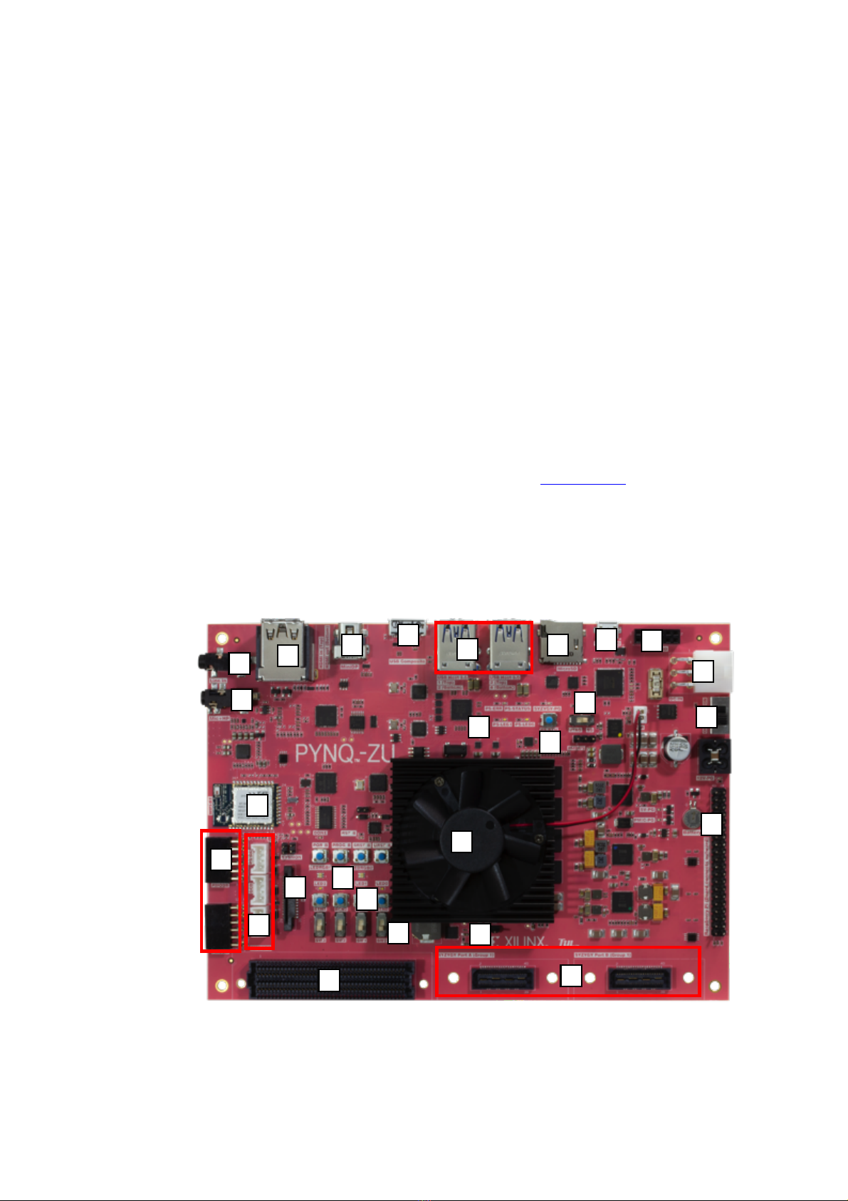
Block Diagram........................................................................................................................8
Board Features ........................................................................................................................9
Board Specifications.............................................................................................................10
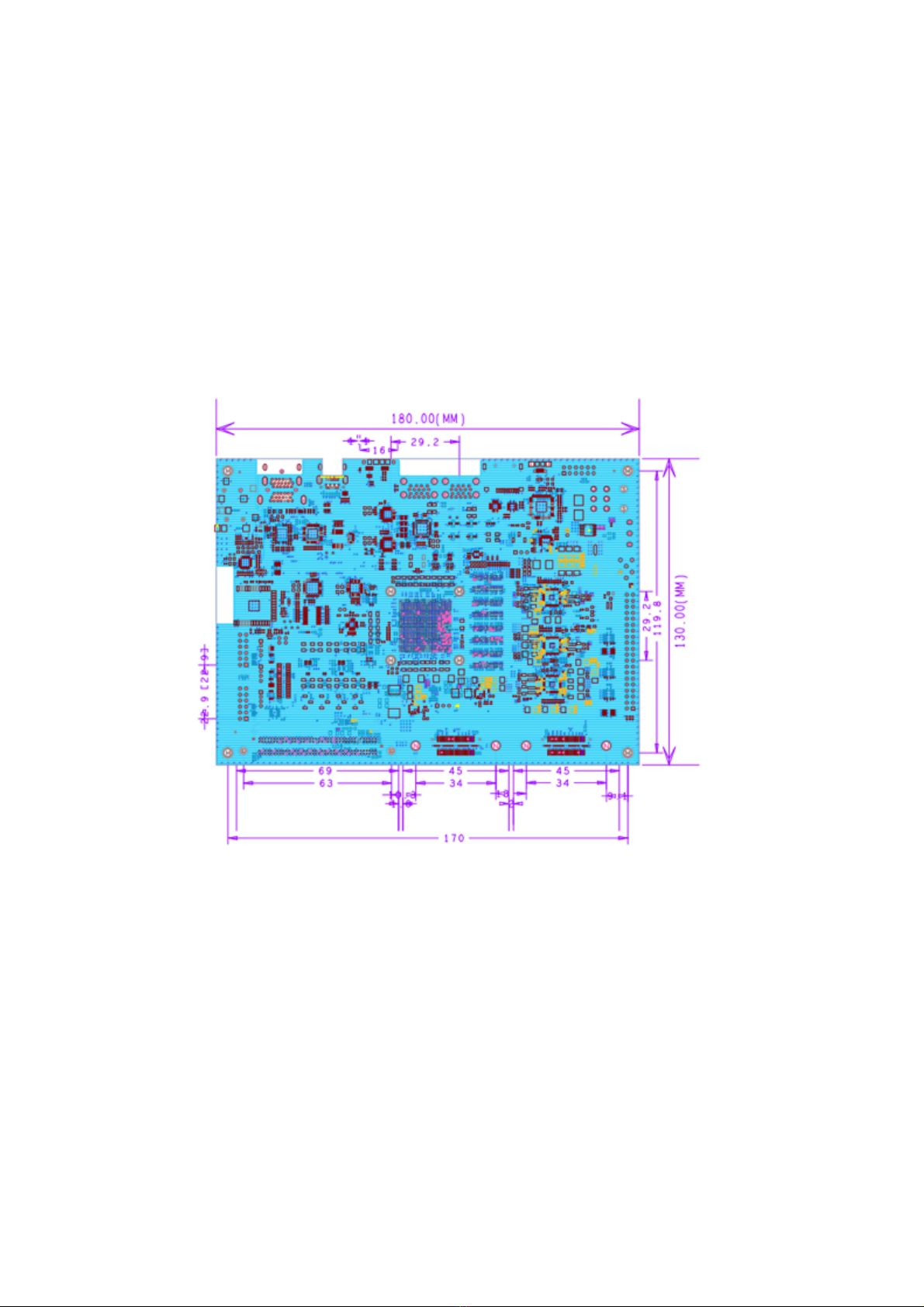
Dimensions .......................................................................................................................10
Board Component Descriptions................................................................................................10
Power ....................................................................................................................................10
Boot Mode Selection ............................................................................................................12
PS Connected Peripherals.....................................................................................................13
Clock Sources ...................................................................................................................13
DRAM ..............................................................................................................................14
Micro SD ..........................................................................................................................15
PS I2C MUX.....................................................................................................................16
PS Composite USB...........................................................................................................17
PS USB 3.0 Hub ...............................................................................................................18
PS Mini Display Port ........................................................................................................20
Wifi+BT............................................................................................................................20
PL connected peripherals......................................................................................................22
HDMI Video TX...............................................................................................................22
HDMI Video RX ..............................................................................................................22
AUDIO .............................................................................................................................25

4
User I/O ............................................................................................................................27
MIPI CSI...........................................................................................................................30
PMOD...............................................................................................................................31
FMC LPC..........................................................................................................................32
Dual SYZYGY Standard Ports.........................................................................................34
GROVE Interface .............................................................................................................37
Raspberry Pi GPIOs..........................................................................................................37
TPM PMOD......................................................................................................................39
External Analog Inputs .....................................................................................................39

5
Introduction
Overview
The PYNQ-ZU is a Zynq® UltraScale+™ XCZU5EG-1SFVC784 MPSoCdevelopment
board designed to be used with the PYNQ™open-source framework.
To find out more about PYNQ, please see the project webpage at www.pynq.io. Here you will
find materials to help you get started with PYNQ and a forum for contacting the supporting
community.
The photo of the platform is shown below Figure 1-1
Figure 1-1
1
17
18
19
20
21
16
15
14
13
11
12
10
8
7
6
5
4
3
2
9
23
24
25
22
26

6
Table :PYNQ-ZU Board Component Description
Callout
Component Description
1
XCZU5EG-1SFVC784
2
LEDs(x4,PL),LED RGB(x2,PL)
3
Button(x4,PL)
4
Switch(x4,PL)
5
FMC-LPC
6
ADC
7
SYZYGY Standard connector (x2)
8
40-Pin Raspberry PI connector
9
Power switch
10
Power-IN
11
Pmod (x1 PS Pmod-TPM)
12
Micro USB UART
13
MicroSD
14
USB 3.0 Hub
15
Composite USB 3.0
16
Mini Display Port
17
Audio (MIC+HP)
18
Audio (LINE-IN)
19
Wifi + BT
20
Pmod (x2)
21
MIPI CSI
22
Grove connectors (x3)
23
LEDs (x2,PS)
24
Button(x1,PS)
25
JTAG-SD boot mode switch
26
HDMI Video TX & RX (banked)

7
Target User
The board supports the following developer and user persona:
•Hardware designers who want to design a system, at an RTL or system level, using
Vivado IPI tools, to use the interfaces available on the board
•Embedded software engineers who like to develop embedded systems using Vivado IPI,
Vivado/Vitis HLS, and Vitis embedded development software
•Domain experts software engineers/developers who like to develop applications in
Python using PYNQ framework or C/C++ language
Target Applications
•parallel hardware execution
•high frame-rate video processing
•hardware accelerated algorithms
•real-time signal processing
•high bandwidth IO
•low latency control
Tools Support
The PYNQ-ZU platform is supported by the PYNQ framework, and Vitis, Vitis AI, and
Vivado tools.

8
Block Diagram
The PYNQ-ZU board block diagram is shown in Figure 1-2.
Figure 1-2

9
Board Features
The PYNQ-ZU board features are listed here. Detail information for each feature is provide in
Board Component Descriptions.
Device: Zynq Ultrascale+™ MPSOC XCZU5EG-1SFVC784
FPGA Clocks
ØPL-Clocks
ØUser-Clock
ØGTR-USB3.0-Clock
ØGTR-DP-Clock
PS Connected peripherals
ØMicro USB UART
ØMicroSD
Ø4GB DDR4
ØComposite USB 3.0
ØUSB 3.0 Hub
ØMini Display Port
ØWifi + BT
ØUser LEDs (x2)
ØXADC pins (x2)
ØPmod (x1 PS Pmod-TPM)
ØGrove connectors (x1)
PL Connected peripherals
ØAudio (MIC+HP, Line In)
ØHDMI Video TX
ØHDMI Video RX
ØRGB LEDs (x2)
ØUser LEDs (x4)
ØDIP switches (x4)
ØPushbuttons (x4)
ØMIPI CSI
ØPmod (x2)
ØFMC LPC
ØSYZYGY Standard connector (x2)
ØGrove connectors (x2)
Ø40-Pin Raspberry PI connector

10
Board Specifications
Dimensions
Width: 180mm
Length:130mm
Board Component Descriptions
Power
The PYNQ-ZU must be powered from an external 12V DC power supply. The Power Jack is
DC-IN.

11
Power switch is shown in Figure 3-1.
Figure 3-1
DC-IN
Power
switch

12
Boot mode selection
The PYNQ-ZU supports MicroSD and JTAG boot modes. The boot mode is selected using the
JTAG SD DIP switch. To select the JTAG mode, slide the switch to the left. To select MicroSD
mode, slide the switch to the right. The switch is shown in Figure 3-2.
Figure 3-2 Boot Mode Switch
Boot Mode
switch
JTAG SD

13
PS connected peripherals
Clock Sources
The PYNQ-ZU board provides fixed clock sources for XCZU5EG MPSOC.Table 3-1 lists
various clock names, their frequencies, and the clock sources used to generate them.
Table 3-2 lists FPGA pins to which the generated clocks are sourced.
Table 3-1
Clock Name
Frequency
Clock Source
Fixed Frequency Clock
GTR_REF_DP_CLK
27MHz
Si5340A Clock Generator
GTR_REF_USB30_CLK
26MHz
FPGA_CLK125
125MHz
FPGA_USER_CLOCK
156.25MHz
PS_REF_CLK
33.333MHz
OSC
Table 3-2 Clock Connections, Source to XCZU5EG MPSOC
Schematic Net Name
FPGA Pin
GTR_REF_DP_CLK_P
E21
GTR_REF_DP_CLK_N
E22
GTR_REF_USB30_CLK_P
F23
GTR_REF_USB30_CLK_N
F24
FPGA_CLK125_P
K4
FPGA_CLK125_N
K3
FPGA_USER_CLOCK_P
AD5
FPGA_USER_CLOCK_N
AD4

14
DRAM
The PYNQ-ZU includes four Micron 512Mx16 DDR4 memory.
Each MT40A512M16JY-083E has a 16-bit wide interface with a total capacity of 1GB. The
four modules combine to provide a 64-bit data path.The DDR4 is connected to the hard
memory controller in the Processor Subsystem (PS).
The PS DDR4 memory controller supports speeds of up to 2400MT/s on the PYNQ-ZU
board.
The DDR4 configuration of the PYNQ-ZU board is shown in Figure 3-3.
Figure 3-3 DDR4 Configuration in Vivado

15
Micro SD
The PYNQ-ZU has a MicroSD slot (SD0). An SD card can be used to boot the board,
or for applications that require non-volatile external memory storage.
MIO
Name
13
MIO13_SDIO_D0
14
MIO14_SDIO_D1
15
MIO15_SDIO_D2
16
MIO16_SDIO_D3
21
MIO21_SDIO_CMD
22
MIO22_SDIO_CLK
24
MIO24_SDIO_CD

16
PS I2C MUX
The PS-side I2C0 interface provides access to I2C peripherals through a set of I2C . The
system controller connected to the PL-side by the I2C0_SDA/SCL Bus. Figure 3-4 shows a
high-level view of the I2C0 bus connectivity represented in below table. TCA9548A is set to
0x75.
Figure 3-4 I2C0 Bus Topology
I2C Mux(Addr 0x75) Port
I2C BUS Device
I2C Address
0
PMBUS
attached device dependent
1
Si5340A Clock
0x74
2
AUDIO
0x6E
3
CAM MIPI
attached device dependent
4
SYZYGY
Port A(0x32)
Port B(0x3D)
5
FMC_LPC
attached device dependent
6
USB5744
attached device dependent
PS BANK500
PS I2C0
MIO18/
MIO19
TCA9548A
I2C0_SDA/SCL
SDA
SCL
SD0/SC0
SD1/SC1
SD2/SC2
SD3/SC3
SD4/SC4
SD5/SC5
SD6/SC6
PMBUS_SDA/SCL
Si5340A_SDA/SCL
AUDIO_SDA/SCL
CAM_SDA/SCL
SYZYGY_SDA/SCL
FMC_LPC_IIC_SDA/SCL
USB5744_SDA/SCL

17
PS Composite USB
The PYNQ-ZU board uses a Standard Microsystems Corporation USB3320 USB 2.0 ULPI
Transceiver to support a USB connection to the host computer (see Figure 3-5). The
USB3320 is a high-speed USB 2.0 PHY supporting the UTMI+ low pin interface (ULPI)
interface standard.
Figure 3-5 USB Interface
The USB3320 is clocked by a 24 MHz crystal.
The interface to the USB3320 PHY is implemented through the IP in the XCZU5EG MPSoC
Processor System (PS).
USB 2.0 ULPI Upstream Connections to the XCZU5EG MPSoC
XCZU5EG
Pin
Net Name
USB3320
Pin Number
Pin Name
AB21 & P16
USB_RST_B
27
RESET_B
F18
MIO58_USB0_STP
29
STP
D16
MIO53_USB0_DIR
31
DIR
G18
MIO52_USB0_CLK
1
CLKOUT
B16
MIO55_USB0_NXT
2
NXT
C16
MIO56_USB0_DATA0
3
DATA0
A16
MIO57_USB0_DATA1
4
DATA1
F17
MIO54_USB0_DATA2
5
DATA2
E17
MIO59_USB0_DATA3
6
DATA3
C17
MIO60_USB0_DATA4
7
DATA4
D17
MIO61_USB0_DATA5
9
DATA5
A17
MIO62_USB0_DATA6
10
DATA6
E18
MIO63_USB0_DATA7
13
DATA7
USB3320
USB2.0

18
USB3.0 GTR
XCZU5EG Pin
Net Name
USB Connect Name
C25
GTR_LANE2_TX_P
SSTX+
C26
GTR_LANE2_TX_N
SSTX-
B27
GTR_LANE2_RX_P
SSRX+
B28
GTR_LANE2_RX_N
SSRX-
PS USB 3.0 Hub
The PYNQ-ZU board uses a Microchip USB5744 USB Controller Smart Hub to support a
USB Hub to the slave device(see Figure 3-6). Microchip USB5744 4-Port
SuperSpeed/High-speed USB Controller Smart Hub provides low-power, OEM
configurability, and advanced features for embedded USB applications. All enabled
downstream ports are supported through 5Gbps SuperSpeed (SS), 480Mbps Hi-Speed (HS),
12Mbps Full-Speed (FS), and 1.5Mbps Low-Speed (LS) USB downstream devices. USB 3.0
Hub is shown in Figure 3-7.
ULPI
GTR TX, RX
Figure 3-6 USB Hub
USB
MIO
USB
GTR
USB3320
ULPI
Downstream
USB5744
Hub
4 Port
USB3
Connect

19
Figure 3-7
USB 2.0 ULPI Downstream Connections to the XCZU5EG MPSoC
XCZU5EG
Pin
Net Name
USB3320
Pin Number
Pin Name
AB21 & P16
USB_RST_B
27
RESET_B
C19
MIO70_USB1_STP
29
STP
A18
MIO65_USB1_DIR
31
DIR
E19
MIO64_USB1_CLK
1
CLKOUT
B18
MIO67_USB1_NXT
2
NXT
C18
MIO68_USB1_DATA0
3
DATA0
D19
MIO69_USB1_DATA1
4
DATA1
G19
MIO66_USB1_DATA2
5
DATA2
B19
MIO71_USB1_DATA3
6
DATA3
G20
MIO72_USB0_DATA4
7
DATA4
G21
MIO73_USB0_DATA5
9
DATA5
D20
MIO74_USB0_DATA6
10
DATA6
A19
MIO75_USB0_DATA7
13
DATA7
USB 3.0 Hub

20
USB3.0 GTR
XCZU5EG Pin
Net Name
USB5744
B23
GTR_LANE3_TX_P
USB3DM_TXUP
B24
GTR_LANE3_TX_N
USB3DP_TXUP
A25
GTR_LANE3_RX_P
USB3DM_RXUP
A26
GTR_LANE3_RX_N
USB3DP_RXUP
PS Mini Display Port
The PYNQ-ZU contain a Mini Display Port. The Zynq UltraScale+ MPSoC provides a VESA
DisplayPort 1.2 source-only controller that supports up to two lanes of main link data at rates
of 1.62 Gb/s, 2.70 Gb/s, or 5.40 Gb/s. The DisplayPort standard defines an auxiliary channel
that uses LVDS signaling at a 1 Mb/s data rate, which is translated from single-ended MIO
signals to the differential DisplayPort AUX channel.
Wifi+BT
The PYNQ-ZU contain a Wifi + BT Module ATWILC3000-MR110CA. The
ATWILC3000-MR110CA module is an IEEE 802.11 b/g/n RF/Baseband/Medium Access
Control(MAC) link controller and Bluetooth 4.0 compliant module, optimized for low power
mobile applications.This module supports single stream 1x1 IEEE 802.11n mode providing
up to 72 Mbps PHY rate. TheATWILC3000-MR110CA module features small form factor
when integrating Power Amplifier (PA), LowNoise Amplifier (LNA), Transmit/Receive
switch, Power Management, and chip Antenna. This module offers very low power
consumption while simultaneously providing high performance.
Table of contents
Other TUL Motherboard manuals