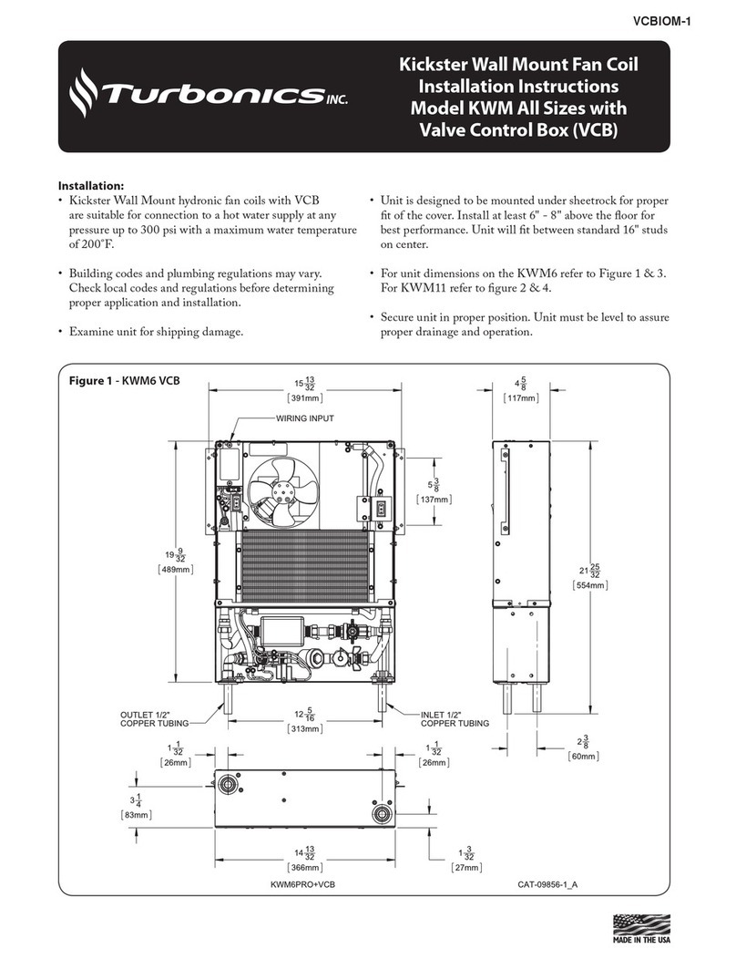
Piping:
• e piping to the unit will usually be copper or any other
locally approved piping. Accessible 1/2" sweat ttings are
provided on the unit itself. An optional exible stainless
steel connector kit with shut-o valves is available for
connecting the unit to any type of piping system.
• All piping systems should be designed by a technician
with experience in the various piping arrangements that
work with this type of unit.
• As with any system employing circulated water, the pipes
passing through unheated spaces should be insulated.
• When using mono-o or venturi ttings, we suggest
placements of a ball valve just after the supply take-o and
before the return is connected.
Piping: Hot Water Boiler
• e unit supply line should be taken from the boiler
side beyond any o-control valve. If the system being
used is a gravity-ow or cast-iron hot water system, a
separate circuit must be installed.
Piping: Water Heater
• To install correctly, a technician with knowledge of
piping arrangements and back-o valves must design the
piping system.
Wiring the Unit
• A eld wiring connection is provided on the unit.
Connect wires at this point only. See wiring diagrams
on the following page. Figure 4 for T45/T68/T12 and
Figure 5 for T13/T16.
• e unit is manufactured with a built-in factory wired
aquastat with a set point of 140°F on and 110°F o. e
aquastat may be disabled in the eld if not required.
• Unit is pre-wired from the factory on Lo speed. Unit
may be optionally installed with a remote mounted line
voltage thermostat.
• Speed switch (included) and/or a line voltage thermostat.
• All wiring should be done to all local and national codes.
Completion
• Secure unit to oor through holes on perimeter of the
bottom plate (screws provided).
• Bleed the unit, secure the access panel; and install front
grille cover.


