TUYA TYDE 3.0 User manual

User Instructions for TYDE3.0 Tuya Smart IoT Development BoardContents
Contents
1 Introduction 2
2 Introduce of Hardware Platform 4
3 Precautions and Recommended Steps for Use 6
3.1 Precautions . . . . . . . . . . . . . . . . . . . . . . . . . . . . . . . 6
3.2 Recommended Steps for Use . . . . . . . . . . . . . . . . . . . . . . 6
4 Self-testing and Inspection of Development Board 7
5 Experience of Development Board by Tuya Smart App 9
5.1 Downloading of Tuya Smart App . . . . . . . . . . . . . . . . . . . . . 9
5.2 Adding of Development Board by App . . . . . . . . . . . . . . . . . . 9
6 Commencement of Development of Smart Hardware Products 27
6.1 Register an account . . . . . . . . . . . . . . . . . . . . . . . . . . . 27
6.2 Creating a product . . . . . . . . . . . . . . . . . . . . . . . . . . . . 27
6.3 Downloading MCU Communication Protocol and SDK . . . . . . . . . . 27
6.4 MCU Programing . . . . . . . . . . . . . . . . . . . . . . . . . . . . . 28
7 Module Firmware Programing for STM32 and TYWE1S 29
7.1 STM32 Using Serial Port Downloader . . . . . . . . . . . . . . . . . . 29
7.2 STM32 Using ST-Link Downloader . . . . . . . . . . . . . . . . . . . . 35
7.3 STM32 Using J-Link Downloader . . . . . . . . . . . . . . . . . . . . . 36
7.4 Serial Port Downloader for Wi-Fi Module . . . . . . . . . . . . . . . . . 36
8 Conclusions 38
i

User Instructions for TYDE3.0 Tuya Smart IoT Development Board
Contents
1 / 38

User Instructions for TYDE3.0 Tuya Smart IoT Development Board1 INTRODUCTION
1 Introduction
TYDE3.0 Tuya Smart IoT development board is an IoT prototype platform provided
by Hangzhou Tuya Information Technology. Developers can quickly realize all kinds
of hardware demo by using TYDE3.0. To make hardware smart, they will need pro-
fessional support team in smart cloud platform, mobile App and Wi-Fi networking
module besides hardware. TYDE3.0 integrates the Wi-Fi module and MCU, connects
the Tuya Cloud and App. Developers can experience the use of IoT products once
they get the development boards. The development board is equipped with the
STM32F103C8T6 so developers can start development instantly after they get it
and enjoy developing smart hardwares. TYDE3.0 helps:
•Embedded software engineers of manufacturers to use TYDE3.0 for early-
stage development and debugging of embedded software program.
•App developers to use TYDE3.0 for App development and debugging before
the hardware control board is available.
•Makers to use TYDE3.0 to quickly realize the hardware demo and use mobile
phone to control hardware.
•IoT technophiles to understand the principles of IoT and learn the smart hard-
ware product development.
1.0.1 Recommendations on how to use TYDE3.0:
Steps Description Quick Link
Get familiar with
functions of the
development
board
Introduction of main parts and
components of the development board
and use of each button
Introduction of
TYDE3.0
hardware
platform
Try Tuya Smart
App
TYDE3.0 has built-in demo hardware,
and users can add it directly on Tuya
Smart App to experience the whole
process.
Try to use the
Tuya Smart App
development
board
2 / 38

User Instructions for TYDE3.0 Tuya Smart IoT Development Board1 INTRODUCTION
Steps Description Quick Link
Start smart
hardware product
development
Register an account in Tuya
Development Platform and start your
own smart hardware development.
Start smart
hardware
product
development
3 / 38

User Instructions for TYDE3.0 Tuya Smart IoT Development Board2 INTRODUCE OF HARDWARE PLATFORM
2 Introduce of Hardware Platform
The Wi-Fi module of TYDE3.0 development board will be the high performance Wi-Fi
module TYWE1S developed by Tuya or ESP-12F developed by the Ai-Thinker. Both
TYWE1S and ESP-12F use Espressif ESP8266 Wi-Fi chips. The development board in-
cludes Wi-Fi MODULE, STM32F103C8T6 single Chip microcomputer, USB-serial port
conversion chip and multiple LED indicator lights, IO interfaces for development by
developers and power, etc. It can be an MCU for users and connected to Wi-Fi mod-
ule of built-in Tuya Smart firmware, and it can also be used by users to experience
the operation performance of all types of Tuya Smart products. For developers in
enterprises, it accelerates the progress of projects and product development. The
development board is powered up through a USB MICRO-B port and builds in a USB-
to-serial circuit, for users to conduct module test upgrade and project development
in a convenient, quick, and flexible way. The details are given in the following fig-
ure.
4 / 38

User Instructions for TYDE3.0 Tuya Smart IoT Development Board2 INTRODUCE OF HARDWARE PLATFORM
Functions of interfaces are given below:
• 1、ST-Link programing port: program downloading port in SWD mode for STM32
single-chip microcomputer;
• 2、MCU BOOT button: must be pressed during serial programing;
• 3、MCU RESET button: hardware reset button of STM32 single-chip microcom-
puter;
• 4、Firmware programing port of the TYWE1S Wi-Fi module: it is used to check
the operation information of the TYWE1S module and program the TYWE1S
firmware (Please do not program the firmware by yourself, and do contact our
company if you need to program it.).
• 5、Firmware programing port of ESP-12F Wi-Fi module: it is used to check the op-
eration information of ESP-12F module and program ESP-12F firmware (Please
do not program the firmware by yourself, and do contact our company if you
need to program it.).
• 6、Wi-Fi reset button: both TYWE1S and ESP-12F Wi-Fi module use the hardware
reset.
• 7、Wi-Fi boot button: it is used when programing hardwares in TYWE1S and
ESP-12F Wi-Fi modules.
• 8、MCU is connected to the serial port of the Wi-Fi module. When the short-
circuit block is plugged, the MCU is connected to the serial port of the Wi-Fi
module.
• 9、MCU is connected to the serial port of the serial port chip of USB. When
the short-circuit block is plugged, the MCU is connected to the serial port of
CP2102 chip.
• 10、5V power port: output 5V voltage and GND
• 11、USB port: USB Micro-B port, it is connected to USB of computers
• 12、3.3V power port: output 3.3V voltage and GND
• 13、MCU I/O port: I/O pin of MCU, for users’ own development
• 14、Buttons: have two buttons, connected to the I/O pin of MCU
• 15、LED indicators: LED1 and LED2 are connected to MCU, LED3 is connected
to Wi-Fi module, on at low level
• 16、RGB colored indicator: connected to MCU, on at low level.
5 / 38

User Instructions for TYDE3.0 Tuya Smart IoT Development Board3 PRECAUTIONS AND RECOMMENDED STEPS FOR USE
3 Precautions and Recommended Steps for Use
3.1 Precautions
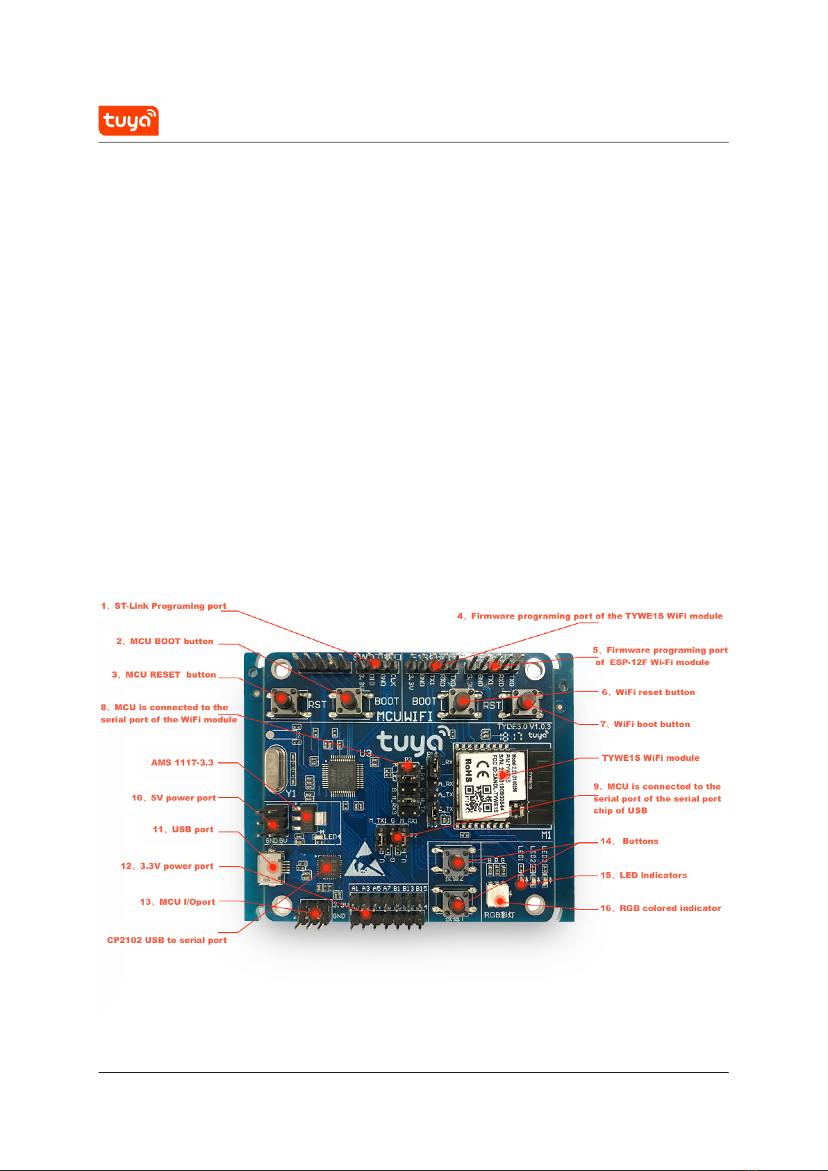
1. TYDE3.0 Tuya Smart IoT Development Board is equipped with TYWE1S Wi-Fi
module by default. Users can also change 2 resistors by themselves so that
ESP-12F Wi-Fi module can be used.
2. Please do not program the original firmware of TYWE1S. Otherwise the au-
thorization information in TYWE1S may be lost and the network configuration
mode of Tuya Smart cannot be used. If you do need to develop Wi-Fi firmware
by yourself, please contact Tuya for technical guidance.
3.2 Recommended Steps for Use
3. When you get the development board, please connect it to the power supply
with the Android wire so that the development board can check functions of
the board by itself. For details, please refer to the operation guidance in the
next document.
4. If all functions of the development board are normal, LED1 indicator will flash
quickly (the on-off cycle is about 0.5s). Then, uses have to download and reg-
ister the Tuya Smart App on their mobile phones prior to the network configu-
ration. For details, please refer to the operation guidance in document four.
5. If you are familiar with or have mastered the Tuya Smart network configuration,
you can proceed to open the project files based on STM32F103C8T6 provided
by Tuya to further study Accessing Protocols and Procedures of Open IoT Univer-
sal Serial Port of Tuya Smart. For details, please refer to the operation guidance
in document five.
6. Then you can connect STM32 or your own MCU to TYWE1S or ESP-12F Wi-Fi
module to develop your own products independently. For details, please refer
to the operation guidance in document six.
7. If you mistakenly erased the original firmware in STM32 single chip microcom-
puter or you need to update the firmware of STM32 single chip microcomputer,
the last document will teach you how to easily program STM32 firmware.
6 / 38

User Instructions for TYDE3.0 Tuya Smart IoT Development Board4 SELF-TESTING AND INSPECTION OF DEVELOPMENT BOARD
4 Self-testing and Inspection of Development Board
The user only needs to install the support column and then connect an Android wire
to the development board. Then, the following steps should be followed to test the
functions of the development board.
1. Set a Wi-Fi signal with SSID as “tuya_mdev_test” by cell phone hotspot or
router.
2. Wait for several seconds until indicator LED1 is on (continuously on, quick flash
or slow flash);
3. Press button 2 for more than three seconds and then release, and “16RGB”
colored indicator will be red, blue,green and white sequentially. Then, test Wi-
Fi functions of TYWE1S module. After 3-5 seconds, the test for Wi-Fi functions of
Wi-Fi module is completed. In this case, the colors of “16 RGB colored indicator”
and corresponding test results are as follows:
RGB
Colored
Indicator Test Result
Operation Scheme &
Solution
Blue The tested Wi-Fi functions are normal. Implement the next
step.
Red SSID “Tuya _ mdev _ test” does not exist. Set and inspect “Tuya
_ mdev _ test”.
Red SSID “tuya_mdev_test” is too far from the
Wi-Fi module of the development board.
Shorten the distance
between them.
Red The Wi-Fi module on the development
board is abnormal.
Contact us to replace
the development
board.
Green The Wi-Fi module on the development
board is unauthorized.
Contact us to replace
the development
board.
No
response
The communication between STM32 and
Wi-Fi module port is failed.
Contact us to replace
the development
board.
7 / 38

User Instructions for TYDE3.0 Tuya Smart IoT Development Board4 SELF-TESTING AND INSPECTION OF DEVELOPMENT BOARD
Note: If you are using an older version, after you press button 2 for more than three
seconds and then release, and “16RGB” colored indicator will be red, blue,green and
white sequentially.If the blue indicator is on, it means the Wi-Fi test functions are
normal. If the green indicator is on, it means the Wi-Fi module on the development
board is unauthorized.
4 . Press button 1 when the RGB colored indicator is blue, and it will turn into white.
Press button 1 again, and RGB colored indicator will be off.
5 . When the self-testing of the development board is completed, the network can
be configured by a cell phone with Tuya Smart App downloaded and registered.
8 / 38

User Instructions for TYDE3.0 Tuya Smart IoT Development Board5 EXPERIENCE OF DEVELOPMENT BOARD BY TUYA SMART APP
5 Experience of Development Board by Tuya Smart App
5.1 Downloading of Tuya Smart App
Please search and download Tuya Smart App in App Store or Android App Market.
The App can also be downloaded by scanning the QR code.
5.2 Adding of Development Board by App
There are two modes for network configuration of Tuya Smart device, i.e., SmartCon-
fig Mode and AP Mode. LED1 flashes quickly in compatible mode and flashes slowly
in AP Mode. The user can press “Button 1” on the development board for about 5S
to switch the state.
•1Adding development in SmartConfig Mode
Please press “Button 1” for 5S first to make LED1 flash quickly, because the
default mode of Tuya Smart App is SmartConfig Mode. Open Tuya Smart App
to add the device by clicking “+” in the upper right corner on the page of “My
Home”.
9 / 38

User Instructions for TYDE3.0 Tuya Smart IoT Development Board5 EXPERIENCE OF DEVELOPMENT BOARD BY TUYA SMART APP
10 / 38

User Instructions for TYDE3.0 Tuya Smart IoT Development Board5 EXPERIENCE OF DEVELOPMENT BOARD BY TUYA SMART APP
Go to the interface of device type selection and select “Others” in “All Devices” as
shown in the figure below.
11 / 38

User Instructions for TYDE3.0 Tuya Smart IoT Development Board5 EXPERIENCE OF DEVELOPMENT BOARD BY TUYA SMART APP
12 / 38

User Instructions for TYDE3.0 Tuya Smart IoT Development Board5 EXPERIENCE OF DEVELOPMENT BOARD BY TUYA SMART APP
Recheck whether LED1 is flashing quickly and then click “Confirm indicator rapidly
blink” to continue the operation.
13 / 38

User Instructions for TYDE3.0 Tuya Smart IoT Development Board5 EXPERIENCE OF DEVELOPMENT BOARD BY TUYA SMART APP
14 / 38

User Instructions for TYDE3.0 Tuya Smart IoT Development Board5 EXPERIENCE OF DEVELOPMENT BOARD BY TUYA SMART APP
Select the Wi-Fi to be connected by the device and enter the password. Click “Con-
firm” after entry.
Supplementary Instructions: the device working Wi-Fi refers to the desirable Wi-
Fi router for network connection of the device. Inform the device of router SSID
and password by Tuya Smart App. The device will remember the router SSID and
password, and then it is allowed to connect to the Internet via this Wi-Fi.
15 / 38

User Instructions for TYDE3.0 Tuya Smart IoT Development Board5 EXPERIENCE OF DEVELOPMENT BOARD BY TUYA SMART APP
16 / 38

User Instructions for TYDE3.0 Tuya Smart IoT Development Board5 EXPERIENCE OF DEVELOPMENT BOARD BY TUYA SMART APP
When you get here, you will wait for a while, mobile phones, routers, and develop-
ment boards will start to quietly “send the secret code” to each other. After about
20 seconds, the Wi-Fi module on the development board will establish a connection
with the mobile phone and router. Just click “Done” here.
17 / 38

User Instructions for TYDE3.0 Tuya Smart IoT Development Board5 EXPERIENCE OF DEVELOPMENT BOARD BY TUYA SMART APP
Figure 1: cmd-markdown-logo
18 / 38
Table of contents
Other TUYA Motherboard manuals