TVI XIIMUS 4096CT User manual

XIIMUS 4K CL User Manual. Model 4096CT. Version 1.4
X I I M U S
MODEL: 4096CT
USER MANUAL
ver 1.4
14 July 2006
TVI Vision Oy reserves the right to change any information in this document without prior notice. TVI
Vision Oy will not take any responsibility for any damage caused by possible inaccuracies or faults in the
equipment. This document may not be copied without the written consent of the TVI Vision Oy. An un-
authorised use or distribution of this document to a third party is prohibited. 14/07/2006 11:42:00

XIIMUS 4K CL User Manual. Model: 4096CT. Version 1.4
DOCUMENT HISTORY
Version Date Author Description
1.0 11 Jun 2003 jjl&nr Initial Release
1.1 19 Aug 2003 jjl&nr Update on ordering codes and model numbers.
Update on serial communication protocol:
- v1.7
- readout of pixel frequency
- Escape-sequence for synchronizing
Timings for new models:
- multiplexed output
- 3 x 512 pixel models
1.2 29 June 2004 jjl&nr all models from 512 to 4K colour pixels
1.3 6 July 2006 jjl&nr 4K specific version.
Description of CC1 to CC4 signals.
Update on specifications.
New timing diagrams.
Update on serial communications.
Several minor corrections.
Appendix C: Serial communications
Firmware updates:
D11ÆD13 and D12 ÆD14
Read-out of temperature status
Time-out at RS-232 port
1.4 14 July 2006 jjl Appendix: Cooling Option.
Update on total spectral response graphs.
© TVI Vision, 14 July 2006 page 2 ( 56 )

XIIMUS 4K CL User Manual. Model: 4096CT. Version 1.4
DECLARATION OF CONFORMITY
AS DEFINED BY THE COUNCIL DIRECTIVE
89 / 336 / EEC
EMC (ELECTROMAGNETIC COMPATIBILITY)
WE HEREWITH DECLARE THAT THIS PRODUCT
COMPLIES WITH THE FOLLOWING PROVISIONS APPLYING TO IT.
Emission CISPR 22 (1997)
Immunity IEC 61000-6-2 (1999)
APPLICABLE PATENTS:
FI 97264
US 6,476,870
EP 0 788 709
CA 2,203,835
JP 3626998
© TVI Vision, 14 July 2006 page 3 ( 56 )

XIIMUS 4K CL User Manual. Model: 4096CT. Version 1.4
TABLE OF CONTENTS
1. INTRODUCTION............................................................................................................5
2. PRECAUTIONS .............................................................................................................6
3. CAMERA OVERVIEW ...................................................................................................8
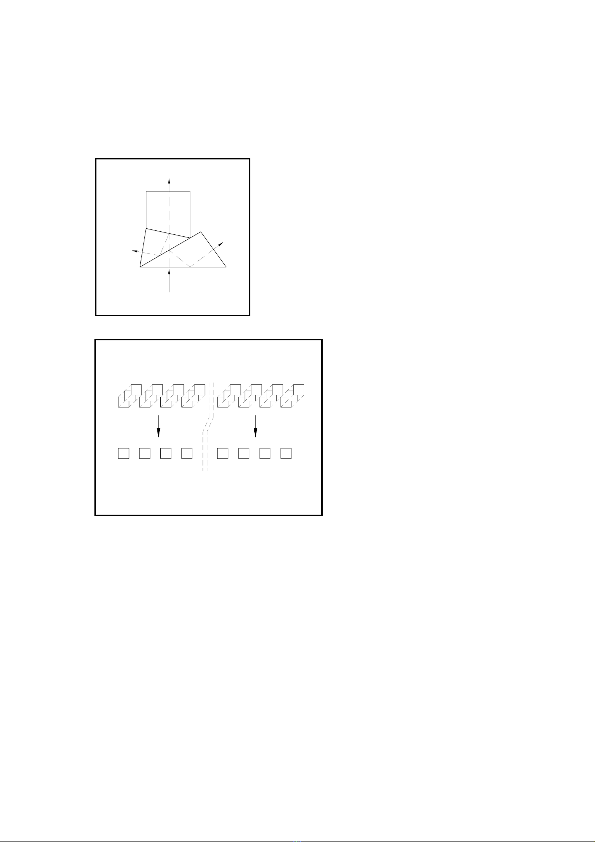
3.1 COLOUR SEPARATION ................................................................................................... 8
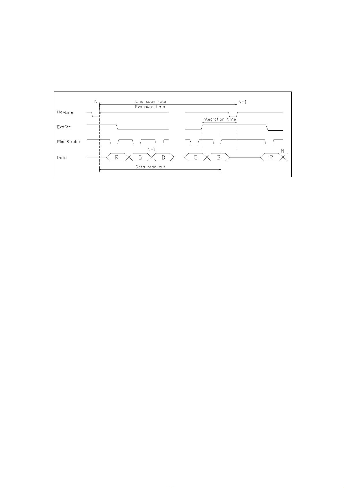
3.2 CAMERA OPERATION..................................................................................................... 8
4. PROCESSING OF CCD OUTPUT...............................................................................11
4.1 ANALOGUE VIDEO PATH ............................................................................................... 11
4.2 PIXEL CORRECTION UNIT.............................................................................................. 12
4.2.1 Description.........................................................................................................12
4.2.2 Data order..........................................................................................................12
4.2.3 Correction algorithm..........................................................................................12
4.2.4 Implementation of the correction.......................................................................14
5. CAMERA INTERFACE................................................................................................16
5.1 POWER INPUT ............................................................................................................. 16
5.2 LED INDICATORS ........................................................................................................ 17
5.3 DATA CONNECTOR ...................................................................................................... 18
5.4 RS-232 PORT ............................................................................................................. 19
5.5 PROGRAMMING CONNECTOR........................................................................................ 19
6. MECHANICAL STRUCTURE......................................................................................20
6.1 MECHANICAL DIMENSIONS AND MOUNTING OF THE CAMERA ........................................... 20
6.2 ATTACHMENT FOR OPTICS ........................................................................................... 20
7. OPTICAL CONSIDERATIONS....................................................................................21
7.1 SPECTRAL RESPONSE ................................................................................................. 21
7.2 SELECTION OF OPTICS ................................................................................................. 22
7.2.1 Modulation transfer function..............................................................................22
7.2.2 Resolution and field of view...............................................................................23
7.2.3 Depth of field and working aperture ..................................................................23
8. LIGHTING ....................................................................................................................25
8.1 SPECTRAL RADIANCE AND COLOUR TEMPERATURE ........................................................ 25
8.2 UNIFORMITY OF LIGHTING ............................................................................................ 25
9. TECHNICAL SPECIFICATIONS .................................................................................27
10. APPENDIXES ..............................................................................................................28
10.1 APPENDIX A: CAMERA LINK®OUTPUT BIT PORT ASSIGNMENTS ................................ 29
10.2 APPENDIX B: TIMING DIAGRAMS ........................................................................ 30
10.2.1 B1: Parallel colour channels output modes.......................................................30
10.2.2 B2: Multiplexed colour channels output modes.................................................31
10.3 APPENDIX C: SERIAL COMMUNICATIONS ............................................................ 32
10.4 APPENDIX D: MODEL NUMBERS FOR XIIMUS CAMERAS ..................................... 50
10.5 APPENDIX E: ORDERING CODES FOR XIIMUS CAMERAS..................................... 51
10.6 APPENDIX F: APPLICATION NOTES ..................................................................... 53
10.6.1 TVI-AN701: Using encoder Inputs for triggering...............................................53
10.7 APPENDIX G: COOLING OPTION ......................................................................... 55
© TVI Vision, 14 July 2006 page 4 ( 56 )

XIIMUS 4K CL User Manual. Model: 4096CT. Version 1.4
1. INTRODUCTION
The XIIMUS is a series of rugged, high performance, fully digital colour line scan camera for
demanding industrial applications. It utilises a high accuracy 3-CCD architecture with a
choice of either 512, 1024, 2048 or 4096 pixel sensors at speeds up to 40 million pixels per
second per colour channel. The TVI Vision XIIMUS cameras are optimised for high sensitivity
and precise colour recognition.
The applications for the XIIMUS cameras include:
• web inspection
• inspection of natural materials like food, wood, ore, minerals and lumber
• recycling
• quality control in printing processes
• texture recognition
CUSTOMER SUPPORT
If you need to contact the manufacturer directly, please send your questions preferably by
email to TVI Vision. They will be forwarded to the responsible persons, who will contact you
as soon as possible.
E-mail: [email protected]
Fax: +358 9 7590 0319
Phone: +358 9 759 001
Address: Asentajankatu 3
00880 Helsinki
FINLAND
© TVI Vision, 14 July 2006 page 5 ( 56 )

XIIMUS 4K CL User Manual. Model: 4096CT. Version 1.4
2. PRECAUTIONS
Read the manual
Please read the manual carefully before using the camera the first time.
Do not drop the camera
Handle the camera with care at all times, since it is a sensitive optical device. Do not drop the
camera and avoid mechanical shocks to the camera.
Keep foreign matter outside the camera
Do not spill liquids on the camera. The camera is not liquid or waterproof.
Do not drop any kind of objects or foreign material into the camera. Metallic objects might
cause short circuit and/or damage the optical assembly.
Cleaning
Keep the shade cap on the camera head when not used to avoid contaminating the prism.
The input surface of the prism is not shielded nor protected from the outside of the camera.
It is recommended that the camera is serviced by TVI Vision, if the front surface of the prism
is very dirty, since the surface area of the prism cannot be fully accessed from the front.
If there are small amounts of contaminants or dust on the prism surface, use a clean lint free
cotton swab or other non-abrasive medium dipped in acetone or pure alcohol to clean prism
surface. Shake excess solvent off before touching the surface of the prism to avoid streaking.
TVI Vision is not responsible for any scratches or damage inflicted by the customer to the
front surface of the prism.
To clean the exterior casing of the camera, use a soft, dry cloth. In case of severe stains use
a small amount of pure alcohol. Do not use isopropyl alcohol or acetone or other volatile sol-
vents such as benzene or thinners.
Do not open the camera
Do not open the camera. In doing so, the warranty of the camera will expire immediately.
Only authorised service personnel may open the camera.
Ventilation
Allow sufficient air circulation around the camera. If this condition is not met the camera might
shut down during operation, because it is designed to do so in order to prevent damage to
the optical assemblies. Further increase of the temperature may damage the camera.
© TVI Vision, 14 July 2006 page 6 ( 56 )

XIIMUS 4K CL User Manual. Model: 4096CT. Version 1.4
Storage
Do not store the camera in a temperature over +55 ºC or 131 F. There is a permanent tem-
perature indicator inside the camera, which is installed to ensure that if the camera is
damaged due to overheat, the warranty of the camera may be void.
Electromagnetic fields
Do not operate the camera in the vicinity of strong electromagnetic fields (above the require-
ments of CE conformity). This may cause erroneous operation of the camera.
Transporting
Preferably transport the camera in its original packaging. If the package is discarded, please
package with care in thick layer of soft, preferably anti-static material when transporting. Do
not use material that allows the camera to drop to the bottom of the package while trans-
porting. Do not transport with an objective attached.
© TVI Vision, 14 July 2006 page 7 ( 56 )

XIIMUS 4K CL User Manual. Model: 4096CT. Version 1.4
3. CAMERA OVERVIEW
3.1 Colour Separation
The incoming light is separated into three, Red,
Green and Blue, colour images by an RGB beam
splitter (figure 3.1). The spectral distribution of each
colour is standardised and well known. By attaching
a CCD to each of these colour outputs, it is possible
to measure the intensity of each colour image.
BLUE
GREEN
RED
INCOMING LIGHT
Figure 3.1 The RGB colour separation beam splitter.
The CCDs are aligned to each other
to get the perfect image of the three
measured colour components. All
the three CCDs see exactly the
same area of the target from same
viewing angle, distance and at the
same time. Corresponding pixels of
all the three sensors are very
precisely positioned optically in the
same place. This makes the colour
analysis simpler and does not
require any line matching or
synchronising of separate colour
lines. The resolution of the camera
is the same as for the individual
CCD array.
R
G
B
RGB color line
3 x CCD
Figure 3.2. Alignment of the CCD linear arrays.
3.2 Camera Operation
The CCDs convert incoming light into electrical charge. The amount of charge generated in
each of the individual pixels is directly proportional to the intensity of light they receive. The
resulting charge packets are transferred into two high-speed CCD shift registers and trans-
ferred to the output charge-to-voltage converters of the CCDs. The generated output video is
Correlate Double Sampled (CDS) and amplified by two user accessible gain factors prior to
digitisation into 12 bits.
© TVI Vision, 14 July 2006 page 8 ( 56 )

XIIMUS 4K CL User Manual. Model: 4096CT. Version 1.4
CTRL
DCDC
Vin
OSC
Ctrl out
voltage
monitoring
temperature
monitoring
TIMING
GAIN CTRL
AD12 bits
Data out
Ctrl in
AD
12 bits
AD12 bits
AD12 bits
AD
12 bits
AD12 bits
CCD
CDS
CDS
CCD
CDS
CDS
CCD
CDS
CDS
PCU
N
on volatil
e
memory
RS
232 2
2
Figure 3.3. The block diagram of the camera.
The XIIMUS cameras operate in a mono-shot mode. For each rising edge of the NewLine
signal the camera responds by sending out the digital data stream of the previous line scan
period time. The output frequency is constant. The distance in time between two NewLine
edges can be set to any value above the specified minimum. The reciprocal of this time is the
line rate (Hz).
The XIIMUS cameras have been optimised for high-speed applications. Therefore best per-
formance is achieved at line rates of hundreds of lines per second or above.
Line 1 Line 3
Line 0 Line 1 Line 2 Line 3
Data out
NewLine
Line 2
Line scan rate
( CC1 )
Figure 3.4. The relation of the data output and NewLine signals.
© TVI Vision, 14 July 2006 page 9 ( 56 )

XIIMUS 4K CL User Manual. Model: 4096CT. Version 1.4
The effective integration time can be made shorter than the actual exposure time (time bet-
ween two consequent NewLine (CC1) pulses, Line scan period) by holding the ExpCtrl (CC2)
signal in its active stage until the beginning of the targeted interception period. Within the
exposure time, whenever the ExpCtrl input is held low, no charge can be collected into the
pixels. This is why the actual integration time is the distance in time of the (last) rising edge of
the ExpCtrl input signal and the next rising edge of the NewLine input.
Figure 3.5. The line rate and the integration time (data is drawn for muxed output mode).
The two most common operation modes of line scan cameras are free-run mode or encoder
input driven mode.
In the free run mode both the line rate and the integration time can be precisely controlled.
But if the line rate is determined by encoder input, the integration time can best be kept
constant by using the encoder input pulse for generating the ExpCtrl signal. The NewLine
pulse is sent after a constant delay (appendix F).
The XIIMUS camera is constantly monitoring all the internal supply voltages and the internal
temperature of the camera. Temperature warnings can be monitored via the LEDs of the rear
panel or by reading the status via serial communications.
Other functions include:
•colour channel specific programmable exposure control
•colour channel specific programmable analogue gain
•colour channel specific programmable digital gain
•programmable offset
•retrieval of the firmware version and serial numbers
•non-volatile memory banks for the programmable settings
•user programmable pixel correction unit
•test pattern generation for interfacing
•self-clocking mode for operation at fixed line rate without line request input
© TVI Vision, 14 July 2006 page 10 ( 56 )

XIIMUS 4K CL User Manual. Model: 4096CT. Version 1.4
4. PROCESSING OF CCD OUTPUT
4.1 Analogue video path
TVI XIIMUS cameras utilise a two channel CDD for each colour. A simplified illustration of the
analogue video path of one channel is in figure 4.1.The video path itself is completely ana-
logue until digitised with 12-bit resolution in close vicinity of the CCD itself. All adjustments
performed on the analogue video signal are digitally controlled.
Figure 4.1. Analogue video path
The analogue video signal is first Correlate Double Sampled and amplified in the preamp
gain stage. After the CDS block it is possible to further amplify the signal with an analogue
gain stage.
The analogue video path also includes an input clamp circuit that is not drawn in the illustra-
tion. The input clamp circuit removes the CCD’s optical black offset to maximise system
headroom and the effect of gain change on the black level. The effect of this circuit causes
the digital output data to start from zero when the CCD is exposed to dark. If desired, the
dark level register can be used to set a positive offset in the output data. If this parameter
differs from zero, the dark level of channel in question will have an offset equal to the dark
level setting. Changing this setting can be desirable when using the pixel correction unit,
since the pixel to pixel variations in dark will be present in the raw data enabling better cor-
rection.
Lastly the 12-bit data streams from the two output channels are digitally multiplexed into one
data stream to represent the CCD output.
© TVI Vision, 14 July 2006 page 11 ( 56 )

XIIMUS 4K CL User Manual. Model: 4096CT. Version 1.4
4.2 Pixel correction unit
4.2.1 Description
The TVI XIIMUS series line scan cameras incorporate a user programmable real time pixel
correction unit, PCU. The PCU can be set up by downloading appropriate correction data via
the serial port to the camera.
The PCU can simultaneously perform white balancing, removal of pixel to pixel offsets
(PRNU & DSNU), lighting profile correction, removal of lens curvature and/or perform custom
operations on the output data of the camera.
4.2.2 Data order
The correction data consist of 24 bits of data per colour pixel. Thus, for a full RGB-pixel the
user has to provide 72 bits of data. The data is sent to the camera via the RS-232 port
(Camera Link or separate 9-pin D-connector) starting with the first pixel in the line. Colours
are sent in RGB order to the camera. The start of the transmission to the camera is illustrated
below, each letter corresponds to one byte (8 bits) of data:
1 2 3
RRR GGG BBB RRR GGG BBB R..
Within a single colour pixel the data is ordered into a multiplier and an offset. The multiplier
consists of 14 bits and the offset of 10 bits. Thus, the three bytes that make up the correction
data for one colour pixel are internally divided on a bitwise level as follows:
R (byte 0) R (byte 1) R (byte 2)
Multiplier Offset
13
12
11
10
9
8
7
6
5
4
3
2
1
0
9
8
7
6
5
4
3
2
1
0
Please refer to the serial communication section of this document for additional information
on how to download correction data to the camera.
4.2.3 Correction algorithm
The pixel correction unit (PCU) utilises a simple linear algorithm to correct the digital output
data of the camera. The formula below is used to correct all data once correction is enabled:
yi = (xi- bi) xai
yi= corrected output data
xi= camera raw data
bi= offset to be subtracted from the raw data
ai= multiplier for scaling of data
Since the offset bihas a 10-bit range, it is possible to subtract greater values than the
camera dark level, which is typically around 40 DU. As an example, the user might want to
subtract the background of the image instead of the dark level.
© TVI Vision, 14 July 2006 page 12 ( 56 )

XIIMUS 4K CL User Manual. Model: 4096CT. Version 1.4
Figure 4.2. Correction algorithm.
The multiplier aihas a 14-bit range. The multiplier is scaled so that a 14-bit multiplier value of
4096 DU by default equals multiplying by one. So, in order to increase the signal of a pixel it
has to be multiplied with a number greater than 4096 DU and accordingly it has to multiplied
with a smaller number to attenuate the signal. This means that a single pixel cannot be mul-
tiplied with a multiplier greater than 4 or attenuated more than into 1 / 4096. Please note that
multiplying with a number that is larger than one (4096) will result in some more noise in the
image, because the original data is scaled up (“stretched”) to cover a larger range.
By altering the content of the shifter register, it is possible to reset the multiplier unity level to
any power of two between 128 and 16384. Please notice, that setting this register to 16384
will not permit any amplification, but on the other hand will permit fine resolution attenuation.
Also, setting this register to low values will permit much amplification, but will make the mul-
tiplier effect coarser at values close to the selected unity value.
As mentioned above, the correction unit can perform multiple corrections on the image with
one set of correction data. White balancing or any user defined colour balance can be
achieved by multiplying the colour channels that have a response differing from the desired
response with suitable multipliers.
© TVI Vision, 14 July 2006 page 13 ( 56 )

XIIMUS 4K CL User Manual. Model: 4096CT. Version 1.4
4.2.4 Implementation of the correction
Figure 4.3. Block diagram of the correction data path.
The correction algorithm is implemented as illustrated above for each colour channel. Firstly,
all offsets are subtracted from the raw 12-bit CCD output data. This includes the pixel to pixel
offsets in the dark (DSNU) and any custom subtractions. In the diagram this subtraction is
marked as SUBi. Also, the colour channel specific offset is subtracted from the raw data.
Thus, altogether it is possible to subtract half of the camera dynamic range from the raw
data.
Secondly, after performing the subtractions, the data is multiplied with a 14-bit pixel specific
multiplier. This will result in a maximum of 26 bits of data per pixel, out of which, the topmost
12-bits are routed to the data output of the camera. The output data passes through a left
shifter where it is possible to digitally amplify the data by shifting it zero to seven positions to
the left. Also, the shifter will shift the data to the correct location depending on the unity mul-
tiplier level set in the shifter register.
Example:
The shifter register is set to 7, which equals 128 as a unity multiplier. The digital gains are set
to 7 as well, which equals 128x digital gain. In this case, the result after the multiplication is
shifted up 14 positions which means the lowest 12-bits of the resulting 26-bits are shifted to
the data output.
Example on performing multiple corrections
White balancing can be achieved by selecting the multipliers so that the data values on all
colour channels are equal in digital response from pixel to pixel. Normally, the channel that is
closest to saturation is selected as a reference where the other channels are corrected.
Other choices are possible but they limit the dynamic range of the output signal. The image
below depicts a typical situation. In the image, the output of the red channel is where the
other two channels are corrected. Now, to achieve white balance, the red channel line has to
be multiplied with a constant one for every pixel in the line and the green and blue channel
pixels with multipliers of little over one varying from pixel to pixel, so that each colour pixel will
have a balance of its own.
© TVI Vision, 14 July 2006 page 14 ( 56 )

XIIMUS 4K CL User Manual. Model: 4096CT. Version 1.4
In order to remove unevenness of the lighting profile and lens curvature along the vector at
the same time as when performing white balancing, each individual pixel along the vector
needs to be scaled to the corresponding red maximum value (L1). Now, in this case, in order
for the line profile on all colour channels to equal line L1, the red channel line also has to be
scaled. Thus, at the beginning of the red line, the lowest pixel value at level L2 has to be mul-
tiplied with a multiplier Rx, so that it equals line L1. Accordingly, at the start of blue channel
line, the line L3 has to match line L1 for the camera to be in white balance.
As illustrated in fig. 4.4, the blue channel will have the largest multipliers and the centre of the
red channel line will have multipliers close to unity. Also, the far ends of each colour channel
will have the largest multipliers of the colour channel in question.
Fi
g
ure 4.4. Correction in the direction of the vector.
© TVI Vision, 14 July 2006 page 15 ( 56 )

XIIMUS 4K CL User Manual. Model: 4096CT. Version 1.4
5. CAMERA INTERFACE
All the electrical connections of the XIIMUS colour line scan camera are made via the rear
panel.
The DC power is input via the 2-wire, shielded power cable (included in the delivery). The
cable side connector should be pushed and pulled by holding on to the sleeve at the central
part. It must never be turned or pulled by holding on to the rear part of the connector or the
cable itself.
The two Camera Link® connectors are used for interfacing to commercial Camera Link frame
grabber boards or users' own electronics.
All signals are available on the two
Camera Link connectors. The interface
is designed according to Camera Link
specification v1.1.
Standard RS-232 interface is used for
modifying the parameters of the
camera. The serial port interface is
also available on the first Camera Link
connector according to the specifica-
tions. The port is set according to the
order. Ask for detailed instructions, if
you want to swap it later on.
Six indicator LEDs (on the right hand
side) show the status of the camera.
Figure 5.1. The rear panel layout for Camera Link®models.
5.1 Power input
The connector is labelled as ‘PWR IN’. A power cable is included in all the camera ship-
ments. The bottom most pin of the cable represents the positive supply voltage and the top-
most is the respective zero volts. The mating power connector part number is: odu S21L0C-
T02LPH0-6200. The recommended cable bend relief can be ordered with p/n code: odu
701.022.208.960.050.
The XIIMUS cameras operate from a single supply voltage of nominally +24 VDC at typically
500 to 1000 mA depending on the operation mode and the external terminations of the output
signals.
The maximum power consumption is 26 W. For low frequency line ripples (less than 120 Hz)
±10 % of ripple is acceptable as long as the voltage level stays between +20 to +36 VDC.
© TVI Vision, 14 July 2006 page 16 ( 56 )

XIIMUS 4K CL User Manual. Model: 4096CT. Version 1.4
Supply voltage:
Nominal: +24 VDC
Range: +20 to +36 VDC
Supply current:
Typically: 500 to 1000 mA
Maximum: 1.1 A (at +24 VDC and at power-up only)
Ripple:
±10 % (max 120 Hz)
- voltage level (=nominal + ripple) must stay
between +20 to +36 V
5.2 LED indicators
From top downwards the LEDs are as follows:
POWER, green
ON: power input OK
RUN, green
ON: normal operation
OFF: ¹ The higher temperature limit has been exceeded and the
camera operation has been shut down. After the external tem-
perature has fallen into the specified range, switch the power
once OFF and then ON again.
² The camera did not start up properly. Check the input power
lines and the POWER LED. The power supply must be able to
supply enough current quickly at beginning of the power-up.
STATUS 1, green
ON: Correction unit (PCU) is enabled
OFF: Correction unit (PCU) is disabled
STATUS 2, green
ON: Camera is ready for operation with correction data loaded.
OFF: Camera is performing internal boot cycle
PWR ERROR, red
ON: at least one of the internal supply voltages has failed
© TVI Vision, 14 July 2006 page 17 ( 56 )

XIIMUS 4K CL User Manual. Model: 4096CT. Version 1.4
TEMP ERR, red
ON: Warning of too high an internal temperature. If the camera cools
down, this warning will be removed, but if the temperature rises
further the camera will be stopped permanently until the next
power-up. Please note that this is only an early warning of high
operating temperature and that it is permitted to use the camera
even when this warning is continuously on. The status of
temperature monitoring can be read via serial communications.
5.3 Data Connector
Two MDR-26 connectors handle the data communication according to the Camera Link
specification. The connectors are labelled CL1 and CL2. CL1 is for Base Configuration. Both
connectors are needed for Medium and so called Dual Base (non-standard) Configurations.
Cables can be secured with either screw locks or latches.
All signals are specified by the Camera Link standard, except the four Camera Control inputs:
CC1 NewLine
- the rising edge defines the change-of-line moment (after a constant delay)
- period is the line rate
CC2 Exposure Control Red (or all channels)
- exposure control signal for the Red channel
- the effect for this is defined by the mode that is selected via
RS-232 interface or Camera Link serial port
- as default this signal is common to all the three CCDs
- a low level resets all the pixels
- should be constantly high, if full time exposure is needed
- a constant '0' results in dark images
CC3 Exposure Control Green
- exposure control signal for the Green channel when camera is set to
individual exposure control mode
CC4 Exposure Control Blue
- exposure control signal for the Blue channel when camera is set to
individual exposure control mode
For cabling please refer to the Camera Link specifications. TVI Vision also provides Camera
All the input signals are internally terminated by 100 Ωresistors.
All the output signals should be terminated respectively (one 100 Ωresistor connected
between the positive and negative wire of each signal pair).
Appendix A shows the output bit port assignments of all the available Camera Link modes.
Appendix B presents the timing details of the interface signals.
© TVI Vision, 14 July 2006 page 18 ( 56 )

XIIMUS 4K CL User Manual. Model: 4096CT. Version 1.4
5.4 RS-232 port
The RS-232 connector is used for changing the settings of the camera and for
communicating with the internal micro controller. Please, refer to the Appendix C for detailed
description on wiring and the communication protocol. The same functions are alternatively
available via Camera Link.
The advantages of this separate port are faster operations due to hardware handshaking and
independence of the image grabbing. TVI Vision provides free software with source codes for
both options. Please specify the port, when ordering cameras.
The connector is a standard 9-pin, plug type connector with the following pin-out as seen
from the behind of the camera:
Figure 5.2. The pin numbers of the RS-232 plug connector.
Table 5.1. Pin-out of the RS-232 connector
PIN NAME DIRECTION DESCRIPTION
1 -
2 RD input Receive Data
3 TD output Transmit data
4 -
5 SG - Signal Ground
6 -
7 RTS output Request To Send
8 CTS input Clear To Send
9 -
5.5 Programming connector
The 15-pin D-shell connector on the left side of the back plane is reserved for factory use.
New firmware updates can also be downloaded using this connector. Ask TVI Vision for
detailed procedure, before removing the cover of the connector.
© TVI Vision, 14 July 2006 page 19 ( 56 )

XIIMUS 4K CL User Manual. Model: 4096CT. Version 1.4
6. MECHANICAL STRUCTURE
6.1 Mechanical dimensions and mounting of the camera
The mechanical structure of the camera provides a compact entity to meet the rigid de-
mands of the industrial environment. The camera case is aluminium, which provides an
excellent electrical protection against external electromagnetic interference. When selecting
the components, corrosion resistance has also been considered.
The camera can be mounted from the front panel or from the side panel of the camera. The
recommended way to mount the camera is to use the three M5 holes, which are situated
around the optics on the front panel.
There are three possibilities to mount the camera with the mounting holes at the side of the
camera body. First possibility is to fasten the camera with four screws to a special mounting
stand. The second option is to use a normal camera tripod, using a standardised tripod at-
tachment 1/4", 20 UNF. The third is to use two M6 threaded holes to attach the camera to
any application specific frame or support.
Figure 6.1. Dimensional drawing of 4096CT camera.
6.2 Attachment for optics
There is a locking latch in the Nikon bayonet. The optics are attached by turning it (ca. 1/4
rev.) counter clockwise, viewing from the front of the camera, until the latch rises into the
upper position. When detaching the optics, push the latch first towards the front panel of the
camera and then turn the optics clockwise, again viewing from the front of the camera, until
the optics are released from the bayonet. The optics may then be pulled away from the
camera.
© TVI Vision, 14 July 2006 page 20 ( 56 )
Table of contents
Popular Digital Camera manuals by other brands

Samsung
Samsung MV900F Manual Del Usuario

Conrad
Conrad 75 41 09 operating instructions

Minolta
Minolta DIMAGE EX instruction manual

Digital Watchdog
Digital Watchdog MegaPix Pano DWC-PVF5M1TIRC6 quick start guide

Samsung
Samsung DIGIMAX I6 Product information & user guide

Olympus
Olympus Camedia D-340R quick start guide

GE
GE C1440W Manual de usuario

ZEISS IKON
ZEISS IKON CONTAFLEX II Instructions for use

Concord Camera
Concord Camera Eye-Q 3103 Frequently asked questions

Zeiss
Zeiss Axiocam 105 color Installation & reference manual

Olympus
Olympus Digital Vision D-340L instructions

Olympus
Olympus FE-26 - Digital Camera - Compact instruction manual