1
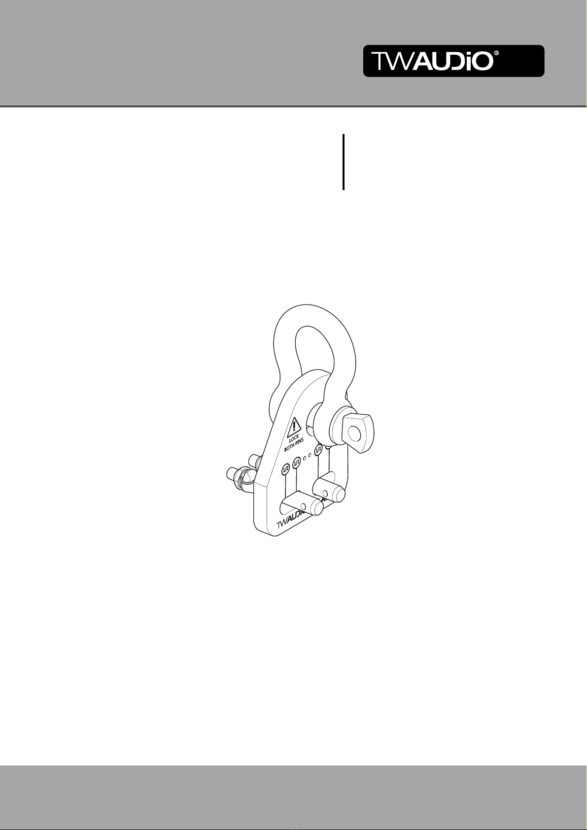
Assembly Manual for VERA LA900
1. Safety | Intended use
Please adhere to the following safety instructions to avoid risks when operating the ac-
cessory parts.
The VERA LA900 load adapter (with shackle) was developed for professional use in
sound systems.
TW AUDiO GmbH shall not be held liable for any damage that ensues from unintended
use.
WARNING
Before each installation, check the VERA LA900 load adapter for its completeness and
the proper condition of all parts.
WARNING
The VERA LA900 load adapter must only be used with products of the VERA20 and
VERA36 series.
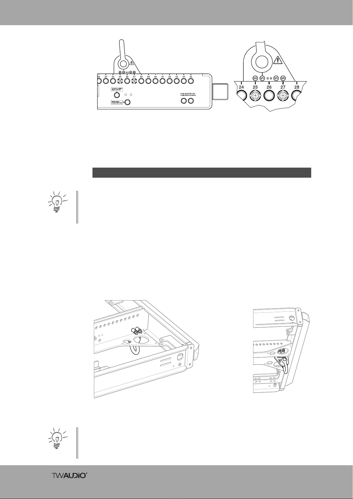
This installation manual describes the way the VERA LA900 load adapter may be used.
Any other use is deemed improper. This can lead to material damage and even personal
injury.
Modifications or conversions to the individual parts of the VERA LA900 load adapter are
not permitted. Danger to life!
CAUTION
The VERA LA900 load adapter is designed for use indoors and outdoors.
WARNING
The VERA LA900 load adapter may only be used by trained and qualified personnel.
The load adapter must be checked for complete suitability before each use of the
VERA LA900.
WARNING
The VERA LA900 load adapter must be taken immediately out of operation as soon as
any visible damage is detected on the parts.
WARNING
The fastening points, such as ceilings, trusses, etc. must be fully checked for load ca-
pacity and stability before installing the VERA LA900 load adapter.
The VERA LA900 load adapter is designed for a load of 1.5 to [3307 lb] (BGV-C1).
This load capacity must never be exceeded!
WARNING
Check the screw connection at every installation of the VERA LA900 load
adapter.Tighten if loose. If this is not possible, replace the fasteners.