Twilight PTZPRO27 User manual

INSTRUCTION MANUAL
Please read this manual throughly before use and keep it handy for future reference
700TV High Speed Dome Camera
User Manual

WARNINGS and CAUTIONS
EXPLANATION OF GRAPHICAL SYMBOLS
TO REDUCE THE RISK OF ELECTRIC SHOCK, DO NOT REMOVE COVER(OR BACK).
NO USER-SERVICEABLE PARTS INSIDE. REFER SERVICING TO QUALIFIED SERVICE PERSONNEL.
RISK OF ELECTRIC SHOCK
DO NOT OPEN
2
WARNINGS
TO REDUCE THE RISK OF FIRE OR ELECTRIC SHOCK.
DO NOT EXPOSE THIS PRODUCT TO RAIN OR MOISTURE.
DO NOT INSERT ANY MEALMETALLIC OBJECTS THROUGH THE VENTILATION GRILLS OR OTHERS
OPENINGS ON THE EQUIPMENT.
The lighting ash with arrowhead symbol, within a triangle, is intended to alert the user
to the presence of un insulated dangerous voltage within the product enclosure that
may be of sucient magnitude to constitute a risk of electric shock to persons.
The exclamation point within an equilateral triangle is intended to alert the user to the
presence of important operating and maintenance (servicing) instruction in the literature
accompanying the product.
CAUTIONS
CE COMPLIANCE STATEMENT
FCC INFORMATION : THIS EQUIPMENT HAS BEEN TESTED AND FOUND TO COMPLY WITH THE LIMITS FOR A CLASS A DIGITAL
DEVICE, PURSUANT TO PART 15 OF THE FCC RULES. THESE LIMITS ARE DESIGNED TO PROVIDE REASONABLE PROTECTION
AGAINST HARMFUL INTERFERENCE WHEN THE EQUIPMENT IS OPERATED IN A COMMERCIAL ENVIRONMENT.
THIS EQUIPMENT GENERATES, USES, AND CAN RADIATE RADIO FREQUENCY ENERGY AND IF NOT INSTALLED AND USED IN
ACCORDANCE WITH THE INSTRUCTION MANUAL, MAY CAUSE HAARMFUL INTERFERENCE TO RADIO COMMUNICATIONS.
OPERATION OF THIS EQUIPMENT IN A RESIDENTIAL AREA IS LIKELY TO CAUSE HARMFUL INTERFERENCE IN WHICH CASE THE
USER WILL BE REQUIRED TO CORRECT THE INTERFERENCE AT HIS OWN EXPENSE.
CAUTION : CHANGES OR MODIFICATIONS NOT EXPRESSLY APPROVED BY THE PARTY RESPONSIBLE FOR
COMPLIANCE COULD VOID THE USER’S AUTHOURITY TO OPERATE THE EQUIPMENT.
THIS CLASS A DIGITAL APPARATUS COMPLIES WITH CANADIAN ICES-003.
CET APPAREIL NUMERIQUE DE LA CLASSE A EST CONFORME A LA NORME NMB-003 DU CANADA.
WARNING
THIS IS A CLASS A PRODUCT. IN A DOMESTIC ENVIRONMENT THIS PRODUCT MAY CAUSE RADIO
INTERFERENCE IN WHICH CASE THE USER MAY BE REQUIRED TO TAKE ADEQUATE MEASURES.
COMPLIANCE STATEMENT

IMPORTANT SAFEGUARDS
3
Read all of the safety and operating
instructions beforeusing the product.
Keep the temperature from
-50˚C to 50˚C
IP67 (Waterproof )
That avoid ammability material, or oil. Do not avoid the installation
from electrical supplied pole.
If the camera have some problem,
please stop the operating.
Do not attempt to disassemble
the appliance.
Always use the recommended power. Do not pull the cable.
Never touch un-insulated
parts with wet hands.
Do not use the appliance where
there is excessive dust smoke or moisture.
Please install the product on a
completely at oor.
Manual
High Speed Dome
with IP 67 rated outdoor housing is specially unique & creative designed for strong durability & extremely
reliability.
This camera oers perfect prevention of dew condensation and clear image at operating temperature from -50℃~ 50℃.
Especially, this mechanism supports
greatly increase accuracy and decreasing operation noise. With an accuracy position,
it can
precisely maintain preset camera positions even after frequent panning and tilting. Also, it oers
perfect control of
camera mechanism speeds even at high 37x magnication the camera can quickly and accurately capture images from
360°/sec to 0.1°/sec at the slowest creep speed.
Precautions for proper Operation
*
Do not install the unit a place subject to direct sunlight, excessive moisture, dust or vibrations where ventilation is poor.
* Please use the unit in the range of a guarantee temperature and humidity of operation.
* Please set ID of a camera as the same number as the input channel to DVR or Matrix switcher.
DC12V/AC24V

TABLE OF CONTENTS
4
- WARNINGS AND CAUTIONS
- IMPORTANT SAFEGUARDS
- TABLE of CONTENTS
- PACAGE CONTENTS
- INSTALLATION & CONFIGURATION
-- Addres switch setting
-- Wall Mount Installation
-- Ceiling Mount Installation
-- Interface Cable Wiring
- DIMENSION
- SPECIFICATION
- OPERATION & PROGRAMMING
-- Menu Tree
-- Check point & Programming
-- System : Information
Reboot
Factory
Event Log
Password
-- Dispaly : OSD Setup
Area Title
Privacy Zone
Image Setup
-- Dome : General
Motion
Home
Preset
Tour
Pattern
Scan
-- Camera : Focus / Zoom
White Balance
Exposure
Advanced Setup
Reset
-- Alarm
2
3
4
5
6
7
8
9
9
10
10
11
12
12
12
13
13
13
14
14
14
15
15
16
16
16
17
17
18
18
19
19
19
20

PACKAGE CONTENS
5
1. Dome camera Unit
2. Body (W/O Sunshield)
3. Trimring Bubble Dome
4. Wrench-3mm
5. User’s manual
Option Bracket
The following parts are supplied with the speed dome system.
Wall Bracket Ceiling Bracket
Dome Camera Unit Bubble Dome Ass’y Housing Body (W/O Sunshield) Sunshield (Option) WrenchManual
1
1
1
1
1
Precautions
-
The following steps of installation and connection work should be done by qualied service personal
or system installers and should conform to all local codes.
- Be sure to switch the camera o before installation and connection.
- Do not install the camera beside air outlet of an air conditioner.
STEP 4.
- Remove the airbag
- Open the screw for dome camera unit.
- Take out the dome camera unit from
housing body ass’y
STEP 1. STEP 2.
STEP 3.
- Screw open the bubble
Airbag

INSTALLTION
6
Each Part Name
1 Pin description
2 Dip switch for protocol and baud rate
3 Address switch
DC Only
①
②
③
Dome Camera Unit Rear View
DC Only
Address Switch Setting
- Before installation, please set the address switch as described in this manual.
(You have to set the “Address switch” as you want before installation.)
Default (0,1)
<Table A. Protocols >
<Table B. Baud rate >
- Default baud rate is 2400bps. See table B for details.
<Table C. Termination >
- See table C for details.
Switch1 Switch 2 Protocols
O O Pelco-D , Pelco-P, etc. Auto detect.
Switch3 Switch 4 Baud Rate (bps)
O O 2400 * default
O On 4800
On O 9600
On On 38400
Switch5 Termination
O Not Terminated (default)
On Terminated
Protocols Setting
- If you are going to use pelco-D, pelco-P protocols to communicate
with the dome system, you do not have to set any switches.
The unit automatically detects these protocols. See table A for details.
DC Only
Termination Free
-
When the camera is installed, the last cmaera does not necessary for termination process.
- If you set the switch “Termiation ON” for last camera, you can have easy installation.

INSTALLTION
7
Wall Mount Bracket - Camera Set Assemble
STEP 1.
Connect the dome camera unit to housing body Ass’y.
(Turn the 4ea of each screw to the right)
①Alarm cable connection
②RJ45 jack connection
③Heater terminal connection
STEP 2.
Remove the holder screw.
STEP 3.
When you assemble the dome bubble Ass’y,
Please follow up the picture.
STEP 4.
Connect the dome bubble Ass’y
to the housing body Ass’y.
Wall Mount Installation
①
②
STEP 1. Fix the TP 18 x 30L Screw supplied.
NO Parts Name DESCRIPTION Q’ty
2 Monut Screw TP1 8 x 30L 4
1 Wall Mount Bracket AL Diecasting 1
STEP 2.
Pass the cables through the bottom of the bracket.
STEP 3.
Hang the safety hook against drop on the bracket.
STEP 4.
Put the dome cable into the bracket and x it.

INSTALLTION
8
Wall Mount Installation
STEP 5.
Fix the camera set by used screw as the picture.
STEP 6.
Assemble the xed screws using the wrench supplied.
STEP 7.
Connect the camera cable to the bracket cable.
Please see the cable connection.
STEP 8.
Close the bracket cover and x it by knob bolt.
Fix the steel cover supplied on the upper of the bracket
using screw CM3x8L.
Ceiling Mount Installation
STEP 1.
Fix the plastic anchors on the ceiling as
this gure and x the ceiling using the
screws supplied.
STEP 2.
Fix the pipe supplied as this gure turning it clockwise.
STEP 3.
Connect the camera and the bracket cable and x it turning the camera set clockwise.
STEP 4.
Assemble the xed screws using the wrench supplied.

INSTALLTION
9
DIMENSION
Each Part Name - Cable connection
①Interface cable RJ45
Alarm IN
Alarm IN
Alarm IN
Alarm IN
Alarm OUT
Alarm OUT
Alarm OUT
GND
GND
Control
Control
Black / White
Black
Orange
Green
Brown / White
Red / White
Orange / Black
Brown
Yellow / Black
Green / White
Blue / White
Alarm 0
Alarm 1
Alarm 2
Alram 3
NO
COM
NC
GND
GND
RS-485 -
RS-485 +
1
2
3
4
5
6
7
8
9
10
11
233.0
110.0
300.9
300.9
16.0 16.0
261.0 261.0
322.3
322.3
211.3
211.3
471.6
279.3
471.6
279.3
170.0
277.3
235.0
233.0
TINT
COLOR
BRIGHT
CONT.
V1
VOLUMEUNDER
SCAN
S-VIDEO
POWER
V2
PMC14H
Video
Power

SPECIFICATION & MENU TREE
10
Camera
Image Sensor
Zoom (Modul Specific)
Min Focus Distance
Scanning System
Frequency
Total Pixels(Effective Pixels)
Effective Pixels
S/N Ratio
Video Output Signal
Minimum Illumination
Day & Night
White Balance
Video Output
Dome
Pan Angle / Speed
Tilt Angle / Speed
Preset Speed
Preset
Guard Tour
Pattern
Communication
Protocol
Auto Scan
Dome ID
Screen Display
General
Certification
Power Source
Operating Temperature
Operating Humidity
Material
Color
Dimension
Weight
360˚ Continuous Rotation, 0.1˚ ~360˚ / sec
-2˚ ~ 182˚ , 0.1˚ ~ 360˚ / sec (According to Zoom Speed)
Max. 400˚ /sec
256 Preset
8 Guard Tour (Preset, Pattern, Auto Scan, Tour Input)
8 Pattern
RS-485 Baud Rate : 2400 (Default) / 4800/9600/38400
Pelco-P, Pelco-D, Standard
8 Auto Scan
1~255 Camera ID
Camera ID, Pan / Tilt Angle, Flip, Zoom
CE, FCC, VCCI, ROHS, IP67
AC24V / DC12V 3A
-50˚C~ 50˚C (-58˚F ~122˚F)
0~90% RH (Non-Condensing)
Polycarbonate Bubble Dome / Aluminum Main Body. Vandal-Proof
Ivory
233 x 235 (W/O Bracket)
Approx. 5.5kg
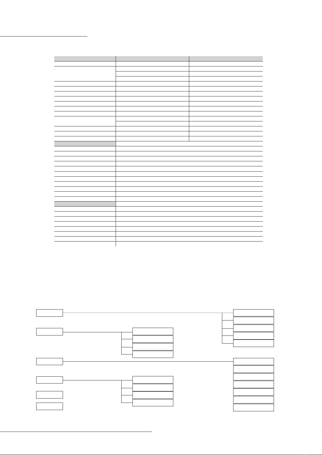
IF you use Peoco-D or Pelco-P protocol in your controller, you can access the main menu
by programming
(saving or calling) preset 95.
STARTING OSD MENU (NENU/PRESET 95)
SYSTEM
DISPLAY
DOME
CAMERA
ALARM
EXIT
OSD SETUP
AREA TITLES
PRIVACY ZONE
IMAGE SETUP
FOCUS/ZOOM
W-BALANCE
EXPOSURE
ADVANCED
INFO
REBOOT
FACTORY
EVENT LOG
PASSWORD
GENERAL
MOTION
HOME
PRESET
TOUR
PATTERN
SCAN
27X / 37X NTSC 27X / 37X PAL
1/4 inch, Interline Transfer CCD
37x Optical, f=3.4 to 129.5mm (F1.6~F3.9)
27x Optical, f=3.5 to 94.4mm (F1.6~F2.8)
16x Digital Zoom
1,500mm
2:1 Interlace
H: 15.734 KHz / V: 59.94 Hz
1020(H) x 508(V)
976(H) x 494(V)
More than 52dB
CVBS : 1.0Vp-p/75Ω
0.2 Lux/F1.6 (Wide,50 IRE) : Color
0.01 Lux/F1.6 (Wide,50 IRE) : B/W
Auto, Color, B/W(ICR), EXT
Auto, ATW, Indoor, Outdoor, Mercury, Manual
CVBS : 1.0Vp-p / 75Ω
1/4 inch, Interline Transfer CCD
37x Optical, f=3.4 to 129.5mm (F1.6~F3.9)
27x Optical, f=3.5 to 94.4mm (F1.6~F2.8)
16x Digital Zoom
1,500mm
2:1 Interlace
H: 15.625 KHz / V: 50.00 Hz
1020(H) x 596(V)
976(H) x 582(V)
More than 52dB
CVBS : 1.0Vp-p/75Ω
0.2 Lux/F1.6 (Wide,50 IRE) : Color
0.01 Lux/F1.6 (Wide,50 IRE) : B/W
Auto, Color, B/W(ICR), EXT
Auto, ATW, Indoor, Outdoor, Mercury, Manual
CVBS : 1.0Vp-p / 75Ω

OPERATION & PROGRAMMING
11
TITLE EDIT
*This title edit menu can be used in OSD Setup/Pattern/Scan/Preset/Area Title commonly.
To edita title:
1.. Use the joystick to position the cursor beside TITLE.
2. Move the joystick right. The following appears on the monitor.
3. Use the joystick right, left, up and/or down to select a character. Press [TELE] button or twist the joystick
clockwise to input a character.
4. Press [WIDE] button or twist the joystick counterclockwise to delete a character.
5. Follow the directions displayed on the monitor.
6. When the label is completed, press [ENT] or [IRIS OPEN] to return to the previous menu.
7. To cancel editing a title, press [CLR] or [IRIS CLOSE] to return to the previous menu.
TITLE:
ABCDEFGHIJKLMNOP
QRSTUVWXYZabcdefg
hijklmnopqrstuvwx
yz0123456789<>/ -:
■Select: <MOVE>
■Save: <ENT> <OPEN>
■Exit: <CLR> <CLOSE>
Check points before operation
Before power is applied, please check the cable carefully.
The camera ID of the controller must be identical to that of the target camera. The camera ID can be checked by reading
Rotary switch of the camera.
If your controller supports multi-protocols, the protocol must be changed to match to that of the camera.
If you change the camera ID by changing Rotary switch, the change will be eective after you reboot the camera.
Since the operation method can be dierent for each controller available, refer to the manual for your controller if camera
can not controlled properly. The operation of this manual is based on the standard pelco controller.
NOTE.
1. Version can be changed by system upgrade.
2. This manual is written by using supplied controller.
3. Temperature can be changed by outside environment.
OSD Display of Main Screen
- Camera ID: If the camera ID was saved by rotary switch as you want, the camera ID will be
displayed on main screen.
- When you move the joystick of controller, the angle of Pan/Tilt will be displayed on main screen.
ID : 001
<180.01,230.00>
Dome ID
The angle of pan/tilt

OPERATION & PROGRAMMING
12
SYSTEM : INFO
The system Information displays Serial Number/model Name
/Running Version/Protocol/
Communication Type/Address switch No.(Camera ID) / Camera internal temperature.
System settings cannot be edited in this menu. This screen is for reference only..
Use the following steps to display the system information screen:
1. Push the MENU key
2. To move the right position by using joystick.
Note.
-Version can be changed by system upgrade.
-Temperature can be changed by outside environment
<< SYSTEM INFORMATION >>
██████████████████████████
S/N:0-00-00-000-00000
MODEL :XXX-XXXX
VERSION :XXX-XXXX
VIDEO :NSTC or PAL
PROTOCOL :STANDARD
COMM. :RS485/02400
ADDRESS :001
TEMP. :044.0C/111.2F
██████████████████████████
■ Exit: <ESC> <CLOSE>
<<<<< Main MENU >>>>>
██████████████████████████
► SYSTEM > INFO
DISPLAY > REBOOT
DOME > FACTORY
CAMERA > EVENT LOG
ALARM > PASWORD
EXIT
<<<<< Main MENU >>>>>
██████████████████████████
► SYSTEM >
DISPLAY >
DOME >
CAMERA >
ALARM >
EXIT
<<<<< Main MENU >>>>>
██████████████████████████
► SYSTEM > INFO
DISPLAY ► REBOOT
DOME > FACTORY
CAMERA > EVENT LOG
ALARM > PASWORD
EXIT
SYSTEM : REBOOT
In case of no control or no operating, we recommend you
should have rebooting.
Use the following steps to display the system information
screen:
1. Press the menu key
2. To move the right position by using Joystick
3. Select reboot
4. To reboot the system, Press [ENT] or [OPEN]
To cancel reboot, Press [ESC] or IRIS [CLOSE] key
■Reboot: <ENT> <OPEN>
■ Exit: <CLR> <CLOSE>
<<<<< Main MENU >>>>>
██████████████████████████
► SYSTEM >
DISPLAY >
DOME >
CAMERA >
ALARM >
EXIT
<<<<< Main MENU >>>>>
██████████████████████████
►SYSTEM >
DISPLAY >
DOME >
CAMERA >
ALARM >
EXIT
<<<<< Main MENU >>>>>
██████████████████████████
►SYSTEM > INFO
DISPLAY > REBOOT
DOME > ►FACTORY
CAMERA > EVENT LOG
ALARM > PASWORD
EXIT
SYSTEM : FACTORY
After saved the parameters for camera , preset, tour, pattern
and scan mode, If user want to
remove the old parameters,
please use “ factory setup “.
Use the following steps to display the System Information
screen:
1. Press the MENU key
2. Select SYSTEM using joystick.
3. Select FACTORY
4. Select items to be reset.
5.
Press [ENT] button or move the cursor to <SAVE and EXIT>
and then move the right position
by using joystick..
ALL : OFF -> All of old parameters is saved.
ALL : ON -> All of old parameters is removed.
Cam , Preset, Tour, Pattern Scan are same as above.
██████████████████████████
██████████████████████████

OPERATION & PROGRAMMING
13
SYSTEM : EVENT LOG
Event Log shows the current dome status and dome event logs.
If the dome have some problems, It displays error message and
save the logs to EEPROM.
Use the following steps to display the EVENT LOG screen:
1. Press the MENU key
2. Select system using joystick.
3. Select EVENT LOG.
4.
Code : <number> means number of
error occurred during camera operation.
When you scroll up and down using joystick,
you can nd what
kinds of error for
during the operation.
5.
Press the [ESC] or [IRIS CLOSE] key to return
the previous
menu.
<<<< EVENT LOG >>>>
██████████████████████████
Code:0000,Cnt:00,Drp:000
None............
-----------------------
►01.00 Empty...........
02.00 Empty...........
03.00 Empty...........
04.00 Empty...........
05.00 Empty...........
██████████████████████████
Exit: <ESC> <CLOSE>
██████████████████████████
██████████████████████████
██████████████████████████
<<<<< Main MENU >>>>>
██████████████████████████
►SYSTEM >
DISPLAY >
DOME >
CAMERA >
ALARM >
EXIT
SYSTEM : PASSWORD
If you have new password, the dome will be protected from
unauthorized user.
An operator cannot access any of the Dome Setting menus.
Controller / keyboard commands cannot override password-
protected settings.
If the keyboard is used to set a preset, pattern, or zone, The Enter Password screen appears on the monitor.
Use the following steps to set up password :
1. Press the MENU key.
2. Select SYSTEM using joystick.
3.
Select PASSWORD in the sub menu of SYSTEM using joystick.
4. Select number using joystick left/right and press the or Twist Joystick to clockwise.
5. To enable password set ENABLE:ENABLED
6. [ENT] or [IRIS OPEN] Key Password save. [ESC] or [IRIS COLSE] Key Return Prievious menu move.
Note.
-The default password is “0000”
-User have to remember it if the password is changed.
<<<<< Main Menu >>>>>
██████████████████████████
►SYSTEM > INFO.
DISPLAY > REBOOT
DOME > FACTORY
CAMERA > EVENT LOG
ALARM ►PASSWORD
EXIT
PASSWORD
██████████████████████████
►CURRENT: x---
NEW : ----
CONFIRM: ----
ENABLE : DISABLED
██████████████████████████
x12456789
<<<<< Main Menu >>>>>
██████████████████████████
►SYSTEM >
DISPLAY >
DOME >
CAMERA >
ALARM
EXIT
DISPLAY : OSD SETUP
OSD setup allows you to program how labels are displayed on the monitor.
The following labels are available :
TITLE Identies area and operation titles.
TIME Identies dwell time.
ZOOM Identies the amount of magnication.
Zoom ratio (Tele and wide) is displayed on the monitor
when you control the Joystick.
You can select “OFF”or “3 Sec ( Default)”
ID Identies camera address.
MODE Identies dome operation mode such as preset, scan...
ANGLE The angle of pan/tilt is displayed on the monitor when you control the Joystick.
You can select “OFF”or 3 Sec (Default)~9Sec.
Labels can be placed anywhere on the monitor. This feature allows
you to customize the
appearance of your monitor screen.
To set a label position :
1. Press the MENU key
2. Select DISPLAY using joystick.
3. move the right position to“OSD SETUP”.
4.
move the Joystick to up/down and left /right, and then,
select
the OSD label for Each functions.
5. Select <Save and Exit> to save settings and exit menu.
6.
Select <Exit without Saving> to exit menu without saving settings.
<< OSD SETUP >>
██████████████████████████
►TITLE : OFF
TIME : OFF
ZOOM : 3 SEC
ID : ON
MODE : ON
ANGLE : 3 SEC
██████████████████████████
<Save and Exit>
<Exit without Saving>
Twist joystick to clockwise
or press [TELE] button
<<<<< Main Menu >>>>>
██████████████████████████
SYSTEM >
►DISPLAY >
DOME >
CAMERA >
ALARM
EXIT
<<<<< Main Menu >>>>>
██████████████████████████
SYSTEM >
►DISPLAY >►OSD SETUP
DOME > AREA TITLES
CAMERA > PROIVACY ZONE
ALARM IMAGE SETUP
EXIT

OPERATION & PROGRAMMING
14
<<<<< Main Menu >>>>>
██████████████████████████
SYSTEM >
►DISPLAY > OSD SETUP
DOME > ►AREA TITLES
CAMERA > PRIVACY ZONE
ALARM IMAGE SETUP
EXIT
DISPLAY : AREA TITLES
If user want to see the name of Area Title on the monitor, user have to save the Area Title from
Starting position to Stop position.
The dome system is capable of 8 area titles, each with a 12 character label.
To program a zone :
1. Press the MENU key
2. Select display -> “AREA TITLLE” using joystick.
3. select zone ID (No.xxx). and then,
Press the [TELE] button or turn the joystick clockwise direction.
4. Move the joystick to position start limit angle and Press [ENT] or [IRIS OPEN]
to save START limit angle.
5. Move the joystick to position start limit angel and Press [ENT] or [IRIS OPEN]
to save STOP limit angle6. Edit a title, See [TITLE EDIT] section for detail.
<< AREA TITLE SETUP >>
██████████████████████████
►NO.001 : █•••••••
TITLE :
-START :
-STOP :
██████████████████████████
<Save and Exit>
<Exit without Saving>
Twist joystick clockwise
or press [+] button
DISPLAY : PRIVACY ZONE
To protect privacy, Max. 24 privacy masks can be created on the arbitrary position to hide
objects such as windows, shops or private house.
With Spherical Coordinates system, powerful privacy zone mask
function is possible.
1. No. xxx : Identies privacy zone ID (1~8ea)
2. Mode : DISABLE – disable privacy zone
BLOCK – Enable privacy zone
3. Privacy Mask : adjust mask size
- PAN/TILT – adjust position
- TELE – enlarge sized mask
- WIDE – small sized mask
To program a privacy zone:
1. Press the MENU key
2. Select DISPLAY -> “PRIVACY ZONE” using joystick.
3. Use the joystick to position the cursor beside NO.xxx. and then, select zone ID.
4.
Press the [TELE] button or twist the joystick to clockwise
direction for setup the zone.
5. Follow the instructions that appear on the screen.
6. Select the zone area by moving joystick. and then press the“ENT”
To disable or clear a Privacy Zone (a zone is enabled automatically when it is Programmed):
1. Use the joystick to position the cursor beside NO.xxx. Move left or right to select zone ID.
2.
Press the [WIDE] button or turn the joystick counterclockwise
to clear.
Twist joystick clockwise or press [TELE] button
<<<<< Main Menu >>>>>
██████████████████████████
SYSTEM >
►DISPLAY > OSD SETUP
DOME > AREA TITLES
CAMERA > ►PRIVACY ZONE
ALARM IMAGE SETUP
EXIT
<< PRIVACY ZONE SETUP >>
██████████████████████████
►NO.001 : █•••
MODE : DISABLE
██████████████████████████
<Save and Exit>
<Exit without Saving>
DISPLAY : IMAGE SETUP
This menu allows operator to change the displayed image
settings.
The following four options are available:
H. Mirror : left-right reverse image
V. Mirror :
Up-down reverse image.
To set up image display
1. Press the MENU key.
2. Select DISPLAY and select IMAGE SETUP using joystick.
3. Select Mirror or Flip mode.
<<<<< Main Menu >>>>>
██████████████████████████
SYSTEM >
►DISPLAY > OSD SETUP
DOME > AREA TITLES
CAMERA > PRIVACY ZONE
ALARM ►IMAGE SETUP
EXIT
<< IMAGE SETUP >>
██████████████████████████
▶H.MIRROR : ON
▶V.MIRROR : ON
██████████████████████████
<Save and Exit>
<Exit without Saving>

OPERATION & PROGRAMMING
15
DOME : GENERAL SETUP
BACK UP TASK
OFF : Even though event( alarm action) is occurred, the preset, tour, pattern and scan is operated
ON (default) : When the event (alarm action ) is occurred,
the camera move to object with detected zone
even though
camera already set preset, tour,
pattern and scan
TURBO SPEED
This setting denes the manual pan and tilt speed.
The following settings are available :
OFF (default) : Max speed is 90 degrees per second.
NO : Max. speed is 180 degrees per second.
Note.
-Turbo speed only applicable to manual operation not for
preset, pattern etc.
PRESET SPEED
You can optimize preset speed with this menu. There are three options : 0~360˚/sec
SELF TEST
This setting denes the diagnostic monitoring activity.
When the dome nds some problems, the error message is
displayed.
For details, see <SYSTEM →EVENT LOG> section in this manual.
The following settings are available: OFF(default) : Disable self test
ON : Enable self test
<<<<< Main Menu >>>>>
██████████████████████████
SYSTEM >
DISPLAY > ►GENERAL
►DOME > MOTION
CAMERA > HOME
ALARM PRESET
EXIT TOUR
PATTERN
SCAN
<< GENERAL SETUP >>
██████████████████████████
VIRTUAL ADDR : 001
►BACKUP TASK : ON
TURBO SPEED : OFF
PRESET SPEED : FAST
SELF TEST : OFF
██████████████████████████
<Save and Exit>
<Exit without Saving>
DOME : MOTION
PROPORTIONAL PAN/TILT
Proportional pan/tilt automatically reduces or increases the pan and tilt speeds according to zoom ratio .
There are two proportional pan/tilt modes:
ON (default) : Enables the proportional pan/tilt mode.
OFF : Disables proportional pan/tilt mode.
AUTO FLIP
In case that tilt angle arrives at the top of tilt orbit (90°),
zoom module camera turns on its axis
by 180° at the top of tilt
orbit and moves to opposite tilt direction (180°) to keep tracing targets.
ON (default) : Auto ip mode is enabled.
OFF : Auto ip mode is disabled.
OVER TILT - To prevent horizontal view due to trim ring or ceiling.
ON : Minimum Tilt Angel is -1.8 degree.
OFF : Minimum Tilt Angle is 4.5 degree.
AZIMUTH ZERO
Azimuth zero is the pan angle from 0° to 359°. Azimuth zero
is the pan Position you specify to
be the 0° point. Azimuth
zero is normally set to Magnetic north. Once set, azimuth is
based
on the set Azimuth zero point.
To set Azimuth zero :
1. Use the joystick to position the cursor beside AZIMUTH ZERO.
2. Press [TELE] or twist the joystick clockwise.
3. Follow the directions displayed on the monitor.
To clear Azimuth zero :
1. Use the joystick to position the cursor beside AZIMUTH ZERO.
2. Press [WIDE] or twist the joystick counterclockwise.
LIMIT STOP- You can make the range of Pan angle as you want.
To set limit stop function :
1. Use the joystick to position the cursor beside Limit stop.
2. Press [TELE] or twist the joystick clockwise.
3. Follow the directions displayed on the monitor.
To clear limit stop function :
1. Use the joystick to position the cursor beside limit stop.
2. Press [WIDE] or twist the joystick counterclockwise.
<< MOTION SETUP >>
██████████████████████████
PROP. PAN/TILT: ON
AUTO FLIP : ON
OVER TILT : ON
AZIMUTH ZERO : OFF
►LIMIT STOP : OFF
-LEFT LIMIT :
-RIGHT LIMIT :
██████████████████████████
<Save and Exit>
<Exit without Saving>
<<<<< Main Menu >>>>>
██████████████████████████
SYSTEM >
DISPLAY > GENERAL
►DOME > ►MOTION
CAMERA > HOME
ALARM PRESET
EXIT TOUR
PATTERN
SCAN
<< MOTION SETUP >>
██████████████████████████
►PROP. PAN/TILT: ON
AUTO FLIP : ON
OVER TILT : ON
AZIMUTH ZERO : OFF
LIMIT STOP : OFF
-LEFT LIMIT :
-RIGHT LIMIT :
██████████████████████████
<Save and Exit>
<Exit without Saving>

OPERATION & PROGRAMMING
16
DOME : HOME
This function enables to locate the camera to specic position
automatically if operator doesn’t operate the controller for a while.
The Home time can be dened as a interval from1 minute to 240 minute.
Note.
-In order to call action preset, tour, pattern or scan, firstly you must
save preset, tour, pattern or scan.
MODE
AUTO (default) : Enable HOME function.
MANUAL : Disables
<<<<< Main Menu >>>>>
██████████████████████████
SYSTEM >
DISPLAY > GENERAL
►DOME > MOTION
CAMERA > ►HOME
ALARM PRESET
EXIT TOUR
PATTERN
SCAN
<< HOME SETUP >>
██████████████████████████
►ACTION : HOME
NUMBER :
TIME : 120 min
MODE : AUTO
██████████████████████████
<Save and Exit>
<Exit without Saving>
DOME : PRESET
Max. 256 Positions can be saved as preset position.
The Preset number can be assigned from 1 to 256.
All characteristics can be set up in OSD menu.
1. Use the joystick to position the cursor beside NO.xxx. Move left or right to select preset ID.
2. Press the [TELE] button or turn the joystick clockwise to Edit a preset position.
3. Follow the directions displayed on the monitor.
4. Edit a title. See [TITLE EDIT] section for details.
* If the title is displayed on the monitor, you have to set rst as follow;
Menu-> Display-> OSD Setup-> Title ON
5. Edit a dwell time - You can select the time from 1~240 sec.
To clear a PRESET :
1. Use the joystick to position the cursor beside NO.xxx. Move the joystick left or right to
select preset ID.
2.
Press the [WIDE] button or turn the joystick “counterclockwise”
to Clear a preset.
Note.
- Press [ENT] or [IRIS OPEN] key to save settings and exit to
previous menu.
-
Press [Esc] or [IRIS CLOSE] key to go to previous menu
without saving any
settings at any time.
<<<<< Main Menu >>>>>
██████████████████████████
SYSTEM >
DISPLAY > GENERAL
►DOME > MOTION
CAMERA > HOME
ALARM ►PRESET
EXIT TOUR
PATTERN
SCAN
<< PRESET SETUP >>
██████████████████████████
►NO.001 : Empty
TITLE :
DWELL :
-PTZ :
██████████████████████████
<Save and Exit>
<Exit without Saving>
DOME : TOUR
The Tour function allows running sequence of presets, pattern
nd /or Tour. Max 8 tour can
be saved. Each group can have
Max 30 action entitles which can be preset, pattern or scan.
Preset Speed can be set up and the repeat number of pattern & scan can be set up in tour.
Dwell time between actions can be set up also.
To program a tour.
1. Press the MENU key .
2. Select DOME and select Tour by using joystick.
3.
Use the joystick to position the cursor beside NO.xxx. Move
left or right to select tour ID.
and then, Press the [TELE]button
or twist the joystick clockwise to setup.
4. To insert items. Use following steps :
- To save the preset.
- Move the joystick to position the cursor beside XXX.
-
Press the [TELE] button or twist the joystick clockwise to select
the preset number.
- To save the Scan or Pattern,
1) Move the joystick to position the cursor beside XXX.
2) Please push the [NEAR] or [FAR button] on the keyboard. You can select Scan or Pattern.
5. Follow the directions displayed on the monitor.
Before select a specic item, the Preset, Tour, pattern and
scan is already saved.
To disable or clear a tour.
1.
Use the joystick to position the cursor beside NO.xxx. Move
left or Right to select tour ID.
2.
Press the [WIDE] button or turn the joystick “counterclockwise”
to clear.
<<<<< Main Menu >>>>>
██████████████████████████
SYSTEM >
DISPLAY > GENERAL
►DOME > MOTION
CAMERA > HOME
ALARM PRESET
EXIT ►TOUR
PATTERN
SCAN
<< TOUR SETUP >>
██████████████████████████
►NO.001 : Empty
=== === === === === ===
=== === === === === ===
=== === === === === ===
=== === === === === ===
=== === === === === ===
██████████████████████████
<Save and Exit>
<Exit without Saving>

OPERATION & PROGRAMMING
17
DOME : PATTERN
Pattern function is that a camera memorizes the path by joystick of controller for assigned time
and revives the path exactly as it memorized. 8patterns are available.
To program a pattern :
1. Press the MENU key
2. Select DOME and select PATTERN using joystick.
3.
Use the joystick to position the cursor NO.xxx. Move left or right
to select pattern ID.
4.
Press the [TELE] button or twist the joystick clockwise to start
to learn.
5. Follow the directions displayed on the monitor.
6. To save, press [ENT] or [IRIS OPEN] key. To cancel press [CLR] or [IRIS CLOSE] key.
7. Edit title. Refer to [TITLE DEIT] section in this manual.
To clear a pattern :
1.
Use the joystick to position the cursor beside NO.xxx. Move the
Joystick left or right to
select a pattern ID.
2. Press the [WIDE] key or turn the joystick counterclockwise.
*
You can access this pattern setting menu with [PRTN] key in
supplied controller.
<<<<< Main Menu >>>>>
██████████████████████████
SYSTEM >
DISPLAY > GENERAL
►DOME > MOTION
CAMERA > HOME
ALARM PRESET
EXIT TOUR
►PATTERN
SCAN
<< PATTERN SETUP >>
██████████████████████████
►NO.001 : █•••••••
TITLE :
-TIME :
██████████████████████████
<Save and Exit>
<Exit without Saving>
DOME : SCAN
You can make camera to move between 2 preset positions repeatedly.
When Scan function runs, camera moves from the preset assigned
as the 1st Point to the preset
assigned as the 2nd point in the direction of the path chosen by the user.
Then camera moves from the preset assigned as the 2nd point to
the preset assigned as the 1st
point in the reverse direction.
To program a scan :
1. Press the MENU key .
2. Select DOME and select Scan using joystick.
3.
Use the joystick to position the cursor beside NO.xxx. Move
left or right to select a
scan number.
4. Press the [TELE] key or turn the joystick clockwise to start to setup start and stop position.
5. Edit a title. Refer to [TITLE EDIT] section in this manual.
6. Select scan speed. Scan speed is from 1step~9step. (default: 5 step)
7. Edit a dwell time - You can select the time from 1~240 sec.
To clear a scan :
1.
Use the joystick to position the cursor beside NO.xxx. Move the
joystick left or right to
select a scan number.
2. Press the [WIDE] key or turn the joystick “counterclockwise”. How to activate a scan
Press the specic number key and then press [SCAN].
Ex) [1]+[SCAN]
You can also access this menu with [SCAN] key.
Note.
-
Press [ENT] OR [IRIS OPEN] key to save settings and exit to
previous menu or Press [Esc] or [IRIS CLOSE]
key to go to
pervious menu without saving any settings at any time.
<<<<< Main Menu >>>>>
██████████████████████████
SYSTEM >
DISPLAY > GENERAL
►DOME > MOTION
CAMERA > HOME
ALARM PRESET
EXIT TOUR
PATTERN
►SCAN
<< SCAN SETUP >>
██████████████████████████
►NO.001 : █•••••••
TITLE :
SPEED : 5
DWELL : 005 sec.
-MODE :
-START :
-STOP :
██████████████████████████
<Save and Exit>
<Exit without Saving>

OPERATION & PROGRAMMING
18
CAMERA : FOCUS/ZOOM
FOCUS
There are three auto focus settings :
AUTO:
If auto focus mode is set to auto. The camera will focus
automatically.
MANUAL:
Focus is operated manually. To focus, press [NEAR] or
[FAR] key on the controller.
TRIGGER
(default) : If auto focus mode is set to TRIGGER, the
camera will focus when zoom
functions.
Note.
- Auto focus will malfunction at below condition.
: very dark or shiny area when slow shutter is activated area which doesn’t have contrast
difference
Z.SPEED
There are three zoom speed setting
- FAST / NORMAL / LOW
D.ZOOM(Digital Zoom) : To enable digital zoom, set. D.ZOOM to ON. The default value is ON.
Note.
-
Press [ENT] or [IRIS OPEN] key to save settings and exit to
previous menu.
-
Press [Esc] or [IRIS CLOSE] key to go to previous menu without
saving any settings at any time
<<<<< Main Menu >>>>>
██████████████████████████
SYSTEM >
DISPLAY >
DOME > ►FOCUS/ZOOM
►CAMERA > W-BALANCE
ALARM EXPOSURE
EXIT ADVANCED
RESET
<< FOCUS/ZOOM SETUP >>
██████████████████████████
►FOCUS : TRIGGER
Z.SPEED : LOW
D.ZOOM : ON
██████████████████████████
<Save and Exit>
<Exit without Saving>
CAMERA : W – BALANCE
This feature automatically processes the viewed image to retain color balance over temperature range.
The default setting for white balance is auto.
White Balance has following four modes.
ATW
This mode automatically adjusts color temperature range from 1800K to 10500K. It can
select INDOOR, OUTDOOR and MERCURY mode.
INDOOR
Automatic White Balance for in door. 3200K base mode.
OUTDOOR
Automatic White Balance for outdoor. 5800K base mode.
MANUAL
R/B gain can be adjusted by manual.
AWC
Whenever this mode is sent, camera becomes ATW mode to adjust color temperature.
After it nished, color temperature is xed.
*Note
- Auto white balance will malfunction at below condition.Very dark or shiny area (clear sky, sunset)
Direct shot of uorescent
lamp or much dierence brightness
area.
- Press [ENT] or [IRIS OPEN] key to save settings and exit to
previous menu or Press [Esc] or [IRIS CLOSE] key to exit to
previous menu without saving any settings at any time.
<<<<< Main Menu >>>>>
██████████████████████████
SYSTEM >
DISPLAY >
DOME > FOCUS/ZOOM
►CAMERA > ►W-BALANCE
ALARM EXPOSURE
EXIT ADVANCED
RESET
<< WB SETUP >>
██████████████████████████
►MODE : AUTO
R GAIN :
B GAIN :
██████████████████████████
<Save and Exit>
<Exit without Saving>

OPERATION & PROGRAMMING
19
CAMERA : EXPOSURE
The variety of Auto Exposure functions, which allow video signal
to output the optimum image for
subjects from low light condition
to high light conditions, is available.
FULL AUTO
Auto Iris and Gain, Fixed shutter speed (NTSC:1/60, PAL:1/50)
Manual
Variable Shutter, Iris, Gain and DSS ON/OFF
Shutter Fix / Iris Fix / AGC Fix
Fixed, and gives the exposure control priority to other resources.
Note.
If auto iris is in the auto mode, it will remain that way until the
lris is manually opened or closed.
The dome will return to auto
mode when it is panned or tilted.
<<<<< Main Menu >>>>>
██████████████████████████
SYSTEM >
DISPLAY >
DOME > FOCUS/ZOOM
►CAMERA > W-BALANCE
ALARM ►EXPOSURE
EXIT ADVANCED
RESET
<< AE SETUP >>
██████████████████████████
►MODE : FULL AUTO
IRIS :
SHUT :
GAIN :
SSNR :
DSS :
██████████████████████████
<Save and Exit>
<Exit without Saving>
CAMERA : ADVANCED SETUP
SHARPNESS
Settings ranges from 0 to 15. Enhances picture detail by
increasing the aperture gain of the
camera and sharpening
the edges in the picture.
BACK LIGHT(BLC)
Back light compensation enhances objects in the center of
the picture.
The dome uses the center of the picture to adjust the iris.
If there is a bright light source outside of this area, it will
wash out to white. The camera will
adjust the iris so that the object in the sensitive area is property exposed.
LOW / MIDDLE / HIGH
DAY & NIGHT
Auto ICR Mode automatically switches the settings needed for attaching or removing IR Cut lter.
AUTO / ON / OFF
BRIGHTNESS
Settings ranges from 0 to 100. Increases as the number gets higher.
<<<<< Main Menu >>>>>
██████████████████████████
SYSTEM >
DISPLAY >
DOME > FOCUS/ZOOM
►CAMERA > W-BALANCE
ALARM EXPOSURE
EXIT ►ADVANCED
RESET
<< ADVANCED SETUP >>
██████████████████████████
►SHARPNESS : 04
BACKLIGHT : LOW
DAY&NIGHT : AUTO
BRIGHTNESS : 050
██████████████████████████
<Save and Exit>
<Exit without Saving>
CAMERA : RESET
In case of deleting all setting as default, this function is used.
■Reboot: <ENT> <OPEN>
■ Exit: <CLR> <CLOSE>

OPERATION & PROGRAMMING
20
ALARM
IN (4ea of ALARM INPUT)
NO Normal Open.
NC Normal Close.
OUT (1ea of ALARM OUTPUT)
1. Go to “No.001”- > turn the joystick with clockwise.
If you cancel, please turn the joystick with counter-clockwise.
2. Go to “In”- > please set the NO or NC.
3. Go to “Out” - > please set the “001” or o.
- “001” means input “ON”
- OFF(default) : No action.
4. PRIORITY : You can set the priority order for Alarm 1.2.3.4
5. ACTION : In case of alarm event, go to the preset or pattern or scan, tour.
6. Number : That means the number of preset or pattern or scan, tour which is already set the
each menu.
7. Dwell : That means how long is ring the sound, also how long take a action event.
8. To save
9. To disable an alarm : If you want cancel the alarm event, please move to joystick and then go to the“No.xxx”(alarm number).
Press the <WIDE> button or turn the joystick counterclockwise.
If the joystick is moved, the alarm setting will be stopped for 10 sec.
High Speed Dome Alarm Cable
<< ALARM SETUP >>
██████████████████████████
►NO.001 : █•••
IN :
OUT :
PRIORITY:
ACTION :
NUMBER :
DWELL :
██████████████████████████
<Save and Exit>
<Exit without Saving>
<<<<< Main Menu >>>>>
██████████████████████████
SYSTEM >
DISPLAY >
DOME >
CAMERA >
►ALARM
EXIT
1
2
3
4
Brown / White
Red / White
Orange / Black
Brown
Alarm 0
Alarm 1
Alarm 2
Alarm 3
5
6
7
8
Black / White
Yellow / Black
Green / White
Blue / White
GND
NO
COM
NC
Alarm input schematic method (ex. alarm 0)
EX) NO or NC Type magnetic Sensor Schematic
OSD Alarm In
Alarm input NC setting
Alarm input NO setting
Alarm input NC setting
Alarm input NO setting
Magnetic
Sensor Type
NO type
NC type
Open (alarm operating)
Open (alarm disable)
Usually 0.01Ω(alarm disable)
Usually 0.01Ω(alarm operating)
Usually 0.01Ω(alarm disable)
Usually 0.01Ω(alarm operating)
Open(alarm operating)
Open(alarm disable)
This manual suits for next models
1
Table of contents
Other Twilight Security Camera manuals