408-8473
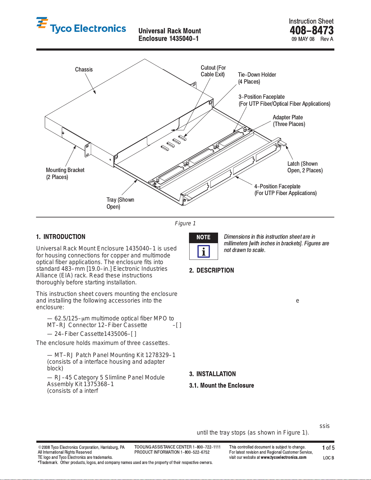
Un versal Rack Mount Enclosure 1435040-1
Rev
A2
of 5 Tyco E ectronics Corporation
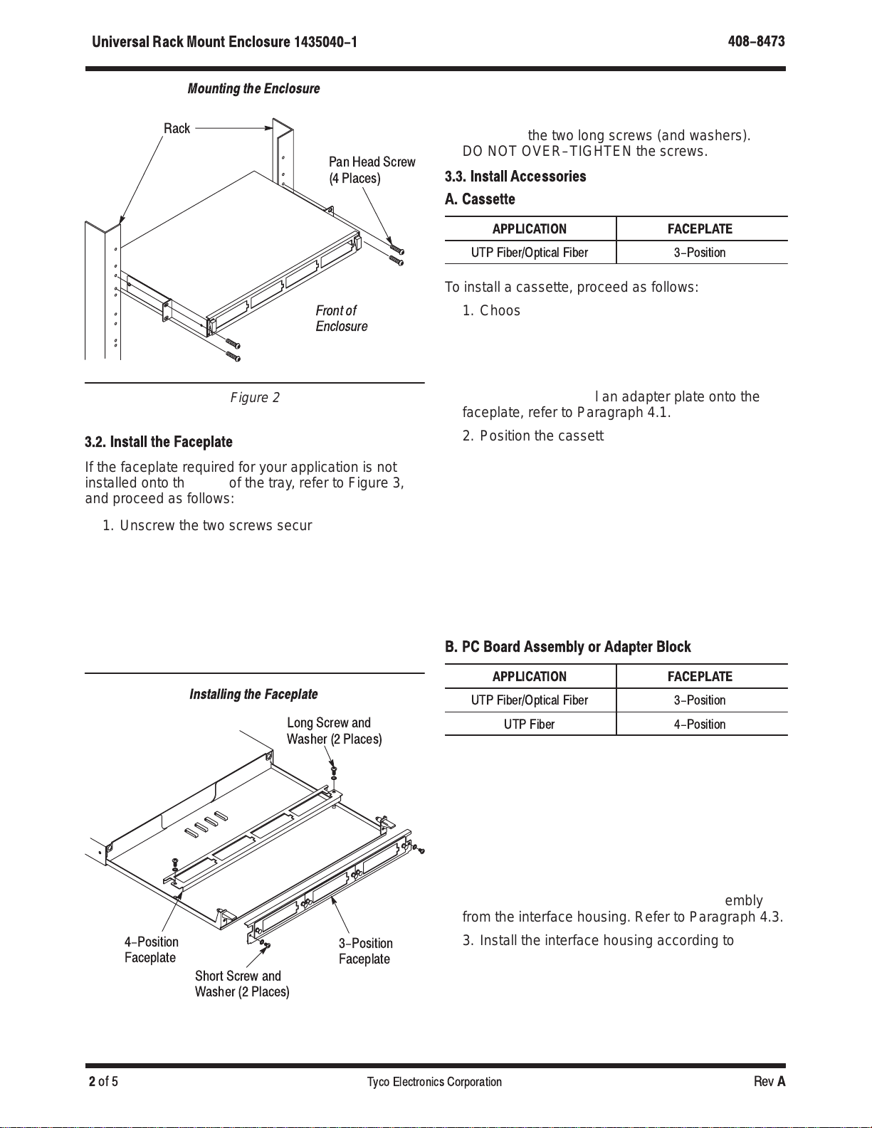
Figure 2
Mounting the Enclosure
Rack
Front of
Enclosure
Pan Head Screw
(4 P aces)
3.2. Install the Faceplate
If the faceplate required for your application is not
installed onto the front of the tray, refer to Figure 3,
and proceed as follows:
1. Unscrew the two screws securing the faceplate
onto the base of the tray. Lift the faceplate away
from the tray. Retain these long screws and the
washers.
2. Unscrew the two screws securing the faceplate
onto the front of the tray. Pull the faceplate away
from the tray. Retain these short screws and the
washers.
Figure 3
Installing the Faceplate
Long Screw and
Washer (2 P aces)
Short Screw and
Washer (2 P aces)
4-Position
Facep ate 3-Position
Facep ate
3. Secure the faceplate to be used onto the front of
the tray using the two short screws (and washers),
and secure the other faceplate onto the base of the
tray using the two long screws (and washers).
DO NOT OVER–TIGHTEN the screws.
3.3. Install Accessor es
A. Cassette
APPLICATION FACEPLATE
UTP Fiber/Optica Fiber 3-Position
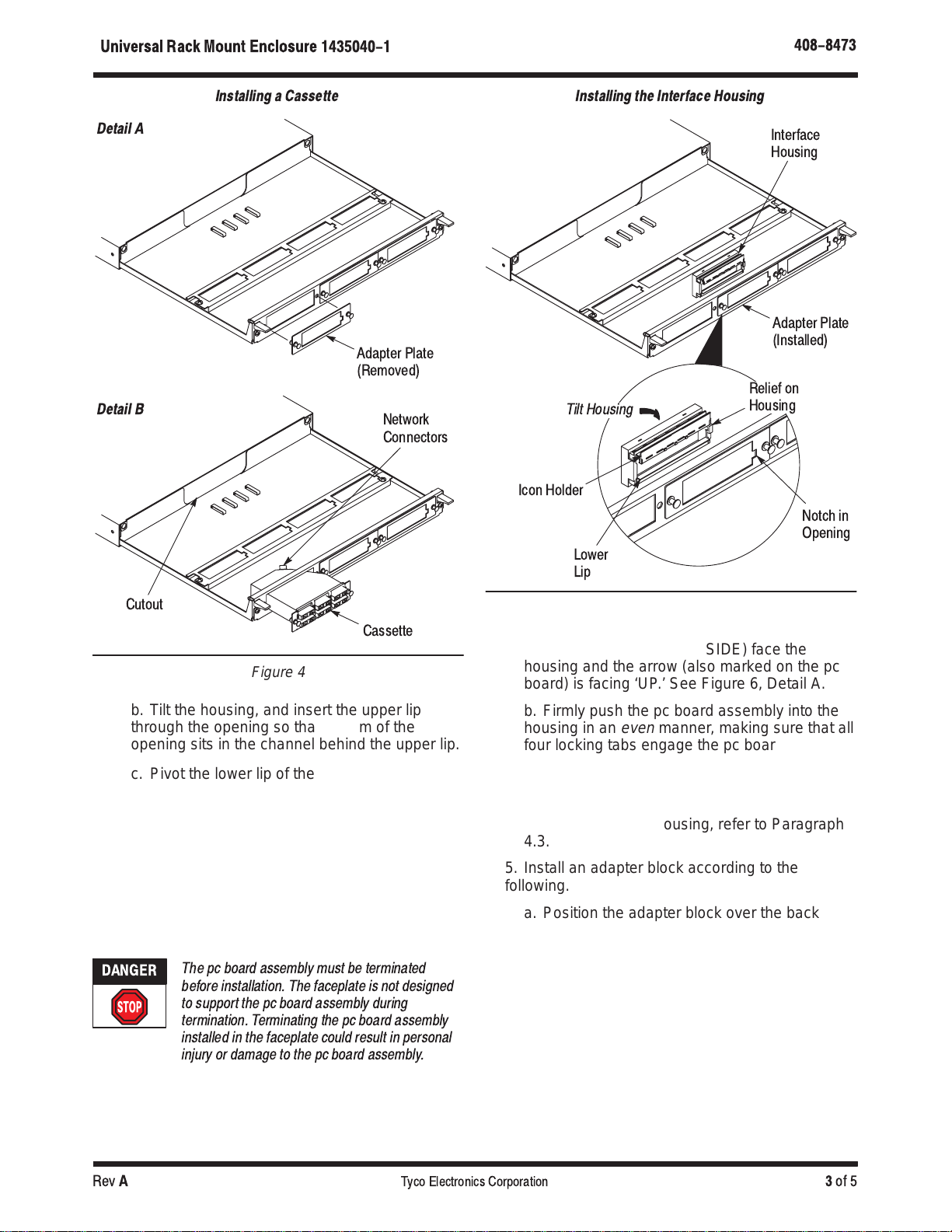
To install a cassette, proceed as follows:
1. Choose the opening (position) in the faceplate to
install the cassette. Pull the lock pins of the
adapter plate until the adapter plate releases from
the faceplate. See Figure 4, Detail A. Retain the
adapter plate.
If necessary, to install an adapter plate onto the
faceplate, refer to Paragraph 4.1.
2. Position the cassette over the front of the
opening in the faceplate. Orient the cassette so
that the split end of the lock pins align with the
holes in the faceplate and the network connectors
(connectors at the back of the cassette) face the
cutout in the tray. Feed the cassette through the
opening, and push the lock pins into the holes until
the cassette is flat against the faceplate and
secure (there will be an audible “click”). See Figure
4, Detail B.
If necessary, to remove a cassette from the
faceplate, refer to Paragraph 4.2.
B. PC Board Assembly or Adapter Block
APPLICATION FACEPLATE
UTP Fiber/Optica Fiber 3-Position
UTP Fiber 4-Position
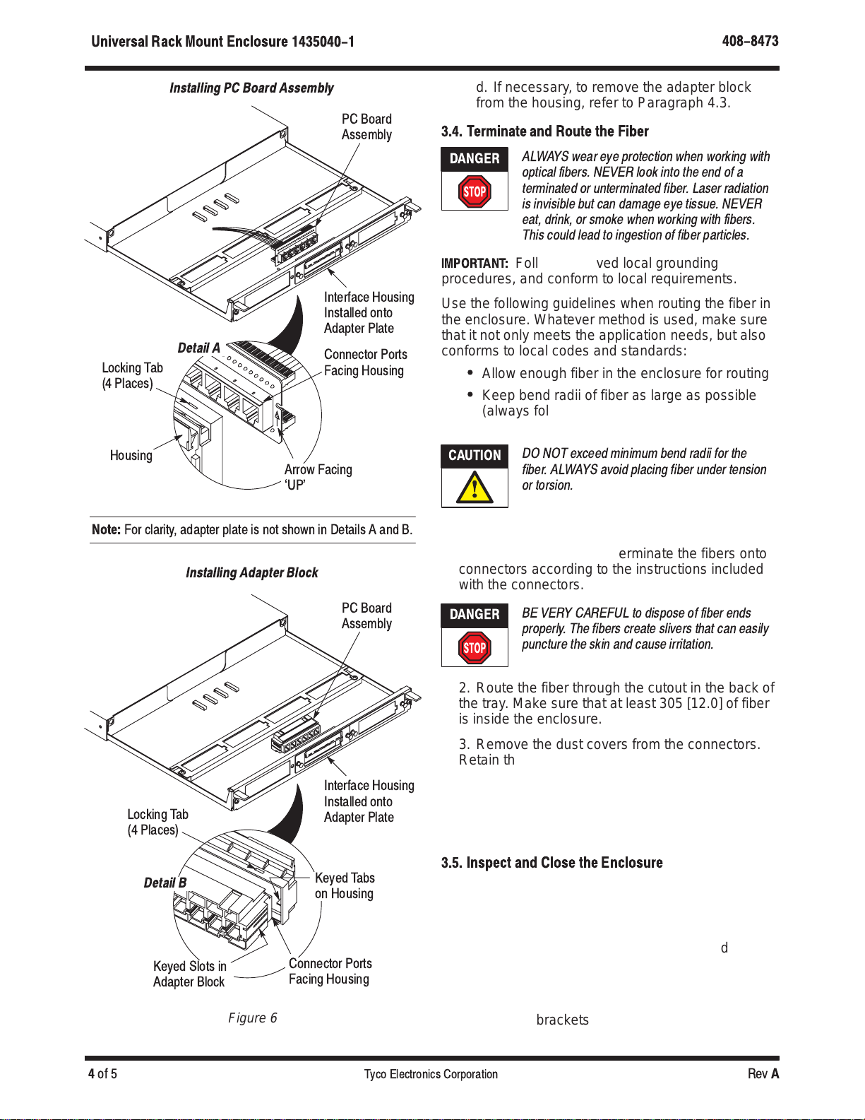
To install a pc board assembly or adapter block,
proceed as follows:
1. Choose the opening (position) in the faceplate to
install the patch panel or module. For the
3–position faceplate, the adapter plate must be
installed onto the faceplate. If necessary, to install
the adapter plate onto the faceplate, refer to
Paragraph 4.1.
2. If assembled, remove the pc board assembly
from the interface housing. Refer to Paragraph 4.3.
3. Install the interface housing according to the
following. Refer to Figure 5.
a. Position the interface housing over the back
of the opening in the faceplate. Orient the
housing so that the relief aligns with the notch in
the opening.


 user manual")


