Tyler Middle Mount II User guide

Tyler Camera Systems 14218 Aetna Street Van Nuys, CA 91401 • 800.390.6070 • www.tylermount.com
Stratton Camera Inc. 23560 Haggerty Rd Farmington Hills, MI 48335 • 248.427.6400
GYRO-ASSIST
SETUP MANUAL
Tyler Middle Mount II Gyro-Assist for Film or Video cameras.
PLEASE RETURN THIS MANUAL WITH EQUIPMENT
$50.00 CHARGE FOR MANUAL IF NOT RETURNED. CAN BE DOWNLOADED FROM www.strattoncamera.com

Refer to the following Installation Manuals
for instructions on installing Tyler Middle Mount II on helicopter:
(Available for download from our web site)
Tyler - Middle Mount
For Bell Jet Ranger / Long Ranger
206 & 206L Series Helicotpers
Tyler - Middle Mount
For Eurocopter Astar / Twinstar
AS-350 & AS-355 Series Helicotpers

FILM CAMERA REQUIREMENTS
• Compatible cameras: Arriflex 35-3 435, 16/SR-2 & 3 and 16/SR-2 & 3 Hi-Speed.
• 400’ magazine.
• Round filter and shade system - Suggested filter size: 138mm round.
BROADCAST VIDEO CAMERA NOTES
• To ensure there is no noise being picked up from the gyros, make a test recording (with gyros on)
and play back. Also, have pilot “key” the helicopter radio to make sure it is not causing any interfer-
ance with the recording.
POWER (F/V)
•When utilizing the helicopter to power the Gyro Assist (instead of a battery pack), the maxi-
mum current draw is not to excede 28 volts / 400 watts (@ 15 amps).
• The average current draw is approximately 3 amps.
• Suggested power input range: 24 to 28 VDC
Page 1 of 6
NOTES

GYRO-ASSIST PARTS
A INVERTER POWER CABLE
B INVERTER INTERFACE CABLE
- NOT USED WITH NEW STYLE INVERTER
CINVERTER
- NEW STYLE LOOKS SLIGHTLY DIFFERENT
D JUNCTION BOX CABLE
E JUNCTION BOX
F GYRO EXTENSION CABLE
- NOT INCLUDED IF REAR GYRO HAS LONG CABLE
GREAR GYRO & COUNTERWEIGHT ADAPTER BRACKET with T-PI-PIN
H CAMERA GYRO ADAPTER PLATE (WITH GYROS)
I 3/8-16 FLAT HEAD BOLTS (TYPICALLY 1-1/4” LONG)
- OTHER LENGTHS INCLUDED
JLEAD BLOCK
- ADDITIONAL BALAST FOR ARM, TYPICALLY PRE-INSTALLED
AE
H
J
G
F
C
D
B
I
Page 2 of 6


1. Find the fore to aft center of gravity of the camera package.
• Film camera: Assemble the camera and lens using the Tyler lens drive system or other equivalent
bracket, and attach a 400’ magazine.
• Video camera: Attach the Tripod Adapter Plate.
To determine the balance point, place the camera package on top of a rod perpendicular to the cam-
era point-of-view. Place the camera package on its side.
Photo A/B
2. Roughly center the GYRO ADAPTER PLATE on the camera package.
Photo A/B
3. Position the Middle Mount - Quick Release Plate near the center.
Photo A/B
Note: Fasten with two (2) 3/8-16 x 1-1/4 82° FLAT HEAD BOLTS.
4. Remove the Arm Balance Weight from the rear compartment.
Photo C
Note: If there is one lead block attached, proceed to step 5. If there are two lead blocks, re-install
and proceed to step 6.
5. Assemble the Arm Balance Weight with the addition lead block, supplied, then reinstall.
Photo D
6. Use the 1" x 3" POSITIVE LOCK VELCRO to attach the JUNCTION BOX to the Middle Mount
main arm assembly, underneath and forward of the mount power IN connectors. If step 6 has
already been done, proceed to step 7.
Photo E
Note: Clean the surface of the Middle Mount main arm assembly before applying the VELCRO.
8. Attach the rear GYRO ADAPTER BRACKET to the Counterweight. Position the rear socket of
the Turnbuckle assembly on top of the connecting plate on the GYRO ADAPTER PLATE. Insert the
T-Pi-Pin through the turnbuckle assembly and the connecting plate. Secure the GYRO ADAPTER
PLATE by tightening down the large black, plastic knob.
Photo F
Note: If necessary, for additional balance adjustment, loosen the four screws on the connecting
plate to position the GYRO ADAPTER PLATE side to side. Generally it should be closest to the
rotating side of the Counterbalance. For storage, place the original Pi-Pin into the center hole of the
connecting plate.
INSTRUCTIONS
Page 3 of 6
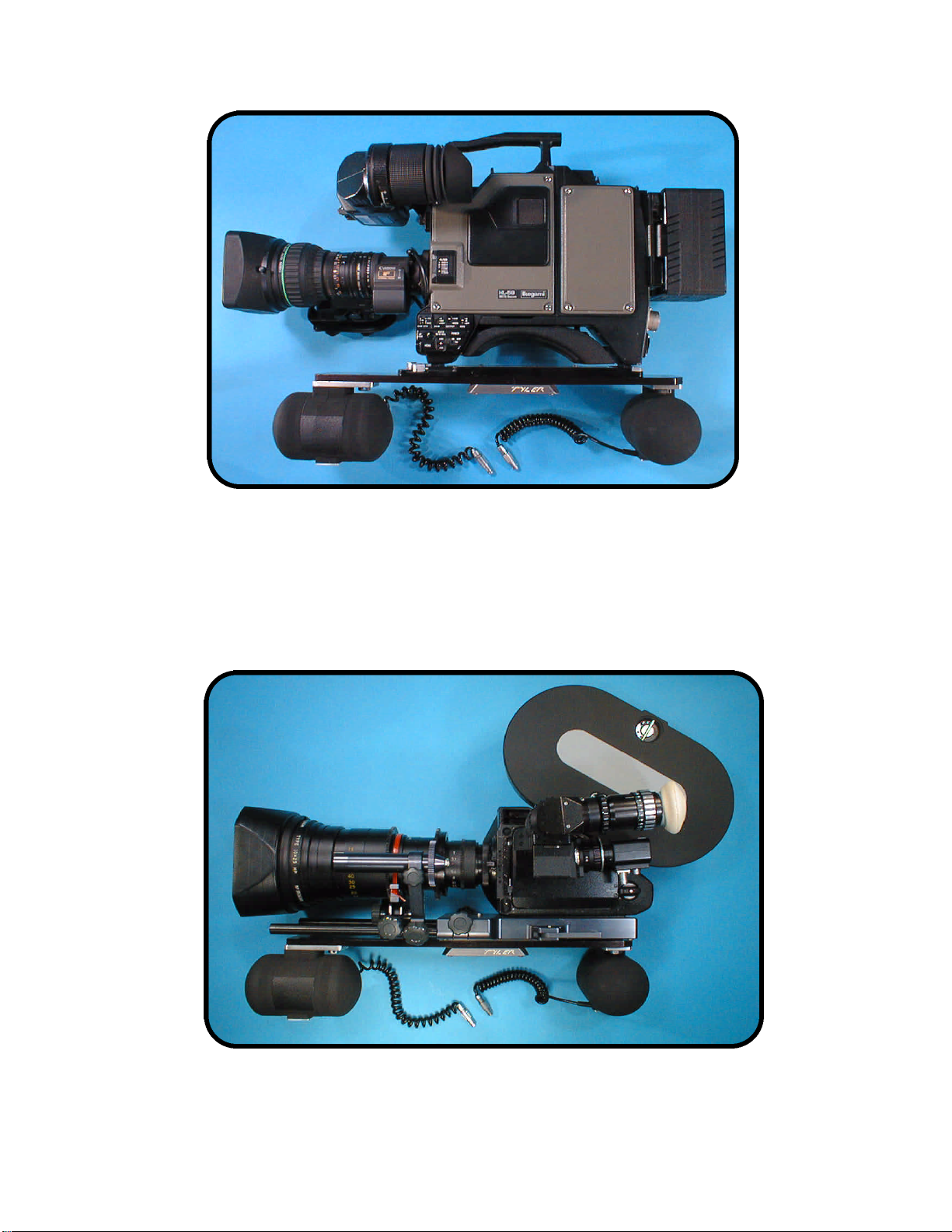
VIDEO CAMERA W/ GYROS
FILM CAMERA W/ GYROS
Page 4 of 6
Photo A
Photo B

ARM BALAST - LEAD WEIGHT
JUNCTION BOX REAR GYRO
Photo C Photo D
Photo E
Note: An optional position to mount the
Junction Box is, on the tilt arm near camera.
Photo F
Page 5 of 6

9. Attach the camera package with gyros onto the Middle Mount.
10. Connect all three GYRO STABILIZERS to the JUNCTION BOX (any order/position).
Photo E
11. Connect the inverter to the JUNCTION BOX using the: 8 ft., 2 pin/male LEMO to: 2 pin/male
LEMO cable.
12. Connect the inverter to a 24 to 28 V camera battery (or other 24 to 28 VDC power supply) using
the: 6 ft., 3 pin/female XLR to: 3 pin/male XLR cable.
Note: pin 1: +V pin 2: GND
AMPHENOL cable
After balancing the Middle Mount the GYRO ASSIST may be turned on. The power On/Off
switch is located on the inverter. The power indicator lamp illuminates when power is switched On.
For optimum performance...
• Balance the Middle Mount with the GYRO ASSIST inactive. Proper balance can only be achieved
when the gyros are NOT spinning.
•Allow the GYRO STABILIZERS to achieve full speed before any attempt is made to move them.
When they are switched On, they slowly gain speed. The spin up period is ten (10) minutes, at
which time the gyros are ready for use.
•Although one 24 to 28 VDC double-block battery can run the GYRO ASSIST three hours, drawing
approximately three amps continuously, it is always a good idea to supply an additional (spare)
battery.
•The gyros must be completely rigid with the Middle Mount, otherwise the operating performance
will be severely diminished. Before each job make sure each gyro unit feels securely fastened.
INSTRUCTIONS (CONTINUED)
Page 6 of 6
Popular Camera Accessories manuals by other brands

Viltrox
Viltrox EF-NEX Mount instructions

Calumet
Calumet 7100 Series CK7114 operating instructions

Ropox
Ropox 4Single Series User manual and installation instructions

Cambo
Cambo Wide DS Digital Series Main operating instructions

Samsung
Samsung SHG-120 Specification sheet

Ryobi
Ryobi BPL-1820 Owner's operating manual


