Tynetec Advent XT2 User manual

DocNo.FM0814issue2
AdventXT2
AssistedLivingCallManagementSystem
_________________________________________________________________________________________________
IP‐DECT
InstallationManual
Tynetecoperatesapolicyofcontinualproductimprovementand
reservestherighttomodifythespecificationofitsproducts.
Ifanyvariationtothedetailsinthisdocumentaresuspectedplease
contactTynetec’sTechnicalSupport.
Tynetec,abusinessunitofLegrandElectricLtd
CowleyRoad,BlythRiversideBusinessPark,Blyth,Northumberland,NE245TF.
T:+44(0)1670352371www.tynetec.co.uk
_______________________________________________________________________________________________________________________
TrustedTechnology
CaringforPeople

DocNo.FM0814issue2Page2
CONTENTS
SectionTopicPage
1ProductOverview 3
2ImportantSafetyInstructions4
3RegulatoryInformation5
4Maintenance&Care 5
5DECTOverview6
6RelatedDocumentation7
7SiteWiringRequirements8
87202/7212DECTHandsets10
9MultiCharger&PSU11
10IP‐DECTServer400&IP‐DECTBaseStation12
11IP‐DECTServer650014
12DECTRepeater15
13DECTRepeaterPSU 16
14MatrixIP‐PBX18
15IP‐DECT400Single‐CellSystemInstallation21
16IP‐DECT400Multi‐CellSystemInstallation28
17IP‐DECT6500SystemInstallation32
18Specification:7202DECTHandset33
19Specification:7212DECTHandset34
20Specification:DesktopCharger&PSU35
21Specification:MultiCharger&PSU36
22Specification:IP‐DECTServer40037
23Specification:IP‐DECTServer650038
24Specification:IP‐DECTBaseStation39
25Specification:Multi‐CellRepeaters40
26Specification:PoEInjector 41
27Specification:16&24PortEthernetSwitches42
28Specification:RepeaterPSU43
29Specification:UninterruptiblePowerSupply44
30Specification:MatrixIP‐PBX45
31AmendmentsRecord46

DocNo.FM0814issue2Page3
1. PRODUCTOVERVIEW
TheDigitallyEnhancedCordlessTelephone(DECT)systemallows2‐wayvoicecommunicationswith
residentsviaAdventXT2wardencallsystemandbetweenstaff,bothinternallyandexternallyifrequired.
WhentheAdventXT2isoperatinginOnsiteModeallalarmcallsarereportedviaDECTsystem.Whenthe
phoneringsthecallerwillbeidentifiedonthedisplay(providedthephonebookmemoryisprogrammed),
whenansweredavoicemessagewillannouncethecalltypeandchannelIDbeforeaspeechlinkisopened.
Thesize/complexityofthebuildingand/orthenumberofDECThandsetsrequiredwilldeterminewhich
oneof3possibleDECTsystemsisinstalled;
1. IP‐DECT400Single‐Cellsystemforsmallinstallations
2. IP‐DECT400Multi‐Cellsystemformostaverage‐sizedinstallations
3. IP‐DECT6500systemforlargeorcomplexinstallations
AllDECTsystemsusethesamehandsets,it’stheServertypeandnumberofBaseStations/Repeatersthat
areneededtoachievesitecoverageandhowtheyareconfiguredwhichdiffers.ThetypeofDECTsystem
andpositioningofBaseStations/Repeaterswillbedeterminedbyasitesurveypriortocommencingthe
installation.
AllBaseStationsarestar‐wiredfromacentralPoEDataSwitchonCat5ecable(maxlength100metres).
Repeatersoperatewirelesslybutrequireconnectiontoabatterybacked12VDCpowersupply.Intheevent
ofamainspowerfailureaUPS(UninterruptablePowerSupply)willmaintainoperationoftheDECTsystem.
TheIP‐PBXallowstheDECThandsetstoaccessanoutsidelinetomake/receivetelephonecallsand
integratewiththeAdventXT2wardencallsystem.TheDECTsystemcanbesetupsoallthewardencall
systemeventsarealwaysalertedtoallhandsets,orday/nightgroupscanbesetsodifferenthandsetscan
bealerteddependingonthetimeofday.Thehandsetscanbeconfiguredintozonessoalertsareonly
notifiedtothestaffresponsibleforspecificareas.

DocNo.FM0814issue2Page4
2. SAFETYINSTRUCTIONS
Readandunderstandtheseinstructionsbeforeuse.RefertotheManufacturersinstallationanduser
guidesformoreinformation(seesection6ofthismanual).Keepallinstructionsforfuturereference.
Takecarewhenworkingonstepladdersduringinstallationorservice.
Isolatethemainssupplybeforeremovingcovers.
Donotdisassembleanypartofthesystemorattempttorepairityourself.
Nouserserviceablepartsinside.Referallservicingtoqualifiedservicepersonnel.
PSU’sshouldonlybeconnectedtoa220‐240VAC50/60Hzmainssupply.Ifyouareunsureofthetype
ofpowersupplyconsultyourlocalpowercompany.
Dangerofexplosionifrechargeablebatteriesareincorrectlyreplaced.UseonlyManufacturer
approvedbatteriesasspecifiedinthismanual.
OnlyuseManufacturerapprovedcableduringinstallation.Seesection7ofthismanualfordetailsof
cabletype,recommendedcolourcodeandcablelengthrestrictions.
DECTproductsshouldbelocatedatleast5metresawayfromanyotherelectronicequipment.
Failuretoprovidethisseparationmayresultinreducedradiorange.
DonotlocateDECTproductsabovearadiatororotherheatsource.
DonotexposeDECTproductstodirectsunlight.
DonotsubmergeDECTproductsinwateranddonotuseindamporhumidconditions.
DonotdroporexposeDECTproductstohighvibrationorshock.
DonotexposeDECTproductstodrippingorsplashingwater.
Liquidscancauseafailureand/orafirehazard.
CleanDECTproductswithadampclothandanon‐abrasivecleaningproduct.Polishwithadryduster.
DONOTuseawetcloth.
Avoidusingharsh,abrasiveorcorrosivecleaningagentsordetergents(e.g.scouringpowders,
bleaches,polishes,etc.)whencleaningDECTproducts.
AttheirendoflifeDECTproductsshouldbedisposedofandrecycledinaccordancewiththe
environmentalregulations.SeetheRegulatoryInformationinsection3ofthismanual.

DocNo.FM0814issue2Page5
3. REGULATORYINFORMATION
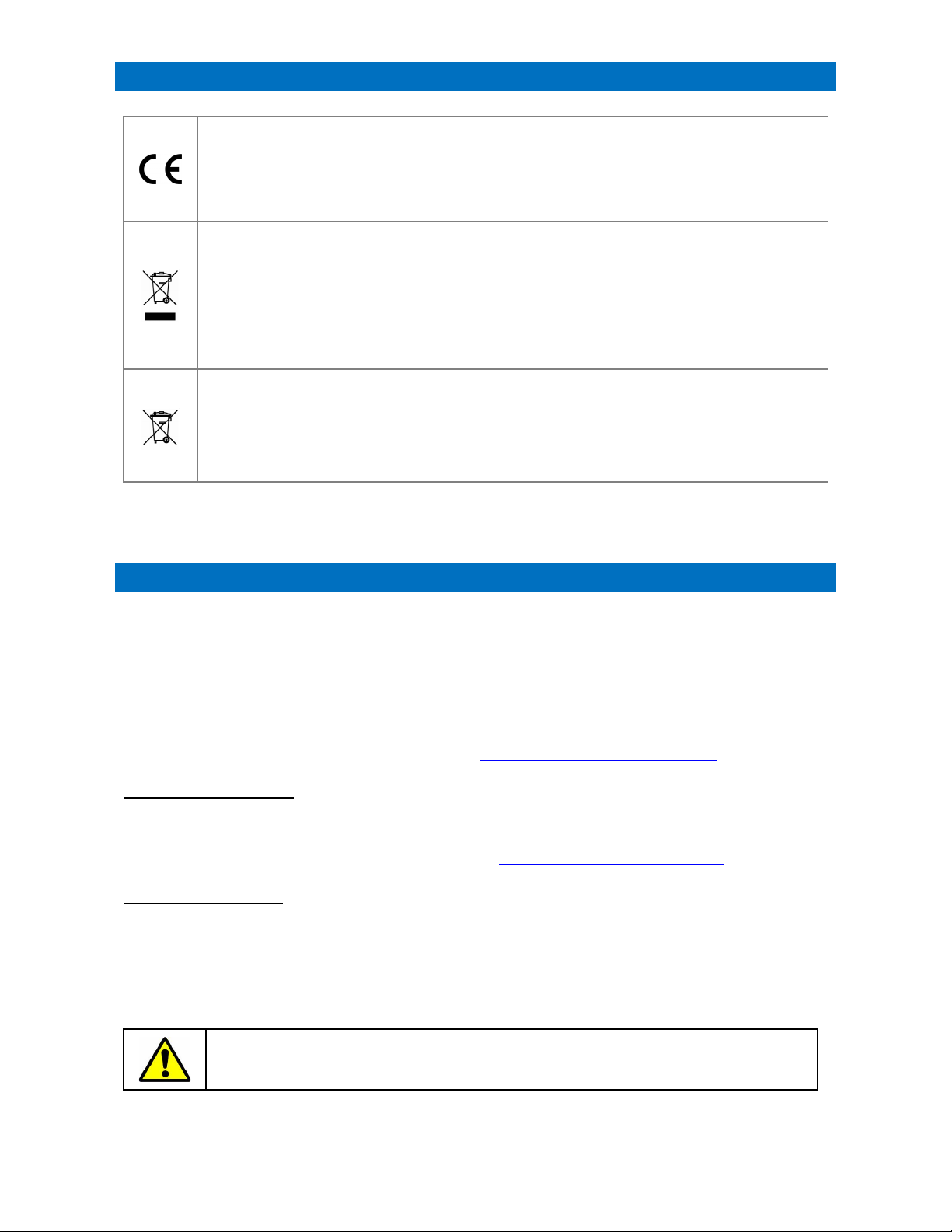
ThissymbolontheproductindicatesitcomplieswithallrelevantEUDirectivesasrequiredbylawe.g.
Radio&TelecommunicationTerminalEquipment(RTT&E),SafetyofInformationTechnology
Equipment(LVD),ElectroMagneticCompatibility(EMC)andRestrictionofHazardousSubstancesRoHS.
SeetheSpecificationforeachindividualproductinsection19onwardsforrelevantApprovals.
AcopyofthecompleteDeclarationofConformityisavailablefromTynetec.
ThissymbolontheproductindicatesitisclassedasElectricalorElectronicEquipmentandshouldnot
bedisposedofwithothercommercialwasteattheendofitsworkinglife.
TheWasteofElectricalandElectronicEquipment(WEEE)Directive(2012/19/EU)hasbeenputinplace
torecycleproductsusingthebestavailablerecoveryandrecyclingtechniquestominimiseimpacton
theenvironment,treathazardoussubstancesandavoidincreasinglandfill.
Forproductdisposalpleasecontactyoursupplierandcheckthetermsandconditionsofthepurchase
contractandensurethisproductisnotmixedwithothercommercialwastefordisposal.
Thissymbolonbatteriesindicatesseparatecollection.Batteriescontainchemicalsthatcanbe
hazardoustohealthandtheenvironmentandshouldnotbedisposedofinthewastebin.
TheEUDirective(2006/6/EC)hasbeenputinplacetoensurethesafedisposalandrecyclingof
batteries.
Returnusedbatteriestoyoursupplierordrop‐offatyourlocalmunicipalwasterecyclingdepot.
NTENTS
4. MAINTENANCE&CARE
ForpeaceofmindandtoensureyoursystemismaintainedtothehigheststandardTynetecrecommendan
annualMaintenanceContract.Thiswillprovidevitalassistanceintimesofneedfromanationwideteamof
trainedServiceEngineerswhospecialiseinwardencallsystems.
APreventativeMaintenanceVisit(PMV)isalsorecommended,thiscoversthereplacementofallbatteries,
afullsystemtest,softwareupdates(whereapplicable)andaServiceCertificate.
FormoreinformationonMaintenanceContractpackagesandPMV’spleasecontactyourlocalTynetec
ApprovedInstaller,alistcanbefoundonourwebsite;www.tynetec.co.uk/installer‐locator
MONTHLYMAINTENANCE
DECTServers,BaseStations,RepeatersandPBX’sdonotrequireanyregularmaintenance,ifaunitshows
signsofexternaldamageitshouldbereplacedimmediatelybyaServiceEngineer.
Productsneedingrepaircanbereturnedviathewebsite;www.tynetec.co.uk/returns‐policy
ANNUALMAINTENANCE
TherechargeablebatteriesintheRepeaterPSU’sandtheUPSshouldbetestedeveryyearbyaService
Engineerandreplacedevery3‐5yearsdependingonthenumberofdischargecyclesandenvironmental
conditions.RechargeablebatteriesintheDECTtelephonesshouldbereplacedevery2yearsor500
chargingcycles.Seethespecificationforeachproductinsection18onwardsfordetailsofbatterytypes.
IntheunlikelyeventthattheDECTsystemneedstobeturned‐offorreset,pleaseensure
allactivecallsareactionedbeforeproceeding.

DocNo.FM0814issue2Page6
5. DECTOVERVIEW
ThemaximumtheoreticalrangeforanyDECTsystemis500metresunderidealconditions,inpracticethe
rangewillrarelyexceed300metresduetoreflectionsfromnearbybuildings,trees,water,etc.
Obstructionsinsidebuildingssuchaswallsandfloorswillreducetherange,someconstructionmaterials
suchasfoilbackedplasterboard,reinforcedconcreteorstonewallswillreducerangefurther.
Environmentalconditionssuchashighlevelsoftransmissionatnearbyfrequenciesoremissionsfromother
electricalequipmentmayalsoreducerange.
Clearline‐of‐sightwillgivemaximumradiocoverage,itisimpossibletostateaspecificindoorrangein
advanceofasitesurvey;however,asaguideyoucanusuallyachieve50metresradiusfromthe
Server/BaseStationorRepeater.
LocatingtheServer/BaseStationashighandfreefromimmediateobstructionaspossiblewillhelpto
maximiseitsrange.EveniftheServer/BaseStationisplacedintheoptimumpositionitmaynotalways
achievecoverageinthemostremotecorners,ifthisisthecasethenadditionalRepeaterswillberequired.
RepeatersaregenerallyplacedinastarconfigurationaroundtheServer/Basestation;however,itis
possibletoextendthecoverageinonedirectionwithupto3repeaterjumps.Asitesurveywillberequired
toestablishthebestDECTsystemandBase/Repeaterconfigurationrequired.
TheServer,BaseStationsandRepeatersshouldalwaysbelocatedatleast5metresawayfromtheAdvent
XT2controller,NTR’soranyotherelectricalequipmenttoavoidtheriskofinterference.
AllDECTproductsmustbesitedinadrysecurearea;theyareNOTsuitableforoutdoorlocations.
AVOID LOCATING DECT PRODUCTS…
WITHIN5METRESOF
OTHERELECTRONIC
EQUIPMENT
DIRECTLYABOVEA
HEATSOURCE
INDIRECTSUNLIGHTNEARTOSPLASHING
WATER
IMPORTANT NOTE:
CaremustbetakenduringinstallationandcommissioningofanyDECTsystemtoensurefullradio
coverageandcorrectRadioPartNumberingofBaseStationsandRepeaters.Failuretofollowthe
Manufacturer’sinstallationandprogramminginstructionsmayresultinblindspotsorcallsdropping‐out
whenmovingbetweenradiocells.Alwaysperformseveraltestcallsinallextremesofthebuildingwithall
DECThandsetsinuse,i.e.simultaneousphone‐phonecalls.
S

DocNo.FM0814issue2Page7
6.RELATEDDOCUMENTATION
ThismanualprovidesgeneralinformationregardingtheinstallationoftheDECTtelephonesystem.
FormoredetailedinformationrefertotheSpectralinkinstallationanduserguides.
SPECTRALINK DOCUMENTS
YoucanrequestcopiesofthedocumentslistedbelowfromTynetec’scustomersupport.
TynetecEngineerscandownloadthemfromtheLegrandDialeg365UKAL&HDocumentLibrary.
AlternativelydownloaddirectfromSpectralink;
https://support.spectralink.com/products?qt‐product_finder_tabs=1&type=All
Spectralink7202/12Handsetquickstartguide
Spectralink7702/12Handsetuserguide
SpectralinkHandsetManagementuserguide
SpectralinkHandsetBatteryinformationguide
SpectralinkHandsetMultiChargerinstallationguide
SpectralinkIntegratorMessagingDiscoverydocument
SpectralinkIP‐DECTServer400/6500installation&configurationguide
SpectralinkIP‐DECTServer400/6500synchronization&deploymentguide
SpectralinkIP‐DECTBaseStationinstallationguide
SpectralinkDECTRepeaterinstallationguide
SpectralinkBaseStationsorRepeaters?
UsethelinkbelowtodownloadtheDECTRepeaterservicetoolsoftware:
https://support.spectralink.com/products/dect/spectralink‐dect‐repeater

DocNo.FM0814issue2Page8
A
B
C
F
E
D
I
H
G
L
K
J
O
N
M
V
U
T
S
R
Q
P
Z
Y
X
W
spectralink
A
B
C
F
E
D
I
H
G
L
K
J
O
N
M
V
U
T
S
R
Q
P
Z
Y
X
W
spectralink
A
B
C
F
E
D
I
H
G
L
K
J
O
N
M
V
U
T
S
R
Q
P
Z
Y
X
W
spectralink
7.SITEWIRINGREQUIREMENTS
IP-DECT 400 SINGLE-CELL SYSTEM
____________________________________________________________________________________
IP-DECT 400 MULTI-CELL SYSTEM
____________________________________________________________________________________
IP-DECT 6500 SYSTEM

DocNo.FM0814issue2Page9
PINNo.Cat5eWIRECOLOUR
1White/Orange
2Orange
3White/Green
4Blue
5White/Blue
6Green
7White/Brown
8Brown
7. SITEWIRINGREQUIREMENTS
IP‐DECTBaseStationsshouldbeconnectedtothePoEPortsonthe
EthernetSwitchusingCat5eRJ45wallsocketsandCat5ePatchLeads.
WirebetweenthewallsocketsusingCat5eEthernetU/UTPcable
(BeldenType:1583E.00B100)orequivalent,AidcallPartNo.YW1731.
Themaximumcablelengthmustnotexceed100metres.Makeall8connections.
WALLSOCKETFROMREAR
DECTRepeatersshouldbeconnectedtothe12V/2ABatteryBackedPSU
using1.0mmTwincable(ordoubled‐uppairsofCW1308).
Connectamaximumof6RepeatersperPSU,themaximum
cablelengthmustnotexceed100metres.
DECTRepeatersaresuppliedwithashortRJ11powerlead;YELLOW=12V&BLACK=0V.
4
5
8
7
3
6
2
1
RJ45WallSocket:
TynetecPartNo.P10280
SurfaceBackbox:
TynetecPartNo.O15090
2mPatchLead:
TynetecPartNo.W00402
2mPatchLead2mPatchLead
Cat5eCable(Max100m)
Makeall8connections
EthernetSwitch
RJ45WallSocket RJ45WallSocket
IP‐DECT
BaseStation
UsePoEPorts
Max6DECTRepeatersperPSU
240V
AC
Use8CoreCableMax100m
BatteryBackedPSU

DocNo.FM0814issue2Page10
8. SPECTRALINK7202/7212DECTHANDSETS
Thedurable,robust,andfeaturerichSpectralink7202/7212DECThandsetsaredesignedtoenable
healthcarepersonneltobemobilewhilestillwithinquickreachincriticalsituations.Furthermore,the
handsetisdustproofandprotectedagainstsplashingwatermakingitsuitableforuseinwetroom
environments.
TheSpectralink7202/7212DECThandsetscomecompletewithadesktopchargerandaUKplug‐toppower
supply(TynetecbundlePartNo’s.ZXT523/ZXT524).
ACCESSORIES & SPARES
RefertotheSpectralink7722/7742Handsetquickstartguideanduserguide(seesection6).
AlarmButton
Loudspeaker
LEDIndicator
ColourDisplay VolumeControl
LeftSoftKeyRightSoftKey
On/OffHookKey
CallTransferKey
4WayNavigationKey
Microphone
HeadsetConnector(7212only)
VibrationAlert(7212only)
Desktop
Charger
UKPlug‐top
PowerSupply
SpectralinkRef.TynetecPartNo.Product
84743428W03051SpareBattery(1170mAh)
02319520W03065SafetyLine
02319701W03066CarryCase
02319597W03067BeltClip
14196110W03068BeltClip/HandsetConnector

DocNo.FM0814issue2Page11
9. MULTICHARGER&PSU
TheoptionalMultiChargerisamodularsystem,eachMultiChargermodulecanchargeupto5Spectralink
7202/7212DECThandsetsatthesametime.Usingtheincludedlinkcable,upto3MultiChargermodules
canbeconnectedtogetherhorizontallyorverticallytoprovidechargingfromonePSU,eliminatingtheneed
for15separatemainssockets,PSU’sandchargers.
TheMultiChargercanbedeskmountedorfixedtothewall.Itispossibletowallmountanunlimited
numberofMultiChargerssimultaneouslyanditispossibletoexpandthenumbersshouldyourneedsgrow.
WiththeMultiChargeryoucanbenefitfromaccesstofullychargedhandsetsatanytime,itiseasytosee
whichhandsetsarechargedandifanyaremissing.
MultiChargerBlocksandPSU’sareorderedseparately,remember;1PSUmodulecanpowerupto3
ChargerBlocks(15handsets).
PART NUMBERS
RefertotheSpectralinkHandsetMultiChargerinstallationguide(seesection6).
PowerSupplyforupto
3ChargerBlocks
Deskorwallmount
MultiChargerBlock
forupto5Handsets
358mmx63mmx63mm
(HxWxD)
LinkCableforconnecting
upto3ChargerBlocks
SpectralinkRef.TynetecPartNo.Product
02509400W03034SpectralinkMultiCharger(Inc.LinkCable)
02509501W03043SpectralinkMultiChargerUKPSU

DocNo.FM0814issue2Page12
10.IP‐DECTSERVER400&IP‐DECTBASESTATION
TheIP‐DECTServer400controlstheIP‐DECTBaseStation(s)andmanagestheIPinterfacetoanoptionalIP‐
PBX.ThecommunicationprotocolbetweentheIP‐DECTServer400andtheIP‐PBXisSIP.TheIP‐DECT
Server400usesthewirelessbandETSI(1880‐1900MHz),referredtoas1G8.
TheIP‐DECTServer400canbedeployedaseitherasingle‐cellormulti‐cellsolution.Thesingle‐celloptionis
easytodeployforasmallscheme,wherethereistheneedformoreusersorcoverageofalargerareathen
themulti‐cellsolutioncanbeusedwithupto3additionalIP‐DECTBaseStations.
TheIP‐DECTBaseStationhas12simultaneoustrafficchannels(32Kbits/s).TheIP‐DECTBaseStation
controlsthetrafficintheairandworksasthelinkbetweentheDECThandsetsandtheIP‐DECT400Server.
IP‐DECT400ServersandBaseStationsarehousedinthesameABSenclosure;alwayschecktheModelNo.
labelontherearoftheunittobesureofwhichproductyouarelookingat;
*theMulti‐cellversionhasanadditionallicenceappliedduringmanufacture
LED INDICATOR
ThefrontcoverStatusLEDwillindicatetheIP‐DECTServer/BaseStationstatusbydifferentcoloursand
flashpatterns,seethetablebelow;
LEDColourMeaning
SteadyGreenOKandidle
SlowGreenFlashingOKandactivevoicecall
FastGreenFlashingBusy(allchannelsinuse)
SlowRedFlashingNoconnectiontoBase
FastRedFlashingError–nooverairsyncpossible
SteadyRedResetinprogress(seeRESETbuttonbelow)
SteadyRedfor5Seconds
thenFastRedFlashingResettofactorysettings(seeRESETbuttonbelow)
WallMountKeyhole
FixingsonRear
StatusLED
SurfaceMountABSEnclosure
100x100x38mm(HxWxD)
8VPSUPort(NotUsed)
ResetButton
EthernetPort(PoE)
GreenFlashingLED=Activity
YellowLED=EthernetOK
SpectralinkRef.TynetecPartNo. Product
02344500ZXT503 IP‐DECTServer400(Single‐Cell)
02344500*ZXT504 IP‐DECTServer400(Multi‐Cell)
02337400ZXT536 IP‐DECTBaseStation
ProductLabel
onRear

DocNo.FM0814issue2Page13
10.IP‐DECTSERVER400&IP‐DECTBASESTATION
RESET BUTTON
YoucanrestartorresettheIP‐DECTServer/BaseStationbypressingtheRESETbuttononthebottomface,
seethetablebelowforthe2possibleactions;
PressButtonAction
Shortpress(2‐5Secs)Server/BaseStationrestartswhenthebuttonisreleased
Longpress(5‐9Secs)untilfrontLED
flashesredthenreleasebutton
Resettofactorydefaults(originalIPsettingandemptyuser
database)andrestart.
INSTALLATION
TheIP‐DECTServer400(Single‐CellandMulti‐Cell),IP‐DECTBaseStationsand2/4ChannelDECTRepeaters
areallhousedinthesametypeofenclosureandhavethesamefixingcentres.
FRONT REAR
AllDECTradiopartsshouldbemountedverticallyonthewallatleast2.4metresabovefloorlevelbutno
higherthan6metres.
TheywillnormallybefittedwiththeEthernet/PowerPortatthebottom;however,theycanbeinverted
withtheEthernet/PowerPortatthetopifdesired.
Donotfixflushontheceilingasthiswillaffectsignalpropagation.
Thekeyholefixingslotsonthebackofallunitsare64mmapart,fixingscrewsandwallplugsareprovided.
Youcanfindafixingtemplateonthecentrepagesoftheproductinformationbookletinthebox.
RefertotheSpectralinkIP‐DECTServer400/6500installation&configurationguideandIP‐DECT
BaseStationinstallationguide(seesection6).
100mm
100mm
Ethernet/PowerPort
64mm
28mm
spectralink
02337400
Server/BaseStationDepth:38mm
RepeaterDepth:29mm
Status
LED

DocNo.FM0814issue2Page14
11.IP‐DECTSERVER6500
TheIP‐DECTServer6500controlsthewirelessinfrastructure;itmanagesMediaResources,BaseStations,
RepeatersandtheIPinterfacetotheMatrixIP‐PBX.ThecommunicationprotocolbetweentheIP‐DECT
Server6500andtheIP‐PBXisaSIPlineinterface.
TheIP‐DECTServer6500providestheDECTsolutionforalargegeographicalareaand/oralargenumberof
mobileusers.ThemodularnatureoftheIP‐DECT6500Servermakesiteasytoincreasethenumberofvoice
channelswiththeMediaResourceand/orgeographicalcoveragewithadditionalIP‐DECTBasestations.
SYSTEM CAPACITY
MaxNo.ofIP‐DECTBaseStations:512
MaxNo.ofsimultaneouscallsoneachIP‐DECTBaseStation:11
MaxNo.ofRepeatersoneachIP‐DECTBaseStation:3
MaxNo.ofMediaResources:32
MaxNo.ofsimultaneouscallswith1MediaResource:32
MaxNo.ofsimultaneouscallswith32MediaResources:1024
MaxNo.ofDECThandsets:scalableto4095(stepwise30/150/500/1500/4095users)
RefertotheSpectralinkIP‐DECTServer400/6500installation&configurationguide
(seesection6).
19”RackMountSteelEnclosure
440x199x44mm(WxDxH)

DocNo.FM0814issue2Page15
12.DECTREPEATER
DECTRepeatersareusedtoextendthewirelesscoverageareainaDECTnetwork.TheDECTRepeater
providesalargergeographicalspreadofthetrafficchannelsandincreasesthecoverageareabutitdoes
notincreasethenumberofchannelsavailable.TheDECTRepeaterisnormallyusedinareaswithlimited
coveragee.g.longhallways,stairwellsandcorridors.
DECTRepeatersareavailablewitheither2or4voicechannels.TheRepeateriswirelesswithnoconnection
totheDECTServerorBaseStation;however,itdoesneedconnectiontoabatterybackedpowersupply.
2Channeland4ChannelDECTRepeatersarehousedinthesameABSenclosure;alwayschecktheModel
No.labelontherearoftheunittobesureofwhichproductyouarelookingat;
LED INDICATOR
ThefrontcoverStatusLEDwillindicatetheRepeaterstatusbydifferentcoloursandflashpatterns,seethe
tablebelow;
LEDColourMeaning
SteadyGreenOKandidle
ShortGreenFlashOKandactivevoicecall
FastGreenFlashingBusy(allchannelsinuse)
FastRedFlashingError–nooverairsyncpossible
RESET BUTTON
YoucanrestartorresettheRepeaterbypressingtheRESETbuttononthebottomface.
RefertotheSpectralinkDECTRepeaterinstallationguideandServiceToolsoftware(for
Windows)forprogrammingRepeaters(seesection6).
SpectralinkRef.TynetecRef. Product
02441100ZXT512 2ChannelMulti‐CellRepeater
02334601ZXT544 4ChannelMulti‐CellRepeater
WallMountKeyhole
FixingsonRear
StatusLED
SurfaceMountABSEnclosure
100x100x30mm(HxWxD)
PSUPort
ResetButton
ProductLabelonRear

DocNo.FM0814issue2Page16
13.DECTREPEATERPSU
The12V/2ABoxedPSU(TynetecPartNo.W00525)requiresconnectiontothemainssupply.
INSTALLATION
Undothelidfixingscrewandopenthelid.
Note:ifthelidisremovedensuretheSafetyEarthisre‐connected.
Fixthepowersupplyunittothewallusingthe3holes“A”asshownbelow.
Connectthemainssupplytothemainsterminalsusingthecolourcode
inthetablealongside.
PSU FIXING
ThePSUshouldonlybeopenedduringinstallationandservice–thelidmustbescrewed
shutatallothertimestopreventtheriskofelectricshock.
NeverleavealivePSUunattendedwiththelidopen.
WallMountedEnclosure
200x230x80mm(HxWxD)
GreenPowerLED
RedFaultLED
BoxedPSU
Hinged/RemoveableLid
MainsConnection
ColourTerminal
BrownL
BlueN
Green/YellowE
160mm
65mm
145mm
A
AA
12V/1A Boxed PSU
E
N
L
O/P
+‐
PSU LED INDICATORS
TheGREENPOWERLEDshouldbe
permanentlyilluminatedwhenthe
Mainssupplyishealthy.
TheREDFAULTLEDwillilluminate
ifthe12Voutputfusehasblownor
thebatteryPTCresettablefusehas
tripped.
95mm
BatteryBacked
12V/2ABoxedPSU

DocNo.FM0814issue2Page17
13.DECTREPEATERPSU
BATTERY REPLACEMENT
The12V/2ApowersupplyunitprovidedfortheRepeatersincludesa12V3.4Ahrechargeablebattery.
Thisbatterywillmaintainnormaloperationforseveralhoursintheeventofamainspowerfailure.
TherechargeablebatteryshouldberemovedandtestedbyaServiceEngineeronanannualbasisand
replacedevery3‐5years.
Withthebatterydisconnected;checkthechargevoltageacrossthebatteryleadsisbetween13.6VDCand
14.2VDC(13.8Vnominal).
Ifthebatteryshowsanysignsofdamage,swellingorleakageduringanannualinspectionitshouldbe
replacedimmediately.
OnlyreplacewiththeManufacturersApprovedbatterytype:
YuasaNP3.4‐12:12V3.4AhSealedLeadAcidRechargeableBattery
ReplacementbatteriesareavailablefromTynetec;orderPartNo.F00040
IMPORTANT:alwaysmarkthebatterywiththedateitwasreplacedforreferenceonfutureServicevisits.
Seesection3ofthismanualforRegulationsregardingthesafedisposalofusedbatteries.
12VDC2A
PowerSupply12V3.4AhLeadAcid
RechargeableBattery

DocNo.FM0814issue2Page18
14.MATRIXIP‐PBX
TheMatrixEternityNE312isapowerfulIP‐PBXplatformbasedonamodulararchitectureoffering3CO
(TWT)analoguetrunksforaccesstotheoutsideworld,8IPextensionsand12analogueSingleLine
Telephoneextensions.ThenumberofIPextensionscanbeincreasedto16withanadditionalLicence.
IP-PBX CONNECTIVITY
IconRef.TynetecRef. Product
NE312EUZXT556 MatrixEternityNE312IP‐PBX(8IPPorts)
NE312EU+NE‐IP8ZXT557 MatrixEternityNE312IP‐PBX(16 IPPorts)

DocNo.FM0814issue2Page19
15.IP‐DECT400SINGLE‐CELLSYSTEMINSTALLATION
TheIP‐DECTServer400single‐celloptionissuitableforsmallinstallationsusing1Server/BaseStationand
upto6Repeaters.Upto12DECThandsetscanbeusedonasingle‐cellsystem.
SeeTynetecDrgNo.ZXT900sheet7fordetailedconnections
PART NUMBERS
PartNo.DescriptionNotes
ZXT548700VAUPS1persite
ZXT556MatrixEternityIP‐PBX(8IPPorts)1persite(useZXT557
for9+DECTHandsets)
ZXT557MatrixEternityIP‐PBX(16IPPorts)
ZXT502PoEInjector1persite
ZXT503IP‐DECTServer400(Single‐Cell)1persite
ZXT5122ChannelMulti‐CellRepeatermax6persite
ZXT523Spectralink7202DECTHandset
&
Charger max12persite
ZXT524Spectralink7212DECTHandset&Charger
ZCS766CLIDeskTelephone1persite
ZCS729RepeaterProgrammingKit1offpurchase
W0052512VDC2ABoxedPSU1persite
F0004012V3.4AhRechargeableBattery 1perPSU
UPS CONNECTION
TomaintainDECToperationduringamainsfailuretheMatrixIP‐PBXandPoEinjectormustbothbe
poweredfrombatterybackedoutputsocketsontheUPS.
Note:IftheMatrixIP‐PBXandPoEinjectorarepluggeddirectlyintothemainstherewillbenoDECT
coverageduringamainsfailure;however,theCLIdesktelephonewillstilloperate.
PoE INJECTOR CONNECTION
ThePoEinjectorprovidesPoweroverEthernetfortheIP‐DECTServer400(Single‐Cell).
POWER‐connecttoabatterybackedoutputsocketontheUPSusingthemainsleadprovided.
ETHERNET‐connecttotheMatrixIP‐PBXEthernetPortusinganRJ45patchlead.
ETHERNET&PoE‐connecttotheIP‐DECTServer400usinganRJ45patchlead.Thisconnectioncanbe
extendedtoamaximumof100metresusingCat5ecable.
DECTHandsets(max12)
2ChannelMultiCellRepeaters
240V
AC
240V
AC
BatteryBackedPSU
PoEInjector
Matrix
IP‐PBX
CLIDeskTelephone
OfficeTelLine
AdventXT2Line1
Re
p
eaters(max6)
700VA
UPS
IP‐DECT
Server400
(Single‐Cell)
AdventXT2Line2

DocNo.FM0814issue2Page20
15.IP‐DECT400SINGLE‐CELLSYSTEMINSTALLATION
MATRIX CONNECTION
TheMatrixIP‐PBXinterfacestheAdventXT2totheDECTequipment;italsogivesaccesstoanoutsideline
andallowszoningofcalls.
24VDC‐connecttotheUPSviathein‐linePSUmoduleprovided.
CO1‐connecttotheAdventXT2DECT1outputusingtheRJ11/BTleadprovided.
CO2‐connecttotheAdventXT2DECT2outputusingtheRJ11/BTleadprovided.
CO3‐connecttoanexternaltelephonelineusingtheRJ11/BTleadprovided.
SLT1‐connecttotheCLIdesktelephoneviaaBTmastersocket(cutplugofftheRJ11/RJ11leadprovided).
ETHERNET‐connecttothePoEinjectorusingtheRJ45patchleadprovided.
TheMatrixmusthaveitsIPaddresssetto192.168.0.2,it’sfactoryprogrammedsoallincominglinesringall
extensions.IfanincominglineistoringspecificextensionsthentheMatrixmustbereconfigured.
Note;intheeventofamainsfailurei.e.iftheUPSbatteriesrunflatorifaUPSisnotfitted,theMatrix
connectsCO1toSLT1andtheAdventXT2willonlyringtheCLIdesktelephone.
IP-DECT SERVER 400 (SINGLE-CELL) PROGRAMMING
TheIP‐DECTServer400musthaveitsIPaddresssetto192.168.0.3anditsRadioPartNumbersetto3.
Refertothemanufacturersinstallationguideforfullinstructions‐seesection6.
ADVENT XT2 PROGRAMMING
ThePBXRingTypemustbeenabledintheAdventXT2programming–seetheOnsite&GeneralSetup
sectionoftheAdventXT2programmingmanual(DocNo.FM0815).
2 CHANNEL MULTI CELL REPEATERS
Amaximumofsix2ChannelMulti‐CellRepeaterscanbeusedwiththeIP‐DECTServer400Single‐Cell.
Repeatersrequireapowerconnectiononly;theycommunicatewiththeServervialowpowerradiosignals
anddonotrequirealineconnection.TomaintainDECTcoverageduringamainsfailureallRepeatersmust
beconnectedtoabatterybacked12VDCPSU.
REPEATER POSITIONING
BeforeinstallingpowercablestoRepeaterpositions,itisimportantthattheoptimumpositionforcoverage
isestablished.RegistertheRepeaterontotheIP‐DECTServer400thenwiththeRepeaterpoweredfroma
batterywalkawayinthedirectionthatcoveristobeextended.WhentheredLEDontheRepeaterstartsto
flashitisoutofrangeandmustbemovedbacktowardstheServerbyaminimumof5metresbefore
selectingitsfinallocation.TheLEDshouldbesteadygreen.SeeRepeaterDeploymentRulesonthe
followingpage.
REPEATER PROGRAMMING
Refertothemanufacturersinstallationguideforfullinstructions–seesection6.Aprogrammingkit(P/No.
ZCS729)isrequiredtoprogramRepeaters,theServiceToolsoftwarecanbedownloadedviathelinkin
section6ofthismanual.
REPEATER POWER CONNECTION
Repeatersshouldbeconnectedusing1.0mmpaircabling,ifCW1308isbeingusedthensparepairscanbe
doubled‐upand/orloopedbacktoformaringcircuittoreducethevoltagedropifnecessary.
Maximum6x2ChannelMultiCellRepeaters
240V
AC
BatteryBacked12VDCPSU
RepeaterPowerLeadColourCode
YELLOW=12VBLACK=0V
Use1.0mmCableMax100m
Other manuals for Advent XT2
2
Table of contents