Tytan DS 512 User manual

Vehicle Security System
GSM/SMS Pager
DS 512 - CAN GSM GPS
INSTALLATION MANUAL
ver. 0.14

2
tytan
TYTAN DS512 CAN GPS GSM
CAN-bus Vehicle Security System (VSS) and GSM-SMS Pager features
• GSM-SMS pager integrated with CAN-bus Vehicle Security System central unit,
• alarming state signalisation with SMS messages in GSM network,
• external GPS receiver (optional),
• remote (SMS) control of VSS and remote access to VSS trigger source memory,
• valet mode (service mode),
• operation mode as GSM-SMS Pager monitoring for OEM security system via CAN bus,
• operation mode as GSM-SMS Pager monitoring for any analogue security system already
installed in the vehicle,
• operation mode as independent Vehicle Security System with CAN-bus connection
to vehicle electronic systems is armed/disarmed with OEM remotes or SMS commands,
• VSS: control by additional Tytan remote transmitters (optional - only with external RF
module),
• VSS: signalisation if door / trunk / bonnet is open during arming (door ajar),
• VSS: signalisation if the alarm was triggered during disarming,
• VSS: analogue control of central door locking and power windows (optional - only with
external RF module),
• VSS: CAN-bus control of hazard lights, central door locking, power windows on some
• VSS: additional sensors input
- vehicle interior protection with ultrasonic motion detector (optional),
- vehicle towing and wheel theft protection with additional tilt sensor (optional),
• VSS: arming without additional sensors,
• VSS: state of the system is stored in non-volatile memory and is saved during power-off,

Digital Systems
3
GENERAL
•Tytan DS512 was designed to use in all vehicles with 12V/24V power supply system and
negative ground.
•Tytan DS512 must be installed according to the manufacturer’s requirements and
documentation.
•It is suggested to install the DS512 only by an authorized person or company. The list
of authorised installers can be obtained from manufacturer or distributor of Tytan DS512
CAN. It should be checked, if the installation certificate, delivered with the system has been
filled in by the installer.
•The system is compatible with CAN-bus networks in most modern vehicles. In order
to work properly, before installation, the VSS central unit has to be programmed for a given
make and model of car.
•The installer must fulfil all the general requirements concerning safety at work during car
service procedures.
•Before installing the DS512 the negative terminal of the battery must be disconnected.
If for some reasons disconnecting the battery is impossible, during the installation the cable
loom must be disconnected from VSS central unit.
•All the connections must be insulated, the wires must be protected against abrasion
to prevent any short circuit the vehicles electronics.
•The installed DS512 central unit must not be exposed for contact with water, petrol,
grease, oil, and other chemical substances. It is suggested to place the unit in a well hidden
place inside the car, preferably under the dashboard.
•The siren should be installed in engine chamber in a place, that provides protection from
extensive dirt and direct flow of water.

4
tytan
1. DS512 OPERATING PRINCIPLE
The DS512 is a device, that combines function of a complete Vehicle Security System (VSS)
and the SMS pager.
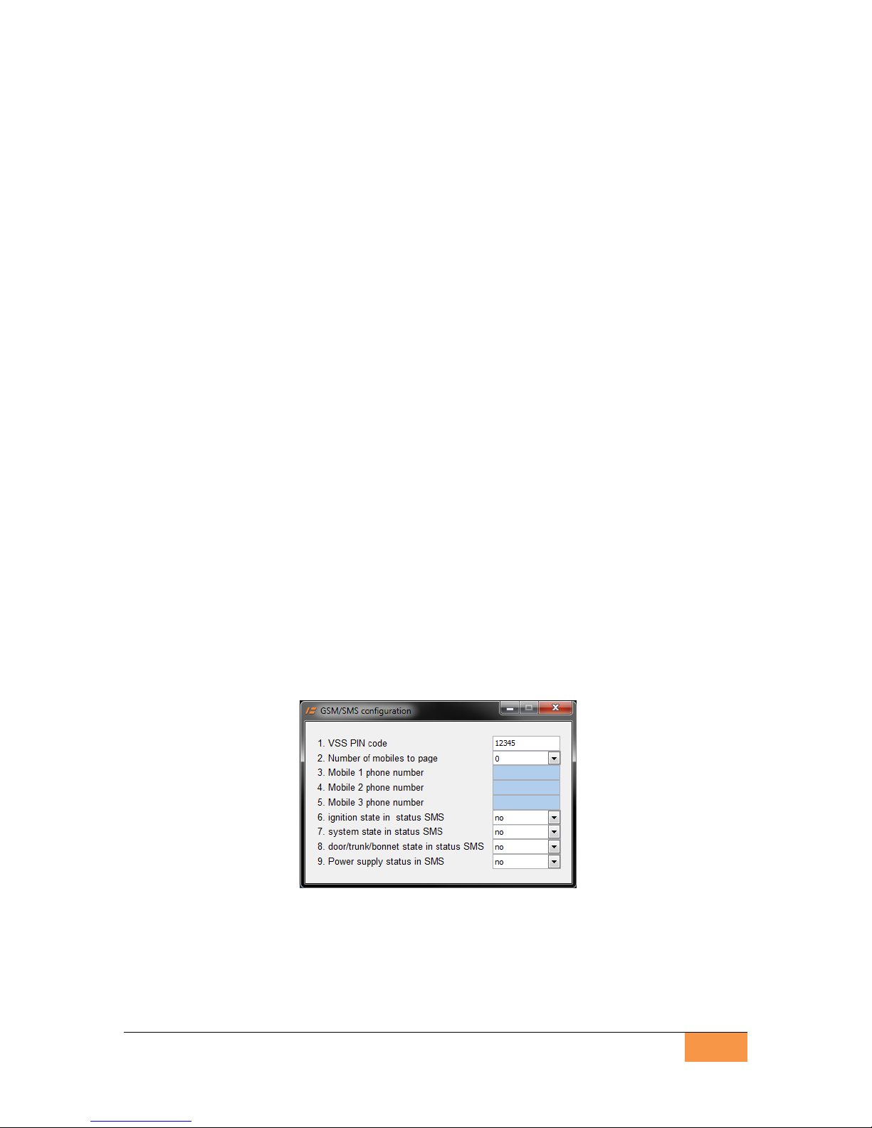
The general purpose of DS512 is to notify up to 3 mobile phone numbers with SMS
information containing status of vehicle and status of equipped security system.
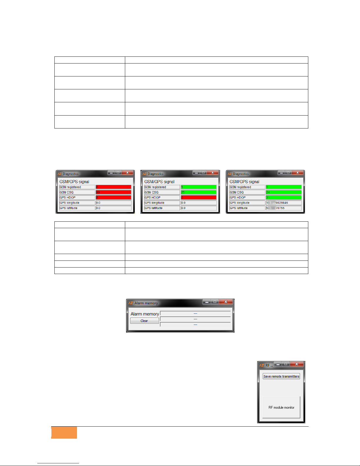
The DS512, can be equipped with external GPS receiver. This allows to receive vehicle
geographical position in the form of latitude and longitude. SMS notification also includes
a link to online maps, which can be opened in any web browser to visualise vehicle position.
The localisation of the vehicle is set only when the alarm is triggered or if the dedicated SMS
command protected by individual VSS PIN is sent to the VSS (see user manual).
The DS512 can work without alarm function (VSS) - without optical and acoustic signalisation
of alarming. The device works as a SMS pager that monitors third party VSS, already
installed in the vehicle.
The 4 modes of DS512 operation are described below:
DS512 operating modes:
Mode 4 - FULL ALARM - complete CAN-bus VSS with audible and visible signalisation.
DS512 is the complete vehicle security system, controlled by OEM remote or Tytan remotes,
integrated with the vehicle via CAN bus.
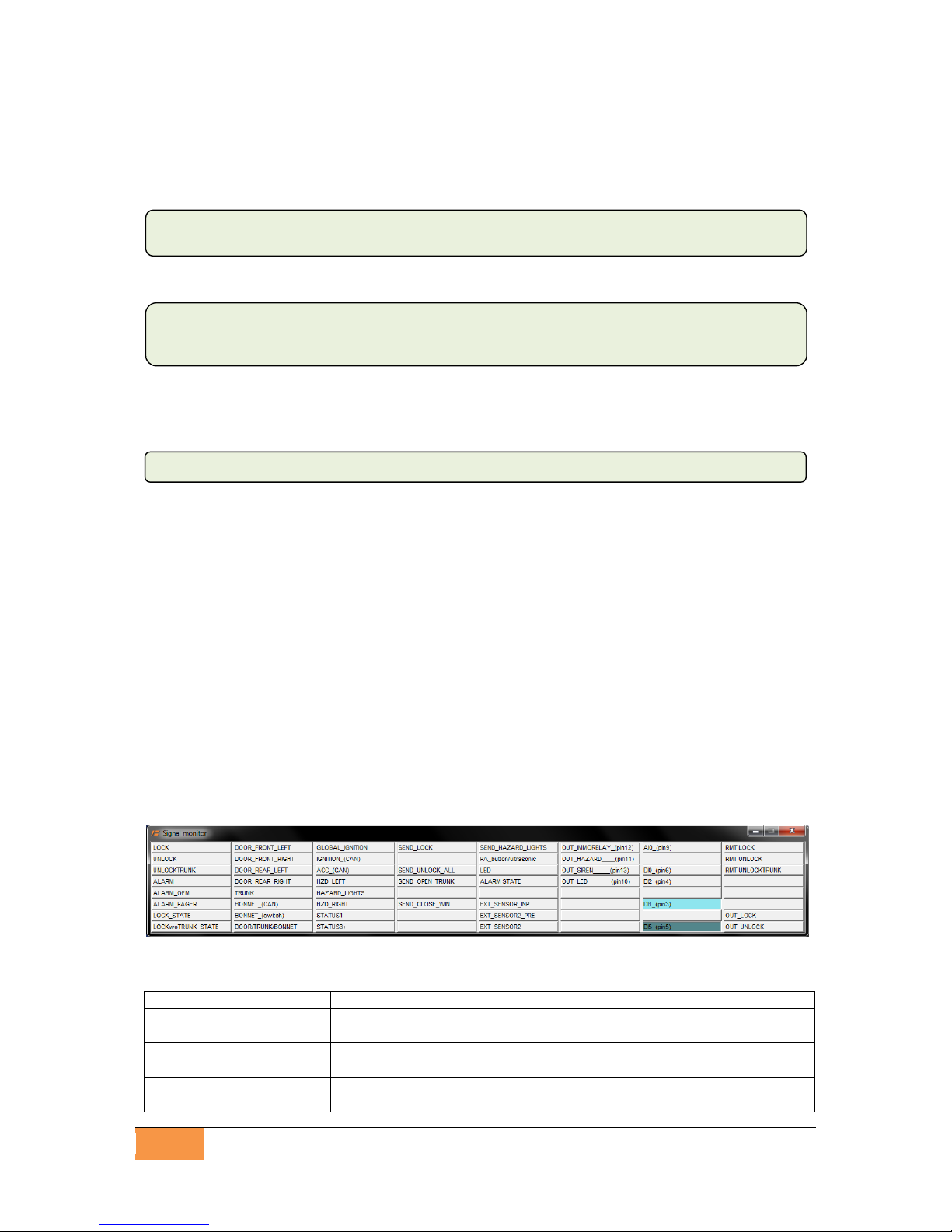
In this mode the DS512 monitors the doors, trunk, bonnet and optional additional sensors
or OEM alarm system. When the device is triggered the acoustic (siren) and visible (hazard
lights) signalisation is started and a SMS notification is being sent. Moreover, triggering
of OEM alarm (for example by OEM internal movement sensor) also triggers the DS512. The
door, bonnet, trunk, ignition and remote control signals are read from CAN bus (in some cars
bonnet and trunk can-bus signals may not be available). Siren output is negative. The hazard
lights negative output can control the hazard lights switch (perimeter connection) or can
control the relays of analogue connections to hazard lights bulbs. The immobilisation NC
relay is controlled by negative output. The vehicle is immobilised when the VSS is armed and
the ignition is switched on.
The DS512 can be equipped with optional RF module (radio frequency module),
which allows to control the VSS with additional Tytan remote transmitters. The
receiver module has 2 outputs, for analogue control of central door locking (if Tytan
remote transmitter is used) and for analogue power windows control (any remote
transmitter is used).
The proper wiring diagram is diagram 1.
Mode 3 - SILENT ALARM - CAN VSS without audible and visible signalisation.
The DS512 operates as in mode 4, but the audible and visible signalisation is disabled. The
engine immobilisation operates as in mode 4. The appropriate wiring diagram is diagram
1, but without siren and hazard lights connection.
Mode 2 - OEM CAN-bus VSS PAGER
The DS512 works as a Pager, monitoring OEM VSS via CAN bus. Detection of alarming
in the monitored VSS causes the DS512 to page up to 3 users with a SMS about alarming.
There is no audible nor visible signalisation in this mode. The device does not react
on opening the door or switching on the ignition as long as it does not trigger the OEM alarm.
The proper wiring diagram is diagram 2.

Digital Systems
5
Mode 1 - ANALOGUE PAGER
The DS512 operates as an analogue pager to any VSS installed in the vehicle. Detection
of alarming in the monitored VSS causes the DS512 to notify up to 3 users with a SMS about
alarming. There is no audible nor visible signalisation in this mode. The device does not react
on opening the door or switching on the ignition as long as it does not trigger the OEM alarm.
The information on triggering alarm is read from analogue signal. The possible triggering
conditions are: positive signal NO, positive signal NC, ground signal NO, ground signal NC.
The signal must be at least 1 sec. long, in order to ignore short siren chirps if the DS512
is connected to the siren circuit.
If minimal connection of just the triggering circuit is used - the proper wiring diagram
is diagram 3.
Moreover, in this mode, analogue connections of DS512 can be done to ignition circuit, door
signal and the VSS status signal. If these connections are done, the DS512 can give the user
full status of the vehicle (door/ignition/lock state).
If the extended connection of the additional signals is used, the proper wiring diagram
is diagram 4.
Remote stop / anti-hijack function.
In the countries, where the Reg. 97 ECE does not apply, in all the operating modes
described above, the DS512 anti-hijack function can be set.
The anti-hijack sequence is triggered by the SMS protected by a individual VSS PIN.
The anti-hijack sequence involves optical and acoustic signalisation, and after several tens
of seconds the vehicle is stopped. The immobilisation relay is active despite the status
of ignition.
In order to have the acoustic and visible signalisation during anti-hijack / remote stop
procedure in modes 1, 2 and 3 the siren and hazard lights connections must be done. These
connections are presented in the diagram 5.
In order to have operational remote stop function in modes 1 and 2 the immobiliser relay
must be connected. These connection is also presented in the diagram 5.
2. DS512 configuration
The DS512 will operate in the vehicle only if it has been properly configured.
The configuration is made with a dedicated PC software and the mini USB cable.
The software panel has the list of programmable parameters and few buttons, described
below.
- Read loads the configuration from DS512 and shows the settings from the device on the
panel.
- Write saves the parameter values shown in the panel do the device.

6
tytan
Parameter list:
2.1. Operating mode
The parameter selects the operating mode of DS512 as described above (analogue pager
/ CAN-bus Pager / Silent Alarm / Full Alarm).
2.2. Selection of vehicle type
In order to operate correctly with the vehicle CAN-bus in CAN-bus based modes (2,3,4),
the DS512 has to be programmed to a given vehicle model with so-called ‘CAN level’. The
CAN-bus level can be selected according to the table or the wiring diagram for a given
vehicle. Moreover, it can be selected automatically, by choosing make and model of the
vehicle from the list. The list is shown when the ‘make and model’button is pressed.
2.3. Gray wire active signal (pager/door input)
In modes 3 and 4 this wire operates as an alarm triggering input, dedicated for connection
of additional analogue bonnet switch. In mode 1 (pager mode) this wire operates
as an alarm-sensing input dedicated for detection of alarming state.
The active signal of gray wire for all modes can be programmed. The line can sense ground
or positive signal. In case of ground sense - the internal pull-up in DS512 is activated.
In case of positive signal sense, the internal pull-down is activated. Moreover, the line can
react on applying the signal or lack of signal, thus the NO and NC signals can be handled.
For example in NC- mode:
- the input is inactive as long as the ground signal is applied to the input.
- the input is active as long as s the ground signal is not applied to the input.
2.4. Hazard lights
The recommended method of hazard lights connection is ‘perimeter mode’- connection
of dedicated DS512 active ground output (pin11 pink-black wire) to hazard lights switch
circuit.
DS512 can also control the bulb circuits with analogue high current connection. In such case
the hazard lights connection should be set to ‘analogue’and additional relays controlled
by pink-black wire must be used - see diagram 1.
2.5. CAN-bus vehicle control.
On some vehicles the DS512 can perform a CAN-bus control of:
- hazard lights (in this case the analogue or perimeter connection is not required),
- power door locks,

Digital Systems
7
- power windows.
The information which vehicles allow for CAN bus control and which circuits can be activated
is present on the vehicle list and on wiring diagrams
2.6. Audible confirmation of arming/disarming
The parameter enables acoustic signalisation of arming/disarming VSS with short siren
chirps.
IMPORTANT! Audible confirmation can be enabled only in countries where the Reg. 97
does not apply. In opposite case, the homologation of DS512 as a VSS becomes
invalid.
2.7. Power windows roll-up
The parameter enables power windows roll-up when the system is armed. In order to operate
correctly in vehicles with CAN bus power windows control, the necessary level in parameter
5 –CAN-bus vehicle control –must be set.
2.8. Anti-hijack / remote stop enabled
The parameter enables the possibility to initiate anti-hijack sequence - execute remote
vehicle stop via SMS.
IMPORTANT! anti-hijack / remote stop can be enabled only in countries where the Reg.
97 does not apply. In opposite case, the homologation of DS512 as a VSS becomes
invalid.
2.9. GPS receiver
The DS512 can operate as SMS Pager without vehicle localisation or with vehicle
localisation. For vehicle localisation the external GPS receiver must be connected and
enabled.
3. SMS/GSM Paging parameters setup
Press the GSM/SMS settings button to open the configuration window. The panel allows
to set: VSS PIN, number of mobile phones to notify with SMS when alarming, mobile phones
numbers and information details to be placed in status SMS.
VSS PIN - is a 5 digit PIN code protecting the DS512 against unauthorised access by SMS
commands. The commands are described in DS512 User manual.
Up to three mobile number phone numbers can be set to receive the SMS alarm trigger
notifications from DS512. The numbers should be written in international format with
the ‘+’or ‘0’at the beginning, e.g. +44555778899.
The status SMS is sent when the DS512 detects an alarm and as a response to most
of SMS commands.

8
tytan
Depending on the configuration of parameters 6,7,8, the information on ignition state,
combined door/trunk/bonnet state and armed/disarmed state will or will not be included in the
SMS sent from DS512.
If parameter 7 is set to ‘no’ the information on system status will be sent only as:
If it is set to ‘yes’, the information on system status will be more detailed:
Moreover, even if the alarm is not triggered at the moment, but the alarm was triggered
at least once since the vehicle was armed, the additional information will be placed in the
SMS:
In DS512 operating modes 2,3,4, (CAN based), the recommended setting for parameters
6/7/8 is ‘yes’.
In DS512 operating mode 1 (analogue pager) - diagram 4 - the setting ‘yes’ should be set if:
- parameter 6 (ignition) - orange wire (pin6) is connected to vehicle ignition switch circuit.
- parameter 7 (detailed status) - blue wire (pin4) is connected to the ‘armed’signal
of monitored VSS - the wire that is connected to GND if the VSS is armed.
- parameter 8 (door/trunk status) - blue wire from the additional sensors connector (pin5)
is connected to the active ground inputs of monitored VSS as presented in diagram 4.
IMPORTANT! VSS PIN and mobile phone numbers can be programmed later by the
user with a dedicated SMS command.
4. DIAGNOSTIC TOOLS
Press the Signal Monitor button - the panel visualising the CAN-bus and analogue
input/output signals with the indicators will be opened.
Columns 1-5 show the logic input/output signals - if the indicator lights up, it means that the
signal is active.
Lamp
Description
LOCK
Locking the vehicle with OEM remote or with SMS command was
detected. Locking command arms the VSS.
UNLOCK
Unlocking the vehicle with OEM remote or with SMS command was
detected. Unlocking command disarms the VSS.
UNLOCKTRUNK
Trunk release with OEM remote has been detected. It disables trunk,
rear door and additional sensor vehicle protection if the VSS is armed.
ALARM in progress! / ready / valet mode / ANTI-HIJACK in progress! /
ANTI-HIJACK vehicle stopped
disarmed / armed / armed w/o sensors / armed w/o trunk and sensors /
ALARM in progress! / disarmed (rearming) / valet mode / ANTI-HIJACK in
progress! / ANTI-HIJACK vehicle stopped
ALARM was triggered!

Digital Systems
9
ALARM
The DS512 in mode 3 and 4 (operating as VSS) has detected alarm
condition and is alarming.
ALARM_OEM
The DS512 has detected, that OEM CAN VSS has been triggered
(modes 2,3,4) .
ALARM_PAGER
The DS512 has detected, that monitored analogue VSS has been
triggered and is alarming (mode 1 - analogue Pager) .
LOCK_STATE
VSS system is armed / vehicle is locked.
LOCK_woTRUNK
VSS system is armed without trunk, rear door, additional sensor - the
3rd button on remote has been used.
DOOR (...)
Door is opened.
TRUNK
Trunk is opened.
BONNET (CAN)
Bonnet is opened - signal from OEM switch read from CAN-bus.
BONNET (switch)
Bonnet is opened - analogue signal read via gray wire(pin4) in modes (3
and 4).
DOOR/TRUNK/BONNET
The lamp signals if any input is triggered. If the lamp is on, the door
status in SMS is sent as opened, In mode 1 (analogue pager) that lamp
shows the status of monitored VSS inputs.
GLOBAL_IGNITION
The result of ignition signal - the sum of signals from CAN-bus and
analogue signal (orange wire).
IGNITION (CAN)
Ignition switch signal read from CAN-bus.
ACC (CAN)
ACC (ignition switch in accessory position) signal read from CAN-bus.
HZD_LEFT, HZD_RIGHT,
HAZARD LIGHTS
Direction indicators and hazard lights status.
STATUS1-
Status of additional analogue ground signal connected to blue wire (pin
4), necessary for CAN-bus connections on some vehicles (e.g. Renault
Clio).
STATUS3+
Status of additional positive analogue signal connected to orange wire
(pin 3), necessary for CAN-bus connections on some vehicles (e.g.
Subaru Forester).
SEND LOCK,
SEND UNLOCK,
SEND UNLOCKTRUNK
SEND HAZARD LIGHTS
SEND CLOSE WIN
The lamps show that DS512 is sending CAN-bus commands to the
vehicle, that control the vehicle circuits (power door locks, hazard lights,
power windows).
PA button / ultrasonic
The lamp show that the PA button is pressed or the additional sensor
input is triggered.
LED
The lamp repeats the LED state.
ALARM STATE
Device is in alarm state - it is alarming or there was an alarm since last
arming
EXT_SENSOR_INP
Additional sensor input is active
EXT_SENSOR2_PRE
The lamp shows that additional sensor No2 Prealarm input was
triggered.
EXT_SENSOR2
The lamp shows that additional sensor No2 Alarm input was triggered.
Columns 6-7 show the status of device analogue inputs / outputs.
Lamp
Description
OUT_IMMORELAY
The lamp shows that the immobilisation relay output is active -
connected to ground.
OUT_HAZARD
The lamp shows that the hazard lights control output is active -
connected to ground
OUT_SIREN
The lamp shows that the siren control output is active - connected to
ground
OUT_LED
The lamp shows that the LED control output is active - connected to
ground
AI0 (pin9),
DI0 (pin6), DI2 (pin4),
DI1 (pin3), DI5 (pin5),
The lamps show the physical state at the given input. The lamp lights up
if the voltage at the input is positive. That is why the PA button and
STATUS1- inputs, which do have internal pull-up are displayed as
active.

10
tytan
Column 8 shows the status of optional equipment: RF module with analogue central door
lock control outputs and external sensor No2 inputs
Lamp
Description
RMT_LOCK
The lamp shows that LOCK button on Tytan remote transmitter was
pressed
RMT_UNLOCK
The lamp shows that UNLOCK button on Tytan remote transmitter was
pressed
RMT_TRUNK
The lamp shows that UNLOCK_TRUNK button on Tytan remote
transmitter was pressed
OUT_LOCK
The lamp shows that the central door locking analogue control output on
RF module is active - connected to ground
OUT_UNLOCK
The lamp shows that the central door unlocking analogue control output
on RF module is active - connected to ground
Press the GPS/GSM Signal button to open the panel with GSM signal strength (CSQ), the
information if the GSM is registered in the GSM network, GPS signal quality (HDOP) and
GPS data: latitude and longitude. The green colour shows the values which are correct for
the device to operate; red colour shows the values which are insufficient for the device
to operate correctly.
Parameter
Description
GSM registered
Value 1 means that the device is correctly registered in the GSM
network.
GSM CSQ
GSM signal strength. Value 0 is weakest. Value 31 is strongest. Value
99 means no signal. Value >5 is sufficient
GPS HDOP
GPS signal quality. Value <35 is sufficient
GPS longitude
GPS position: longitude
GPS latitude
GPS position: latitude
Press the Alarm Memory button. The panel with alarm memory displays last 3 alarm trigger
sources. The memory can be cleared by pressing the ‘Clear’ button.
If the DS512 is equipped with optional RF module, press the RF module button. The test
panel with 2 controls is opened.
The Save remote transmitters button starts programming procedure of Tytan remote
transmitters.
The RF module monitor control confirms reception of transmission from
all remote transmitters programmed into RF module. After receiving
transmission from any remote transmitter, the control lights up red for a
second and number of the remote in the RF memory is presented.
Moreover, the controls from the eight column (RMT_LOCK,
RMT_UNLOCK, RMT_UNLOCK) of signal monitor can be used to test
the buttons of remote control.

Digital Systems
11
5. PROGRAMMING OF TYTAN REMOTE TRANSMITTERS
The DS512 can be equipped with additional RF receiver module, handling the Tytan remote
transmitters.
The RF module is automatically paired with DS512:
- when the DS512 is restarted. Please keep in mind, that to restart DS512 all power supply
sources must be disconnected: the main power supply, internal battery and USB connector.
- when the RF module button is pressed on the dedicated PC software and the RF receiver
diagnostic monitor is opened.
In order to program the remote transmitters, open the RF module panel
and press the Save remote transmitters button.
Now press simultaneously Lock and Unlock buttons on remote
transmitter or button on Joker token. The lamp lights up for a second.
The remote transmitter / Joker is programmed.
Then press the buttons/button on next remote. When the last remote is
programmed, press the End of programming button. The popup with
number of remotes programmed will be displayed.
6. INSTALLATION OF GPS RECEIVER
The DS512 can be equipped with external GPS receiver integrated with GPS antenna.
Correct installation of GPS receiver is crucial for the precision of localisation and
is determined by some contradictory condition.
Due to security reasons, the receiver should be installed in a hidden place.
The GPS receiver cannot be covered with metal objects and should ‘see’as much sky
as possible. The recommended installation place is the area directly under the dashboard,
close to the windshield in the central part of the dashboard.
Sometimes, in the vehicles with glass covered by thin metalized layer, there is a need
to install the GPS receiver outside the cabin.
The GPS antenna installation should be verified at the device start-up procedure with
diagnostic monitor described above.
IMPORTANT! The time necessary to fix correct GPS position can reach up to few tens
of seconds.
IMPORTANT! The GPS receiver is not waterproof!
7. PREPARATION OF SIM CARD
The DS512 can work in any GSM 900/1800 network, both with pre-paid and regular SIM
cards. SIM card PIN code must be disabled (recommended solution) or must be set to 6789.
If the pre-paid card is used, please consider the validity period of the pre-paid SIM card and
inform the user about necessity of pre-loading the card account in order to continue
operation of the SMS functionality of the device.
Please note the mobile phone number of the SIM card inserted in the device would
be required for SMS commands.

12
tytan
8. BASIC SMS COMMANDS
The DS512 can be controlled by SMS commands sent from any mobile phone. The
commands are described in details in User Manual. The commands begin with 5-digit VSS
PIN code (Important! Not to be confused with SIM card PIN!). The VSS PIN code prevents
DS512 from unauthorised access. Default VSS PIN code is 12345. In this document, 2 basic
commands, applicable for device testing will be shown.
DS512 Status
Basic method of testing the DS512 SMS commands functionality is to send the command
that require the DS512 to respond with device status.
For the new device:
The device will respond with the status SMS, thus confirming the correct DS512 mobile
number and correct VSS PIN code. The DS512 sends back the SMS with information on
vehicle and security system status. The information about status is sent in a full or simplified
version, depending on settings configured in the device during installation.
The full version of system status is:
The simplified version of system status is:
The optional information in vehicle status SMS are:
Programming VSS PIN code, number of mobiles phones to notify and mobile phone
numbers.
The command changes VSS PIN code, sets number of mobiles phones, which receive SMS
with information when the alarm is triggered in the vehicle (0,1,2 or 3 mobile phones) and
sets the phone numbers for these mobile phones.
{VSS PIN} status
12345 status
device status: {OK / ALARM was triggered!}
system: {disarmed / armed / armed w/o sensors / armed w/o
trunk and sensors / ALARM in progress! / disarmed
(rearming) / valet mode / ANTI-HIJACK in progress! /
ANTI-HIJACK vehicle stopped}
device status: {OK / ALARM was triggered!}
system: ALARM in progress! / ready / valet mode / ANTI-HIJACK
in progress! / ANTI-HIJACK vehicle stopped}
door/trunk/bonnet: {closed / opened}
ignition: {on / off}
{current VSS PIN} setgsm {new VSS PIN} {new VSS PIN} {number of mobile
phones} {first phone number} {second phone number} {third phone number}

Digital Systems
13
where:
current VSS PIN current (old) VSS PIN or default VSS PIN (12345) in the device
new VSS PIN VSS PIN which will be set as the new one
number of mobile phones
number of mobile phones, which receive SMS with information
when the alarm is triggered in the vehicle 0-3
first phone number, second phone number, third phone number
mobile phone numbers which are informed about triggering the
alarm in the vehicle in international format with ‘+’at the beginning,
for example: +cccxxxxxxxxx (where ‘ccc’is country calling code,
for example +7 or +81 or +359)
The confirmation of the command is the SMS with information:
Example:
sets new VSS PIN 54321, and sets 3 mobile phone numbers which will be notified if the
alarm is triggered. The unit responds with SMS confirmation:
9. PROCEDURE OF PREPARATION THE DS512 TO WORK
Install the GPS receiver (if applicable) (chapter 5) .
Prepare SIM card (chapter 6) and insert it into SIM card slot in DS512.
Connect the DS512 to the PC, run configuration software on PC.
Proceed with the device configuration.
Connect the main connector to the device. Enable power supply. Leave the USB connected
(that will start up the GPS even without alarming or localisation command)
Wait approx. 60 seconds.
During that period the device should start-up, register in GSM network and fix the GPS
signal.
Use the PC software diagnostic panel to verify the installation of GPS receiver. Verify
the GSM registration and signal strength with a PC software.
Another fast method of checking if the device is registered in the GSM network is to make a
call to the DS512 from any mobile phone. The ‘call’signal confirms that the DS512
is registered and accessible in the GSM network.
Please check operation of the DS512. Depending on operation mode check: VSS
operation or detection of other VSS alarming and armed state. Please check if SMS
paging works correct.
VSS PIN set: {new VSS PIN} number of mobile phones: {number of mobile
phones} {first phone number} {second phone number} {third phone number}
12345 setgsm 54321 54321 3 +44501123456 +44502123456 +44503123456
VSS PIN set: 54321 number of mobile phones: 3 +44501123456 +44502123456
+44503123456

14
tytan
10. GIVING THE SYSTEM TO THE USER
After the system is installed and checked, the user must be informed about operation of the
system, the meaning of VSS PIN code and obliged to change individual VSS PIN code,
mobile phone numbers, number of mobile phones and to test operation of at least status
or localisation SMS command. After that the SMS Paging must be tested.
11. TECHNICAL DATA
Power supply: 9-30V
Mean (300 seconds) power consumption at 12V : 16mA
Maximum sink current per single output: 500mA
Temperature range: from -40°C to +85°C
Alarming time: 30 sec.
12. DESCRIPTION OF INPUTS/OUTPUTS
Name
Active signal
Function
1
CANH
Vehicle CAN-bus connection required to read information on
OEM remote, door status, ignition status and CAN-bus
vehicle control.
2
CANL
3
STATUS1-
other VSS armed
input / ground
Modes 2, 3, 4:
analogue signal required to distinguish OEM remote signal in
some vehicles (e.g. Renault Clio).
Mode 1:
input of ground signal informing, that monitored VSS is
armed.
4
Alarm triggering
input (Bonnet)
Alarm sensing input
(pager)
Input / configurable:
Ground or positive,
NO or NC
Modes 2, 3, 4: Bonnet switch input, triggering alarm if in
armed mode.
Mode 1: Alarming detection input in pager mode, reacts on
signal longer than 1s.
5
PA button /
additional sensors
input
Other VSS input
monitoring
Input /
Ground
Modes 2,3,4: PA button input. Additional sensors input.
Mode 1: Monitoring other VSS analogue input signals.
6
Ignition
STATUS3+
Input /
Positive
Modes 1,2,3,4 analogue ignition signal input.
Modes 2,3,4, - on some vehicles, which do have
STATUS3+ icon in installation diagram analogue signal
required to distinguish information on OEM remote in some
vehicles (e.g. Mazda 3, Subaru Forester).
7
Power supply
DS512 power supply 9-30V
8
Ground when
Armed
Output
Line switched to ground when the DS512 is armed in modes
3 and 4 (stand alone VSS system). The line gives power
supply for additional sensors.
9
Not used
10
LED
Output /
Ground (1.5A)
Switched ground control of LED. In DS512 cable loom, there
is the resistor that limits the LED current.
11
Hazard lights
Output /
Ground (1.5A)
Perimeter hazard lights control (hazard lights switch
connection) or hazard lights relays control signal (blinking)
for high-current bulb circuit connection.
12
Immobilisation relay
Output /
Ground (1.5A)
Switched ground control of immobilisation NC relay. The
relay is activated when the alarming starts The relay is
deactivated when the VSS is disarmed.
13
Siren
Output /
Ground (1.5A)
Switched ground control of electronic siren.
14
Ground
DS512 ground

Digital Systems
15
13. WIRING DIAGRAMS
Diagram No 1 - Mode 3 and 4 –stand alone Vehicle Security System based on DS512

16
tytan
Diagram No 2 - Mode 2 - OEM VSS CAN Pager

Digital Systems
17
Diagram No 3 - Mode 1 - GSM Pager for any other analogue VSS
(ignition, door, armed signals are not monitored )

18
tytan
Diagram No 4 - Mode 1 - GSM Pager for any other analogue VSS
(ignition, door and armed signals are monitored )

Digital Systems
19
Diagram No 5 - connections necessary for anti-hijack /remote stop function
in modes 1,2,3

20
tytan
Diagram No 6 –connection of RF receiver module
with analogue power door lock control
Other manuals for DS 512
1
Table of contents
Other Tytan Car Alarm manuals