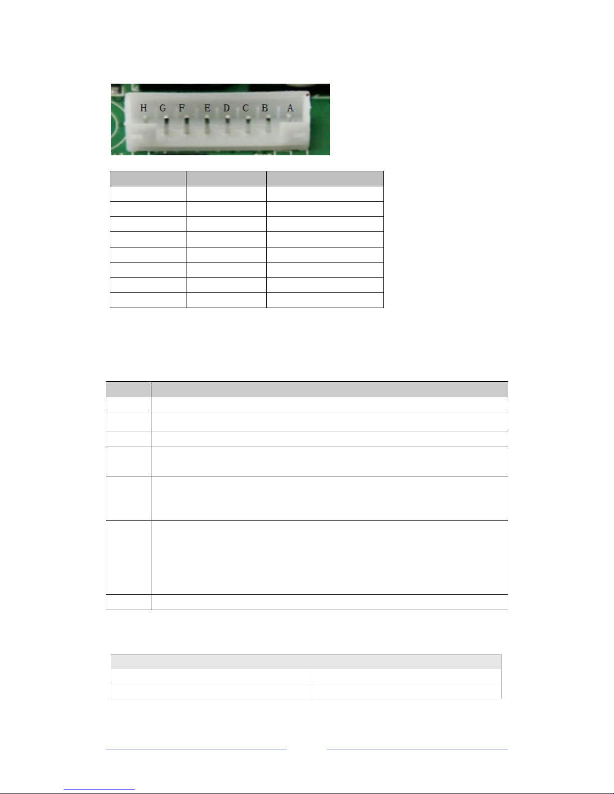
NO. port function
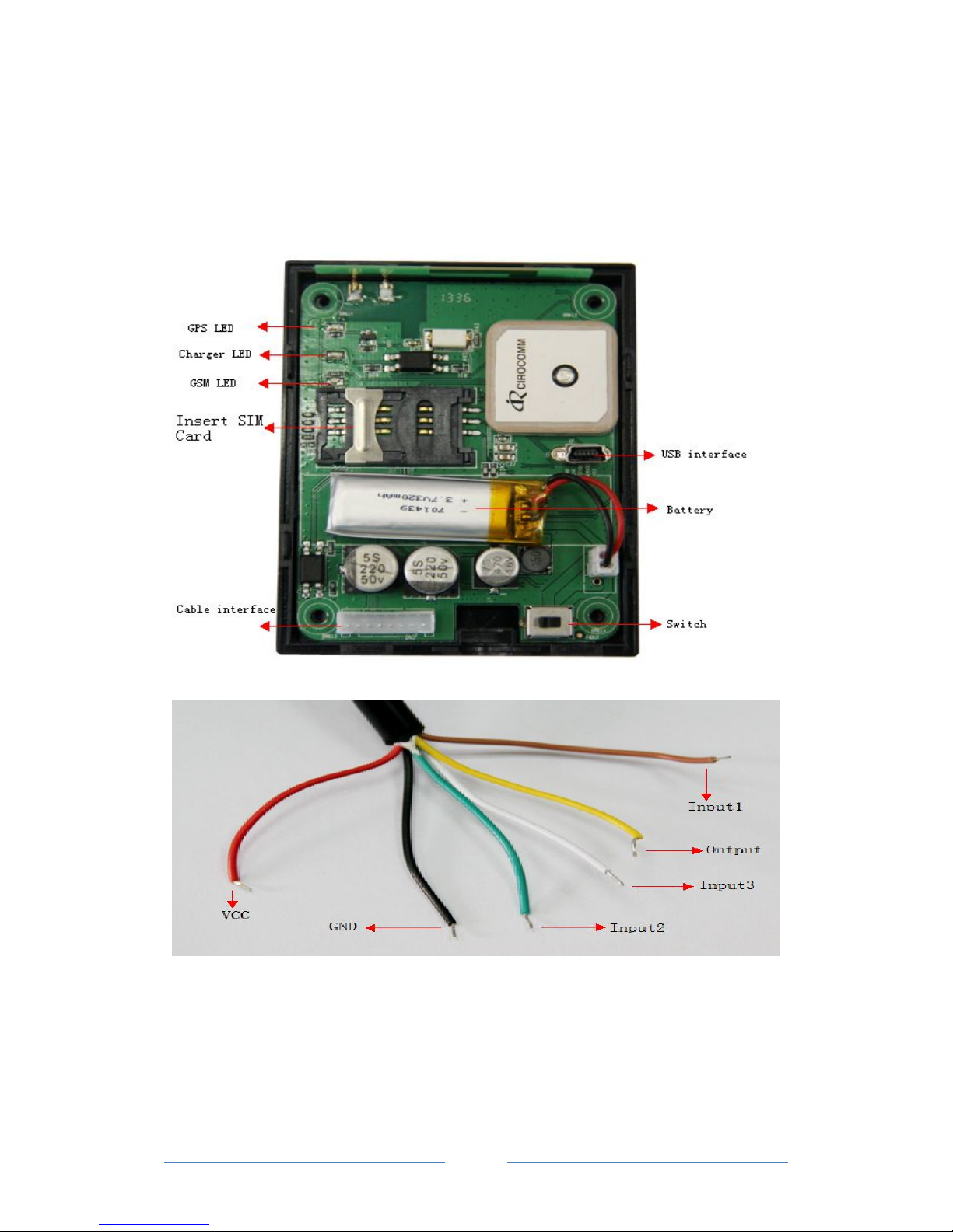
A I/O 1 VCC
B I/O 2 GND
C I/O 3 GND
D I/O 4 Digital Input 3
E I/O 5 Digital Output
F I/O 6 RESERVE
G I/O7 Digital Input 1
H I/O8 Digital Input 2
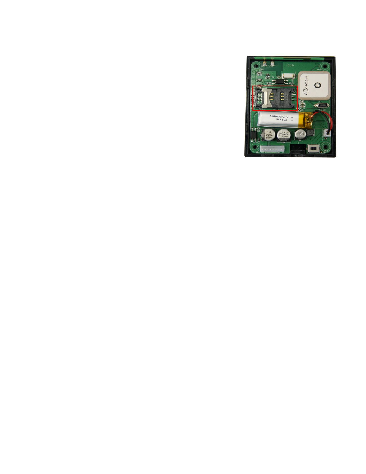
Notes: The sequence of the 8 sockets in the diagram are for the corresponding
sockets in the above picture. Please do not confuse the direction, the Switch is the
right side of I/O Sockets. The function is as below:
NO. Function
I/O 01 The anode of power input socket
I/O 02 GND, use for input GND
I/O 03 GND, use for input GND
I/O 04 When this cable is connected to GND(port 02), Device will send a GPRS
alarm data to Server. Alarm type is “01”
I/O 05 Using a phone can set the voltage value of the digital output through
“025” instruction, high or low, by virtue of it, user can remote Control
the Car window or door close/open
I/O 07 When this cable is connected to high, Device will send a GPRS alarm
data to Server. And when connect is lose , Device also will send a GPRS
alarm data to server, alarm type is “50”, “51”, through it , user can
monitor the status of ignition or Car window status
*At present, most of customers use this cable to connect to the engine of car.
I/O 08 The function is similar as I/O 07,alarm type is “52”, “53”
LED Status
Blue LED - indicating GPS status
Flashing (on for 0.1 second and off for 1seconds) AVL201 has a GPS fix
Off AVL201 has no GPS fix