TZUMI WOLF WARRIORS User manual

Be sure to read this manual before riding
Add:Tingshan Industrial Zone, Yanjiang Town, Linhai, Zhejiang, China
Tel:0576-84170056 Fax:0576-84170022 E-mail:[email protected]
Web:www.tzumi.com

Introduction
Thank you for purchasing UMI’s electric four wheeler, and we sincerely welcome you to join users of UMI’s
electric four wheeler.
To ensure a safer and more enjoyable driving experience, you should thoroughly familiarize yourself
with the various items described in this manual before driving. Your personal safety protection depends
not only on your own aler tness and familiarity with the operating techniques, but also on your familiarity
with the mechanical per formance of electric four-wheeler s. Ever y time you check before driving, regular
maintenance is the most basic condition. When you need regular maintenance or repair, please contact
our company’s special maintenance depar tment, knowing how to ser vice your car, and ensuring that
your car always maintains the best performance. If you have all kinds of mechanical and technical
knowledge and maintenance tools, you can provide spare parts catalogues and official spare par ts to
help you with all kinds of maintenance and repair work.
This instruction manual will explain in detail the correct operation method, simple maintenance, adjustment
method, and durable use of the UMI’s electric four-wheeled vehicle; if some technical specifications of
the vehicle are changed, some pictures or contents in this manual are different from the actual situation
of the vehicle. Please understand. The company reser ves the right of final interpretation; I wish you a
happy driving, thank you again for purchasing the UMI’s electric vehicle.
The driver and occupant
This type of electric four-wheeler is designed for use by one driver and one occupant (not allowed to carr y children
under the age of 12). It is forbidden to exceed the load quality of the vehicle specified in this manual.
Road Conditions
This type of electric four-wheeler is designed for driving on flat roads only.
If the technical specifications are changed, some pictures or contents in this manual may differ from the actual
situation of the vehicle. Please understand it. The company reser ves the right of final interpretation.
Note: Please pay attention to the part with “◆”
Failure to follow the instructions on the instructions may result in personal injur y or damage to the equipment.
This instruction manual should be treated as a permanent part of the electric four-wheeler, even when the vehicle
is transferred to another person, it should be transferred to the new owner along with the vehicle.
Important considerations
01 02

Water is strictly prohibited from entering the components of UMI’s electric four-wheeled vehicle appliances,
especially the controller. When cleaning the vehicle, users must pay attention to slow acceleration when
the vehicle star ts.
When the battery indicator reaches the lowest two grids (or the voltmeter indicator is in the yellow value),
charge it! Otherwise, it will cause great damage to the batter y.
The car charging plug cannot be touched by hand, other wise the voltage will cause harm to the human
body.
03 04
III. Operation Guideline
Pre-drive inspection............................ ...15.
Brake pedal and accelerator pedal .......15
Steering system (handler)................ ...16....
Driving operation ........................ ..........17..
Brake operation ......................... ........17......
Parking operation ....................... ..........18..
IV. Maintenance and repair
Maintenance ............................ .............19...
I.Safe driving of electric four-wheelers
Safe driving guidelines.............................05
Loading........................ ................ .....05...... .
Ⅱ.Safe driving of electric four-wheelers
Tail light fixture location map... ..............06..
Instrument and indicator .... ..............07......
Adjustable seat .................... ........07............
Cigarette lighter, radio, ignition switch.......08
Headlight control switch .........................09
Turning signal switch .................... .......09.....
Front light switch ....................... .......09.......
Wiper switch ............................... ...09...........
Gear knob switch ......................... ......10.......
Parking lock ...................................... ...10.....
Power off switch ................................... ...11.
Remote control .........................................11
Remote control ................................... ...11...
Contents
Charger .............................. .......11................
Car door lock ............................ .........12......
Window lift and inner door handle........12
Charging precautions ................. ..........12..
Steering system (disc)................ .....13.........
Horn switch ............................. .....13............
Air conditioning .......................................14
Simple troubleshooting................... ......21..
Suspension and steering system ... ......22.
Electronic control system ................... ..23.
Battery maintenance....................... . ....24. ..
V. Vehicle storage 25........................................
VI. Vehicle identification ........... ...26...
VII. Main technical parameters..........27
VIII. Electrical schematic ............ ...28..
IX. Tips on after-sales services ..........29
WARNINGS

1、 ◆Electric four-wheelers are only suitable for people who have a driver's license or who are qualified after
training! If you are manipulating an electric four-wheeled vehicle for the first time, please have a trained
technician to monitor it to avoid accidents.
※Please do not drive at night when the lights are dazzling, the line of sight is dead, and you are not war y.
2、 ◆It is strictly forbidden to drive vehicles with fatigue.
3、 ◆It is strictly forbidden to drive the vehicle with the outside mirror folded.
4、 ◆It is strictly forbidden to use a mobile phone or mobile phone while driving.
5、 ◆Adjust the seat to the position for proper driving before driving.
6、 ◆Be especially careful driving at road intersections, entrances and exits of car parks and lanes.
7、 ◆Speeding is prone to accidents, so you should follow the speed regulations and never drive more than the
specified speed.
8、 ◆Avoid driving through rough roads, because malfunction may damage to the body structure due to uneven
road sur face.
9、 ◆Before driving an electric four-wheeled vehicle, be sure to check the driving before driving.
10、◆Do not be too close to other motor vehicles during driving. It is strictly forbidden to rush and rush, and
strictly abide by local traffic regulations.
Loading: ◆ Only 150kg (two people) load capacity is allowed, and if overloaded, it will affect
the stability and handling of the vehicle.
Ⅰ.Safe Driving of Electronic Four Wheelers
Tail light fixture location map
05 06
High brake light
License Plate Light
Rear tail light
Charger socket interface
Turn signal
Reversing light
GUIDELINE FOR SAFE DRIVING
II. Vehicle Part Map and Instructions for Use

(1) Left and right turn indicators: When the turn signal button is toggled, the left
and right turn indicators will flash.
(2) High beam indicator: When the dimmer switch is turned to the “ ” position,
the high beam indicator will light.
(3) Charging meter: Displays the battery level when the electric door lock is turned
on.
(4) LCD pointer meter: The pointer points to the current speed when the vehicle is
driving.
(5) Speed digital display: The number shows the current speed when the vehicle is
driving.
(6) Odometer: Record the mileage of the vehicle.
(7) Reverse indicator: The reverse indicator lights when the switch button is in the
“R” position.
(8) Position position light: The neutral indicator lights when the switch button is in
the “N” position.
(9) Forward indicator: When the switch button is in the “D” position, the forward
indicator will light and the display is currently in D1 or D2.
(10)Parking indicator: When the vehicle is in the “P” parking condition, the parking
indicator will light up.
07 08
Adjustable seat (Figure 3)
Pull the front and rear adjustment levers to adjust the front and rear position of
the seat.
The seat back angle can be adjusted by pulling up the backrest angle adjustment
lever.
Figure 2
Figure 3
12V power supply (Figure 4)-1
Provide a 12V/120W power supply.
Radio (Figure 4)-2
It is used to listen to AM/PM broadcasts, and you can also play MP3s by inserting a TF card into the b port or a USB flash
drive in the c port.
a. Power button b. TF card slot c.USB port d. Play/Pause button
e. Previous song f. Next song g.AM/FM/MP3 switch h. Volume - i. Volume +
Ignition switch (Figure 4)-3
(1)Turn ON the switch and turn it to this position to turn on the power.At this point, the car key cannot be pulled out
(2)When the OFF switch is turned to this position, the power will be turned off and the car key can be pulled out.
Figure 4
1.12V power supply 2.Radio 3.1. Ignition Switch
Front and rear
seat adjustment
Backrest angle
adjustment
1 12
3 4 5 6 7 8 9 10
Meters and indicators (Figure 2)

09 10
Headlight control switch (Figure 5)
Figure 5-1 shows the headlight control switch
OFF: In this position, the headlights, position lights, tail lights, and
instrument lights are turned off.
In this position, the position light, tail light, and instrument light are on.:
In this position, the headlights, position lights, tail lights, and
instrument lights are on.
:
Push down to the high beam and push up to the dimming light.:
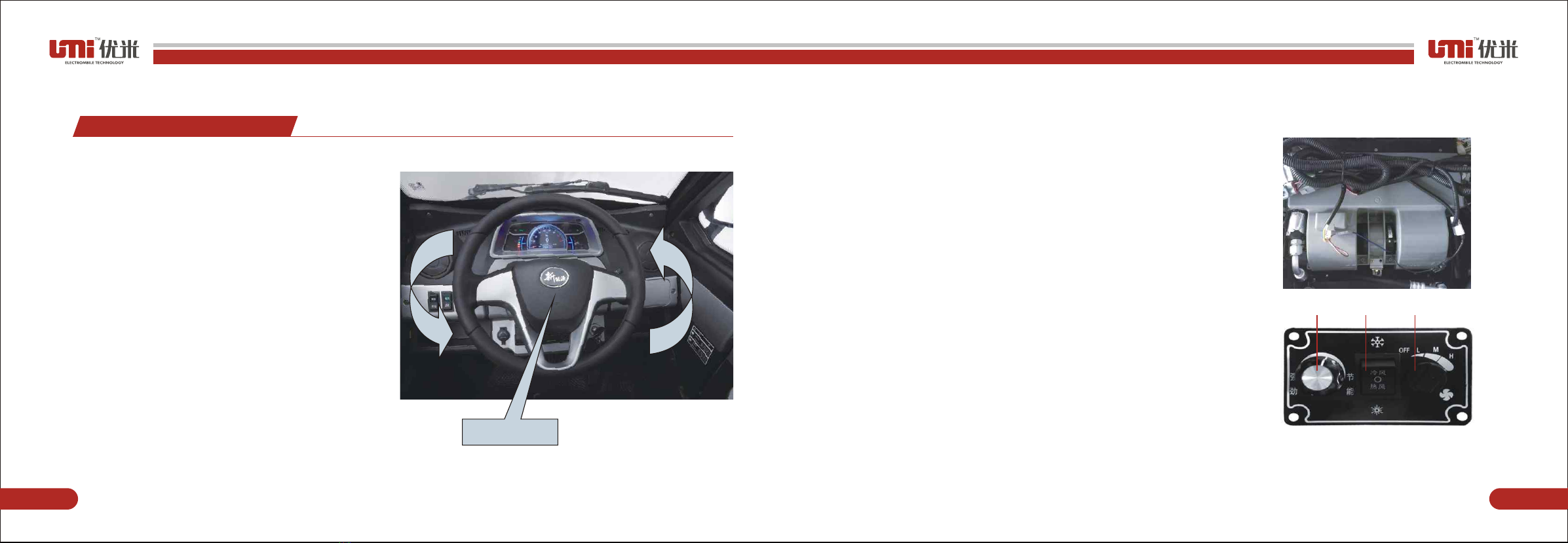
Gear knob switch (Figure 7)
The gear knob switch has 3 gear positions, and the gear knob is used
to select the gear position.
R file: It is shown in Figure 1. When the adjustment knob is in the “R”
position, the vehicle travels backwards and the reversing image
automatically opens.
N file: It is shown in Figure 2. When the adjustment knob is in the “N”
position, the power system stops working. Note: Parking must be used
in conjunction with parking.
D file: As shown in Figure 3, when the vehicle is in the “D” for ward gear,
the vehicle travels forward.
Figure 4 shows the watering cover. Gently press down on the water-
filled cover to open it. Twist the kettle lid to add the glass wash solution.
After the addition, the kettle lid can be locked and the water-filled cover
can be closed.
Figure5
Figure6
1
Figure7
Figure8
2 3 4
①②
③
① ②
1
2
Figure 5-2 shows the turning signal switch
Turning the right turn signal when pushing the “↑” position upwards means turning
to the right, and the right turn indicator lights up.
Turning the left turn signal when pushing the “↓” position down means turning to
the left, and the left turn indicator lights up.
In the “●” position, the signal light goes out.
Wiper control switch (Figure 6)
Figure 6-1 shows the front windshield water spray switch
Push the switch up to spray the front windshield
Figure 6-2 shows the wiper switch
It is divided into 3 files, and the front and rear push switch selects the gear position
from OFF to stop (stop), LOW (slow speed), HIGH (fast).
Do not operate the windshield wiper while the windshield is dry, as it may damage the wiper blades.
Parking lock (Figure 8)
Lock the car: Pull up the parking lever, and the rear wheel locks the car
and cannot move.
Unlocking: When the parking lock is in the locked state, press and hold
the front end button of the handbrake lever, lift the lever slightly, and
push the lever down to the bottom.

11 12
Power off switch (Figure 9)
When the power-off switch is in the 1 state, the power is turned on and
the car can be operated.
When the power-off switch is in the 2 state, the power is off and the car
cannot be operated.(It is also a hidden anti-theft measure)
Door lock (Figure 13)
Unlock the vehicle first. Click the remote control unlock button or use
the key to insert a to unlock the door lock, then pull the handle b to
open the door.
b
a
1
2
Figure13
Figure14
Figure12
充电口翻盖
Figure10
Figure11
1
2
Remote control (Figure 10)
When the button 1 is pressed, the vehicle lock is turned on, and when the
button 2 is pressed, the vehicle is locked.
Charging interface (Figure 11)
1.When the meter displays low battery, the user needs to charge, open
the charging port, and plug the external power into the charging port to
charge.
2.The charging interface is for charging and is not allowed to be powered on.
3.Do not touch the positive and negative terminals with metal or hands to
prevent the appliance from short-circuiting or burning the skin.
Charger:
1.Use a stable quality, model-matched charger to charge, the charger should
have over-charge, over-current, over-voltage and other protection functions.
2. When the battery is less than 80%, the red indicator light will be on when
charging. When charging, the battery is 100% green, and the battery is full.
Window lift and inner door handle (Figure 14)
When in the car, pull the handle 1 at the door to open the door.
The door glass on both sides of the car is adjusted by electric lift. By
pressing button 2, press button 2, the window is lowered; pull up button
2, the window rises.
Charging precautions:
1.The new car battery is not full, the user needs to charge after driving, and
the key brake should be removed when charging.
2.It is strictly forbidden to exceed 12 hours per charging time. When the
vehicle is not in use, it should be charged once a month.
3.It is strictly forbidden to use a non-national standard charger to charge the
vehicle. The charger should be placed in a well ventilated position when
charging. Do not charge in the place where debris or flammable or explosive
materials are stored.
4.It is strictly forbidden to charge indoors. When charging, store the vehicle
outdoors or in an open position. No debris or inflammable or explosive
materials are allowed around.
5.The ambient temperature during battery charging is preferably 10 to 30 ° C
and maintains good ventilation.
6.It is strictly forbidden to use the charger on other vehicles to charge the vehicle.
7.Do not charge the vehicle in wet areas with rain.

13 14
1.Centering on the direction of the pipe string, turn the steering
wheel left and right to adjust the steering function. When
steering the steering wheel with both hands, the left hand is the
main and the right hand is the auxiliary;
2.When turning the steering wheel to the right, the left hand
starts to rotate to the right and the right hand assists to rotate.
3.When turning the steering wheel to the left, the right hand
starts to rotate to the left and the left hand assists to rotate.
4.Turn the steering wheel angle according to the driving route.
When driving on a straight road, the two hands should hold the
steering wheel firmly and correct the direction at any time to
keep the vehicle in a straight line.
5.When turning the steering wheel, the force is too strong, and
the emergency is urgent. Do not turn the steering wheel after
the vehicle stops. When driving on uneven roads, hold the
steering wheel with both hands; in case the steering wheel is out
of control, an accident will occur.
Air conditioning (Figure 16)
Air conditioning function switch (Figure 17)
1.① Temperature regulation: When the air conditioner is in the cooling
state, the air conditioner temperature is controlled by the adjustment
knob ①, which represents the lowest temperature; the energy saving
represents the highest temperature. The temperature gradually
increases from left to right.
2.② Cold/hot air switching: Use the toggle button to select cooling or
heating, toggle to the cooling mode, and toggle to the heating mode.
When the switch is set to “O”, the air conditioner is turned off. When the
air conditioner is turned off, the rotar y ③ adjustment button has a
natural wind-blown in.
3.③Air volume adjustment: There are 4 speeds, which are adjusted by
turning the knob.
OFF file: no air, air conditioning stops working
L file: small air volume
M file: medium air volume
H file: large air volume
Figure15
STEERING SYSTEM (DISC TYPE)
Horn switch (Figure 15)
When you press this switch button, the speaker will beep.
Horn
Figure16
Figure17
1 2 3

15 16
Before each driving, the vehicle should be routinely inspected to ensure that the electric four-wheeler performs well to
ensure safe driving.
Turn the ignition on and watch the position indicated by the fuel gauge. The vehicle should be charged when it is near
the red mark position.
Brake pedal and accelerator pedal (Figure 18)
1.Fig. 17 (1) shows a suspension brake pedal, and the driver controls the strength of the braking force by controlling the
amount of depression.
2.Fig. 17 (2) shows the organ type accelerator pedal, and the driver controls the strength of the power by controlling the
amount of depression.
Both the brake pedal and the accelerator pedal are operated by the right foot.
1.The steering function is adjusted by centering on the direction
of the pipe string and adjusting the steering function. When the
two hands are in the direction of manipulation, the left hand is
the main and the right hand is the auxiliary;
2.When turning to the right, the left hand pushes the handle in
the forward direction, and the right hand assists the handle to
the rear to reach the right steering position;
3.When turning to the left, the right hand pushes the handle in
the forward direction, and the left hand assists the handle to the
rear to reach the left steering position;
4.According to the direction of rotation of the driving road, when
driving on a straight road surface, the two hands should hold the
handle tube in a stable direction and correct the direction at any
time to keep the vehicle in a straight line.
5.When the direction of rotation is turned, the force is not allowed to be too strong, and the sharp turn is urgent. After the vehicle
stops, do not turn the direction. When driving on uneven roads, hold the direction with both hands; in case the steering is out of
control, an accident will occur.
Figure 18
STEERING SYSTEM (HANDLE)
Figure 19
1
2
PRE-DRIVE INSPECTION
驾 驶 前 的 检 查
III. Operation Guidelines
POWER DISPLAY

15 16
Preparation before starting: Open the parking lock of the vehicle, make sure that the power-off switch is in the state
of 1 in Figure 9, insert the key into the ignition switch, and rotate it to the “ON” position.
Turn the gear knob switch to the “D” position and lower the parking lever.
Slowly accelerate the accelerator pedal, the vehicle starts, and the accelerator pedal is released when decelerating.
◆Warning:
Do not quickly perform a throttle operation. Otherwise, the electric vehicle may quickly rush out and may lose control.
The door should be locked in time and the parking lever should be pulled up. Never leave the car key in the lock hole
of the ignition switch.
Turn off the power off switch when leaving (see page 11);
A superior quality anti-theft device should be used.
◆Warning:
Tire (front wheel pressure: 200KPa rear wheel pressure: 250KPa)
The tire pressure should be checked regularly and adjusted.
The tire’s pressure can only be checked when the tire is cooled.
Always check for punctures on the tires, especially if there is a leak in the tire.
Check the tread for cuts, nails or other sharp objects. Inspect the rim for indentations, dents, or deformation.
When the tread pattern is ground to the tread wear limit mark, the new tire should be replaced.
◆Warning:
If the tire pressure is not up to standard, the tire surface will be excessively worn and may cause a car accident. If the
tire pressure is too low, the tire will slip or come out of the rim.
It is very dangerous to use tires that are very worn, which will affect the adhesion between the tire and the road,
causing difficulty in driving or even accidents.
ANTI-THEFT POINTS
DRIVING OPERATION
BRAKING OPERATION
To reduce the speed of the vehicle, first release the accelerator pedal, step on the brake pedal, and select the
appropriate braking force according to the specific situation.
◆Warning: Special care must be taken when driving on wet or soft surfaces and in rainy conditions, whether braking,
accelerating or steering.
Note: 1. When driving a steep slope, you should first release the accelerator pedal and use the front and rear wheel
brakes to reduce the speed.
2. When driving the road slips or bends, do not use the brakes to give the brakes to avoid accidents.
PARKING OPERATION
When parking, turn the gear knob switch to the “N” position, turn the ignition switch to the OFF position and pull up
the parking lever (see page 10)

IV. Maintenance and Repair
17 18
Maintenance cycle: The maintenance period based on driving mileage is the basis for the implementation of regular
maintenance and lubrication of the vehicle. If you are driving at high speed for a long time under bad conditions,
you must increase the number of maintenance; if the electric four-wheeled vehicle has been overhauled or has been
hit, you must ask the maintenance department personnel to carefully check the main parts of the electric vehicle,
repair or Replace the par ts that have been misplaced or damaged to ensure the safety of the vehicle.
Maintenance method (Figure 20)
◆ The rear axle needs to be replaced with gear oil every time the vehicle travels 2,000 km.
◆ Open the bolt 1 and run out of the gear oil, then tighten the bolt 1. Open the bolt 2 and pour the gear oil (85W/90GL-
4) to about 1 liter. Then tighten the bolt 2 after the refueling.
Note: In order to ensure the safety and reliability of electric vehicles, electric vehicles are not allowed to be modified. Replace with
new original parts or equivalent parts of the same quality for repair or maintenance. If other poor quality parts are used, the
performance and operating functions of the electric vehicle will be affected.
Warning: In order to ensure the safety of personnel, no matter the maintenance work of any program, be sure to turn off the power,
park the car on a flat and hard ground and stabilize it.
Note: If you park your car for more than one month or stop using it during the winter, you need to do maintenance work to prevent
deterioration, aging and corrosion of tires and batteries.
Unless the driver or owner of the vehicle has a full set of repair tools and maintenance information, and is a qualified mechanical
professional, the professional should be responsible for maintenance and repair.
From a safety point of view, we claim that these items should be maintained or repaired by the maintenance department personnel.
Note: 1. If the vehicle is often driven in particularly humid or dusty areas, it is best to shorten the specified maintenance period.
2.If you are driving on uneven roads frequently, please maintain them in time to ensure the performance of the vehicle.
1
2
Figure 20
MAINTENANCE

19 20
(二)Suspension and Steering System
(一)Power supply and braking
Fault
Vehicle cannot drive
Unstable speed
Drive motor
abnormal sound
Battery can’t be
charged
Reason
The key switch is placed in the “OFF” state or the gear
knob is in the neutral position
Battery is dead
Battery wiring electrode is corroded or loose
The key switch wire is loose or damaged
Accelerator switch is damaged
Power off switch is not turned on
Drive motor failure
Parking lever is not lowered
Damage to the accelerator pedal
Drive motor bearing wear
Motor damage
Damaged charger
Poor contact of the charger
Battery is damaged
Over-discharge of battery
Dealing Methods
Rotate the key to the position of “0N” to select
the direction of movement of the shift switch
Recharge
Clean the corrosion area and tighten the link nut
Connect the wires and repair the key switch
Replace the switch
Turn off the power switch
Check the faulty part for repair or replace parts
Release the parking lever
Replace the accelerator pedal
Replace bearing
Repair damaged parts or replace the motor
Check charger failure, repair or replace charger
Plug in the charger plug correctly
Replace the battery
Check or replace the battery
Fault phenomenon
Uneven tire wear
Steering is not
flexible, the direction
is swinging
(Swing, tremble or
vibrate)
Brake deviation
Not enough power
Reason
Tire pressure is too low
irectional column bearing lubricating oil
Each moving part hinge loses lubricating oil
Steering column wear
Uneven tire inflation pressure
Steering wheel steering
Steering column lock nut loose
Wheel swing
Loose hub nut
Uneven tire inflation pressure
Uneven wheel braking force
Brake shoes are severely worn
The brake oil pipe leaks oil and the brake fluid is not enough
Brake shoes and brake discs are oily or water y
Dealing Methods
Inflate to the recommended barometric pressure
Inject a proper amount of oil
Spare parts for moving parts
Replace the steering column tube
Adjust tire inflation pressure
Tighten the lock nut
Repair or replace the wheel
Tighten the nut
Adjust tire inflation pressure
Adjusting the twitching shoe
Replace brake shoes
Tighten the tubing joint after venting, add brake fluid
Clear
Simple Troubleshooting (Table 1)

21 22
(三)Electronic Control System
Battery maintenance (Figure 21)
This model uses a closed battery (without water)
Note: Do not disassemble the closed battery electrolyte cover.
When the vehicle is not used for a long time, please remove the batter y and
fully charge it and store it in a cool, ventilated and dry place.
When the battery post is corroded, remove the batter y and clean it.
(wash with boiled water)
Note: When removing the batter y, turn off the ignition switch, and then remove
the negative pole first. Install the positive pole first and then install the negative
pole. Do not misplace the positive and negative poles.
Fault phenomenon
Turn on the key switch, the
power indicator has no display,
no contactor pulls the “click”
sound
Turn on the key switch, the
power indicator has a display,
and there is a contactor to pick
up the “tick” sound electric
vehicle does not start.
The vehicle somes times stops
The vehicle stops upon start
Reason
Key switch disconnected
Loose or open circuit connector
Control circuit or power failure switch is damaged
Battery pack polarity reversed
Handbrake lever is not returned
Shift knob is damaged
Accelerator failure
Contactor contact failure
Speed controller failure
Drive motor failure
The controller is damp or drenched
Circuit over current and over temperature
protection system not activated
Loose circuit connector
low power
Drive motor failure
Dealing Methods
Repair or replacement
Fasten the connector or connect the wire
Replace
Change polarity
Adjust
Inspection, repair, replacement
Check the faulty part for repair or replacement parts
Inspection, drying
Check and eliminate whether the parking device
has been fully released for long-term transportation,
climbing or replacing the controller
Tighten the connector and connect the wires
Battery charging
Inspection, repair
Figure 22
Figure 21
Maintenance and repair of hydraulic brakes (please send to designated repair shop for
maintenance) (Figure 22)
Liquid level: If the liquid level is not oiled as shown in Figure 1, it is necessar y to add oil.
Deflation: Open the cover first, loosen the bolt as shown in Figure 2, and operate the brake handle one by one.
Repeat the deflation several times.
Tighten: After exhausting, hold the brake handle as shown in 3. Tighten the bolt cover.
1 2 3

V. Vehicle Storage VI. Vehicle Identification
23 24
In order to store electric vehicles for a long period of time, for example, in winter, several steps are required to prevent
malfunction or damage to the parts caused by long-term use of electric vehicles.
In addition, some maintenance work is required before the storage is prepared, otherwise the maintenance work is
often forgotten when the electric vehicle is used again.
Replace the rear axle gear oil.
Cover the electric vehicle with a car cover.
The vehicle nameplate is located on the lower right side of the seat, next to the parking lever. It includes
information such as frame number, model, brand, vehicle quality, motor model, maximum output power, rated
voltage, loading quality, and production date.(Figure 23)
The above frame number is required when repairing and replacing parts.
Figure 23
The frame number, factory information, etc. are printed on the side of the parking lever,
which can be found after the right door is opened.
VEHICLE PLATE
STORAGE
When the motor is taken out of the storage room and used again
Remove the car cover and wipe the electric car clean. If the storage time has exceeded 4 months, the axle gear oil
should be replaced.
Charge if necessary, then install the battery.
Carry out all Pre-drive inspections, first test the electric car at low speed for a period of time in areas where traffic is
not busy to ensure safety.

VIII. Electrical Schematic
VII. Main Technical Data
25 26
1.Dimensions (mm)
2.Electric type
4.Wheelbase (mm)
6.Rated maximum load mass (kg)
8.Maximum speed (km/h)
9.Braking method
11. Brake operation mode
13.Suspension method
15.Number of tires
17.Steering Type
19.Rated passengers
21.Motor
22.Recharge mileage
Electric four wheeler
1610mm
260kg
40km
One for four disc brakes
Pedal disc brake
Former McPherson suspension
4
Disc (or handle)
3 people (including driver)
2300X1080X1645mm
60V/1000W/1200W
≥60km
3.Minimum ground clearance (mm)
5.Rear track (mm)
7.Total mass (kg) (without battery)
9.Braking distance
10.Braking method (front wheel)
12.Braking method (rear wheel)
14.Differential ratio
16.Tire specifications
18.Battery specification model is recommended to match
20.Parking mode
130mm
1090mm
325kg
10m Dry state 5~8m, wet state 8~10m
Disc brake
Disc brake
8:1
125/65/12
6-EVF-45Ah/58Ah
Hand brake

27 28
IX. After-sales Services
No.
1
2
3
4
5
6
7
8
9
Component
Name
Frame
Direction handle
Lower board
Electric machine
Controller
Rear bridge
Gearbox
Wiper motor
Instrument
Three Guarantee
Period
Twelve
months
Twelve
months
Twelve
months
Three
months
Identification Standards Notes
1“Three guarantee” is not given to damage caused by improper handling or impact;.
2“Three guarantee” is not given to privately modifying the frame structure;.
1“Three guarantee” is not given to human impact, and collisional fracture;.
1“Three guarantee” is not given to shell cracking, coil ablation,
motor wire cutting, etc. caused by human factors
.
1“Three guarantee” is not given when the outlet is artificially cut,
the label is torn, and the date is modified.
.
2“Three guarantee” is not given to private opening or artificially
modified
.
“Three guarantee” is not given to damage caused by improper
driving or improper operation
1“Three guarantee” is not given to shell cracking due to collision, breakage,
and transportation
.
2“Three guarantee” is not given to disassembly and assembly, resulting in
gear missing
.
“Three guarantee” is not given to artificial packaging damage
1“Three guarantee” is not given to artificial packaging damage.
1.“Three Guarantee” Period and Failures
Note: (1) For unspecified three-packages, please refer to the “Three-Pack of Par ts and Components” document.
(2)The right to interpret the “Three Guarantee” term is attributed to Taizhou UMI Electric Vehicle Technology Co., Ltd.
2.“Three Guarantee” Period and Failures
10
11
12
13
14
15
16
17
converter
Heater
control box
Directional
column
Damping
Brake
system
Wheel tire
Wheel
Front axle
Six
months
Six
months
Six
months
Six
months
Six
months
one
month
Six
months
Six
months
Short circuit, open circuit, no voltage output, unstable
output voltage and affect the use;
1.The outlet end remains intact and untouched;
2 Internal short circuit, open circuit or other reasons
affect the use;
.
1 Deformation, fracture under normal use
2 Shock absorption oil seal’s serious oil leakage
.
.
Tubing oil leakage, brake stuck or broken
Surface cracking, drumming, interlayer breakage
or exposed wire
Trachoma, cracking, swinging, deformation
Desoldering, cracking, deformation at the weld
1“Three guarantee” is not given to man-made
disassembly and assembly, water damage
2.“Three guarantee” is not given when the converter
inside is opened privately;
.
1“Three guarantee” is not given when the outlet is
cut, the label, the nameplate is torn, and the date is
modified.
2.“Three guarantee” is not given when the product
is opened privately or artificially modified.
.
1“Three guarantee” is not given to human impact,
and collisional fracture;
.
1.
corroded or used, collision and overload cause
deformation.
“Three guarantee” is not given when the whole is
“Three guarantee” is not given to brake shoe or
when brake shoes can be used normally after
commissioning and maintenance.
“Three guarantee” is not given to human impact,
and collisional fracture;
“Three guarantee” is not given to human impact,
and collisional fracture;
“Three guarantee” is not given to human impact,
and collisional fracture;
Desoldering, cracking and deformation at the weld
De-weld, fracture, deformation of the frame
De-soldering, leading to deviation of the
whole vehicle
Welding fracture, deformation, de-soldering
1.Coil ablation or magnetic steel degradation,
shedding
2.Cracking of the casing and breakage of the
motor shaft
1.Outgoing end remains intact and
untouched
2.Internal short circuit, open circuit or
other function affects the quality of the
problem
Desoldering, breaking, deforming,
twisting
1.Faults caused by shell cracking, oil
leakage, and gear damage
Internal coil short circuit, open circuit
1.The function of the meter is not
displayed, the needle is not removed, the
reset is not reset, and the light is long.
Twelve
months
Twelve
months
Twelve
months
Twelve
months
Six months

Dear users,
Please be sure to fill out this card in a serious, detailed and true way. You can get the "Three Guarantee" ser vice by
stamping the official seal or signing the signature in one or three times (customer one, stub one, and one dealer).
If there is no warranty card, no bills, non-conformity, wrong number (including vehicle model, vehicle number,
certificate number, controller number, motor number, charger number, batter y number, etc.), the company will not
provide three-pack ser vice. Thank you for your cooperation!
Warranty Card
Unit
Name
User
Address
Postcode
Vehicle Type
Motor Type
Controller Type
Charger Type
Battery Type
Date of purchase
Frame coding
Motor number
Remote control number
Charger number
Tel
Maintenance Record
Name
Contact Time Tel
Complaint time Time of dealing Failure cause Disposing result Maintenance staff Customer’s
signature
29 30
Table of contents