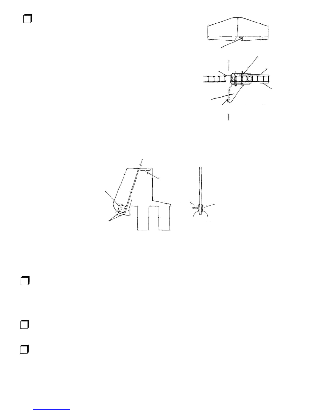
1.3Usingepoxy, glue the two 1/8" die-cut plywood
cartridge halves together. Assemble and fuelproof the PC.
Glue and clamp the reinforcing doublers on the top and
bottom of the engine mount area. Besure to line upthe
inside cavity edges of the PCwith the doublers while
clamping. Once the doublers are inplace, glue and clamp
the nose gear block asshown between the engine mount
and the tank opening on the bottom of the PC.Using a
5/32" drill bit,carefully drill a hole as shown inthe
illustration for a nose gear.
Note - the Power Cartridge is designed to be used with or
without a nose gear. Your COLT may be set up with one if
desired, and there are notes in this manual to help you use
nose gear. Whether or not you will use one with your COLT,
this is a good time to mount the nose gear block for use on
future planes.
GLUE & CLAMP
FIGURE2 - ASSEMBLY OF POWER CARTRIDGE
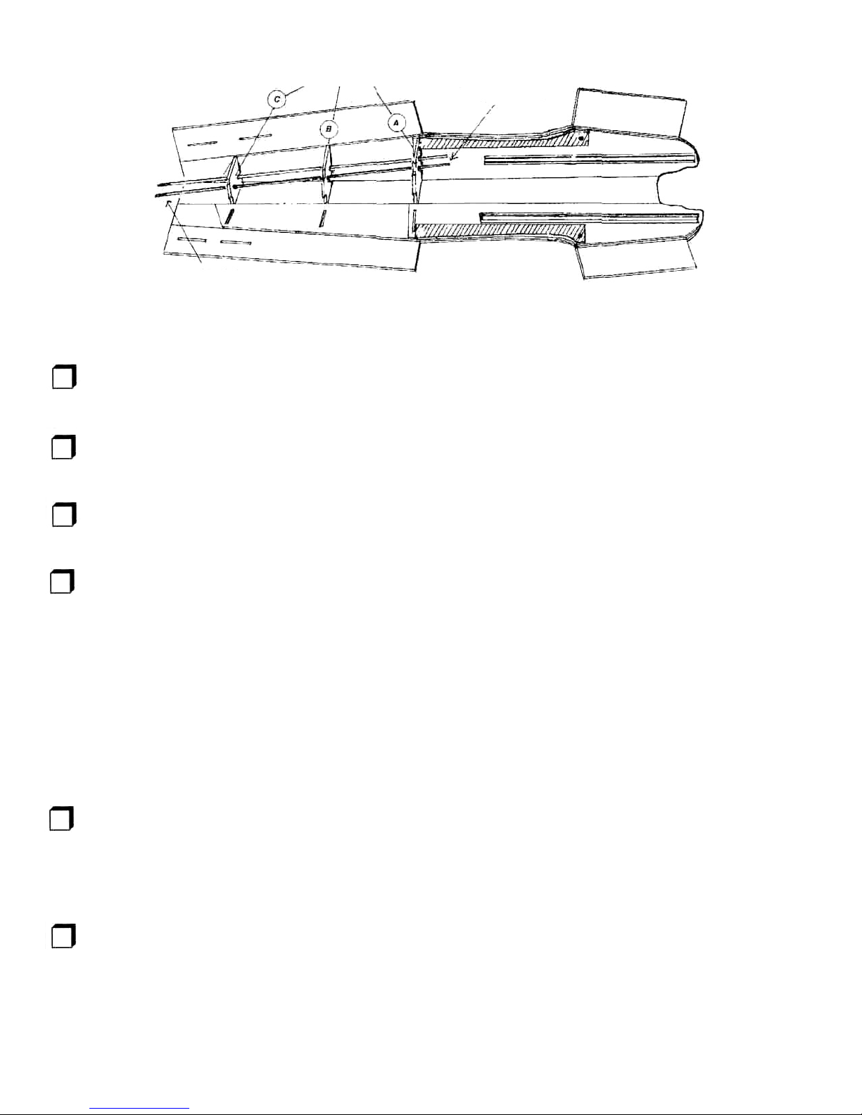
1.4Check the Power Cartridge (PC) andrailsfor a
sliding fit.Locate your 17"long PCrailsandfit them to the
sides of the PC.The PCshould beable to slide on the rails.
You want a good, sliding fit.Ifthe PCistoo snug, use sand
paper on the topandbottomofthe PCedges untilthe fit is
correct.
Aftergluinganddrilling,we liketolightlysand andpaintour
PCwith a coat of black paint before fuel proofing just for
looks.Finally,fuel proof the PCbycoating itwith thinned
epoxy (thin epoxy bymixing itas usual, then adding some
rubbing alcohol until the mixture isthin enough to "paint" on
to the PC). This isan important step. The PCmustbefuel
proofinorder to perform reliablyfor you.
DRILL5/32"HOLE
ENGINE MOUNT
TANK OPENING
FIGURE 3
MOUNTINGTHE NOSE GEAR BLOCK TOTHE PC
NOSE GEAR BLOCK
SIDEVIEW
BUILDER'S NOTE - IF YOU ARE ALREADY ACCOMPLISHED WITH A TRAINER, WE ENCOURAGE YOU TO BUILD THE "TURBO"WING FOR YOUR COLT.
YOU MAY WISH TO OWN BOTH A "TURBO WING" AND A STANDARD WING. THE TURBO WING ISA 58" WING FOR SNAPPIER AEROBATICS AND
FASTER PERFORMANCE. WE HAVE WING KITS FOR THE COLT AVAILABLE. FOR FLOATS OR GENERAL "TOOLING AROUND" USE THE
STANDARD HIGH LIFT WING. FOR HIGH-SPEED AEROBATICS, USE THE TURBO WING. IF YOU ARE BUILDING A "TURBO" VERSION, ALL
COMPONENTS OF THE WING ARE CLIPPED 3" AT THE ROOT, INCLUDING THE WING HALVES, HINGE STRIPS, AILERONS AND SPARS, PRIOR TO
ASSEMBLY. THE SPAR WILL HAVE TO BE BUILT WITH THIS IN MIND. SEE THE SECTION ON BUILDING THE TURBO WING
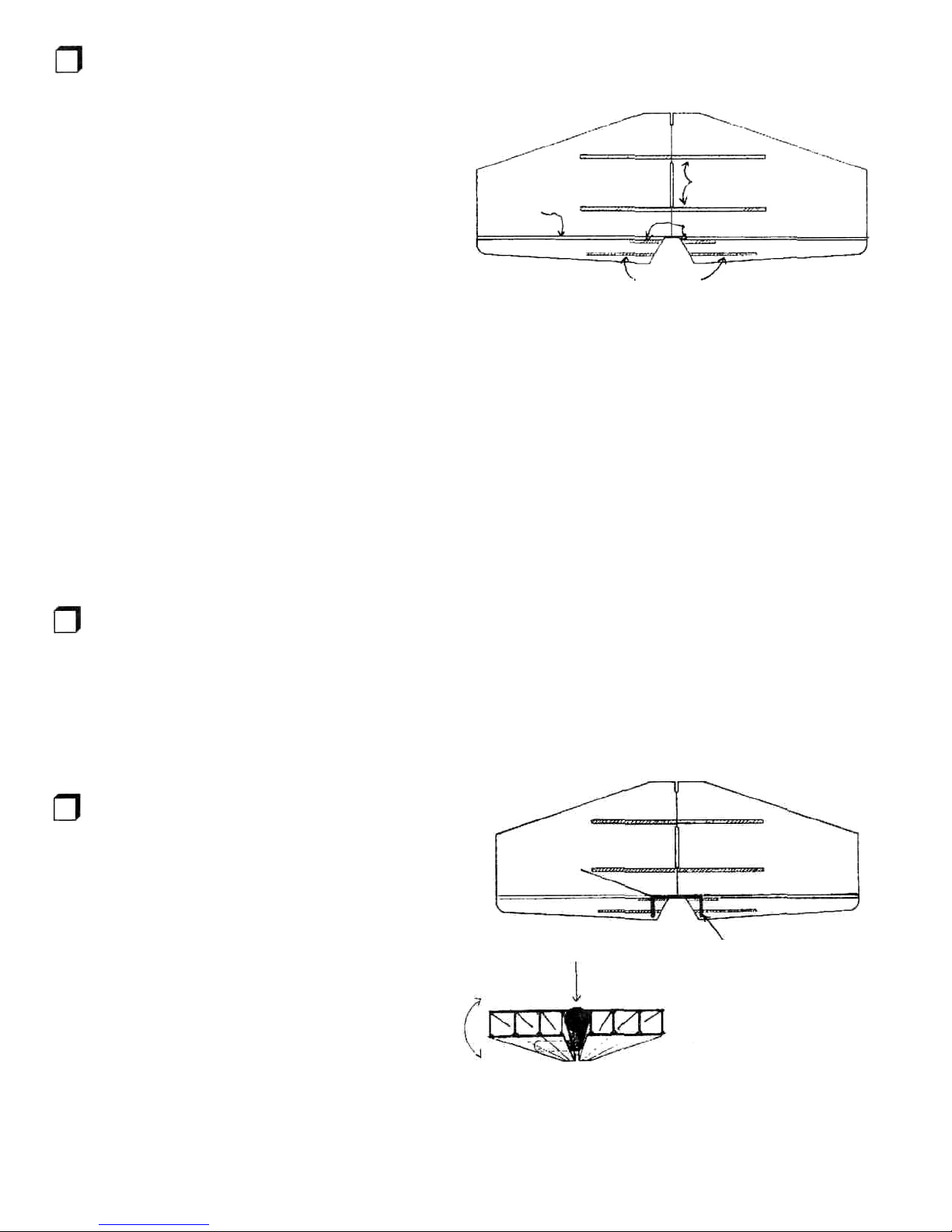
1.5Buildthe spar. Bothspar halves are identical and
angle upatthe tips. Lightly sand the spars to remove any
rough edges. Mark a centerline vertically on each dihedral
brace to identify where the spars will meet. Use slow CA
glue or 5 minute epoxy and glue the spars to one of the
dihedral braces, aligning the spars inthe center of the
brace. Clamp untildry; Now glue on the other dihedral
brace and clamp. The dihedral brace sets the "dihedral
angle" of the wing, and this angle isimportant inproviding
flight stability to your airplane. Itisimportant when
assembling the spar to observethe dihedral angle
prescribed bythe dihedral brace and to clamp while gluing
to achieve a goodbond between the spars and the braces.
TIPSOF THE SPAR ANGLE UP
USETHICKCAOREPOXYANDCLAMPUNTILDRY
DIHEDRAL BRACE
1/8"
PLY
DIHEDRAL BRACE
1/8"
PLY
TIPS OF THE
SPARANGLEUP
(DIHEDRAL IS PRESET AT 4 DEGREES)
FIGURE4 - SPAR ASSEMBLY
4