manuals.online logo
Brands
  1. Home
  2. •
  3. Brands
  4. •
  5. U.S. FAN
  6. •
  7. Fan
  8. •
  9. U.S. FAN UVQL900 User manual

U.S. FAN UVQL900 User manual

Page 1
U.S. FAN INTERNATIONAL®
P.O. Box 978
Muskogee, Oklahoma 74402 MODELS • UVQL900 • UVQL1500
!
WARNING
TO REDUCE THE RISK OF FIRE, ELECTRIC SHOCK, OR IN-
JURY TO PERSONS, OBSERVE THE FOLLOWING:
1. Use this unit only in the manner intended by the manufacturer. If
you have questions, contact the manufacturer at the address or
telephone number listed in the warranty.
2. Beforeservicingorcleaningunit,switchpoweroffatservicepanel
andlock the service disconnectingmeans to prevent powerfrom
being switched on accidentally. When the service disconnecting
means cannot be locked, securely fasten a prominent warning
device, such as a tag, to the service panel.
3. Installation work and electrical wiring must be done by a quali-
fied person(s) in accordance with all applicable codes and stan-
dards, including fire-rated construction codes and standards.
4. Sufficient air is needed for proper combustion and exhausting of
gases through the flue (chimney) of fuel burning equipment to
prevent backdrafting. Follow the heating equipment
manufacturer’s guideline and safety standards such as those
published by the National Fire Protection Association (NFPA),
andtheAmericanSociety for Heating, RefrigerationandAirCon-
ditioning Engineers (ASHRAE), and the local code authorities.
5. When cutting or drilling into wall or ceiling, do not damage elec-
trical wiring and other hidden utilities.
6. Ducted fans must always be vented to the outdoors.
7. To reduce the risk of fire, use only metal ductwork.
8. If this unit is to be installed over a tub or shower, it must be
marked as appropriate for the application and be connected to a
GFCI (Ground Fault Interrupter) - protected branch circuit.
9. Never place a switch where it can be reached from a tub or
shower.
10. This unit must be grounded.
CAUTION
1. For general ventilating use only. Do not use to exhaust hazard-
ous or explosive materials and vapors.
2. To avoid motor bearing damage and noisy and/or unbalanced
impellers, keep drywall spray, construction dust, etc. off power
unit.
3. If ventilator is installed in an unconditioned space (such as
an attic): Surroundthe ventilator with thermal insulation-tomini-
mize possible condensation.
4. Please read specification label on product for further informa-
tion and requirements.
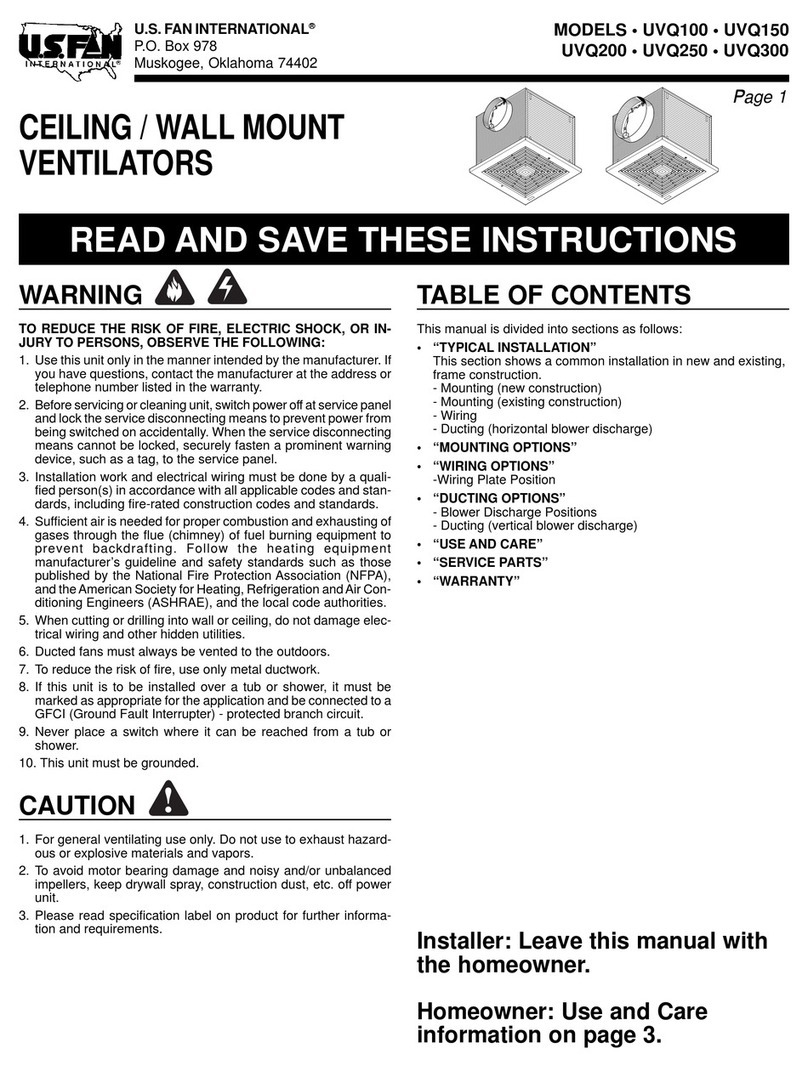
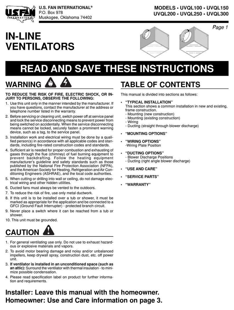
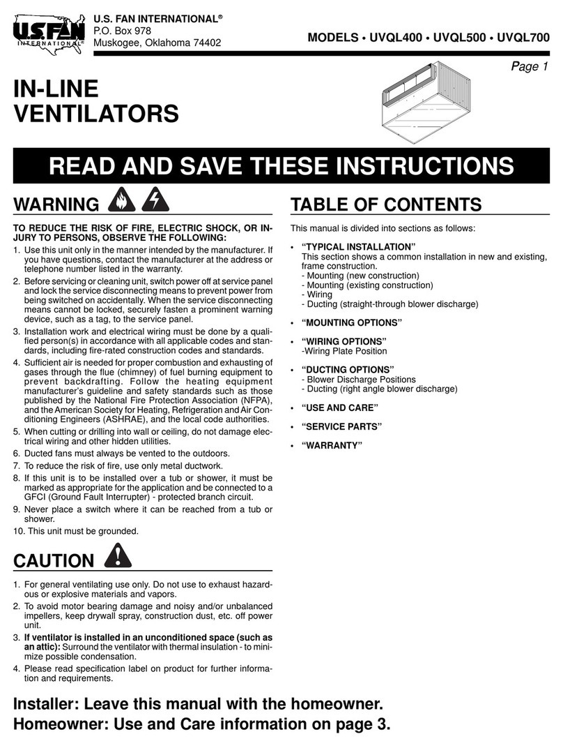
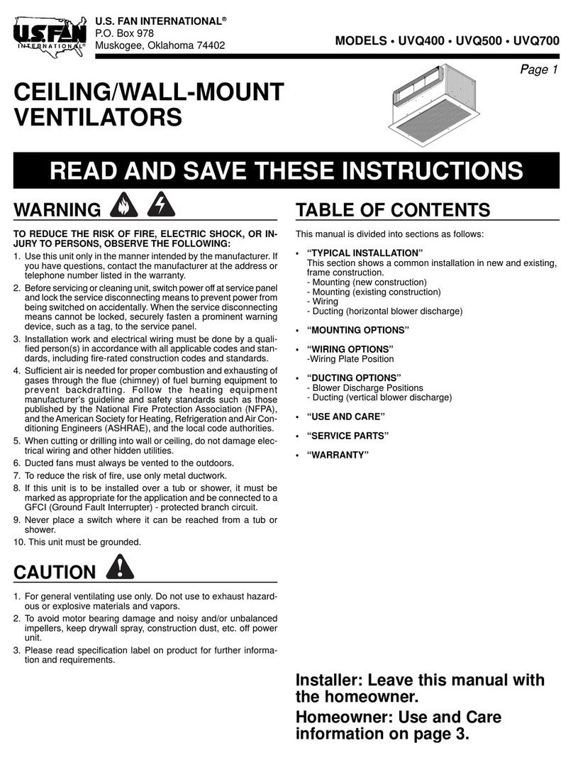
IN-LINE
VENTILATORS • 120V
READ AND SAVE THESE INSTRUCTIONS
TABLE OF CONTENTS
This manual is divided into sections as follows:
• “TYPICAL INSTALLATION”
This section shows a common installation in new and existing,
frame construction.
- Mounting (new construction)
- Mounting (existing construction)
- Wiring
- Ducting (straight-through blower discharge)
• “MOUNTING OPTIONS”
• “WIRING OPTIONS”
-Wiring Plate Position
• “DUCTING OPTIONS”
- Blower Discharge Positions
- Ducting (right-angle blower discharge)
• “USE AND CARE”
• “SERVICE PARTS”
• “WARRANTY”
Installer: Leave this manual with the homeowner.
Homeowner: Use and Care information on page 3.
Page 1
MODELS • UVQL900 • UVQL1500
Page 2
U.S. FAN INTERNATIONAL®
P.O. Box 978
Muskogee, Oklahoma 74402
TYPICAL INSTALLATION
MOUNTING
(New Frame Construction)
CEILING
JOIST
(24”
centers
shown)
12” ROUND
DUCT
(OUTLET)
ACCESS
PANEL
Factory-shipped unit installed in new construction.
MOUNTING
SCREWS
ACCESS
PANEL SCREW
Ventilator factory-
shipped
in straight-through
discharge position.
MOUNTING
BRACKETS
MOUNTING
(Existing Frame Construction)
Factory-shipped unit installed in existing construction.
TYPICAL INSTALLATION
WIRING
WIRING
PLATE
WHITE
TO
WHITE
BLACK
TO
BLACK EDGE
OF HOUSING
120 VAC LINE IN
GROUND TO
WIRING PLATE
ACCESS
PANEL
SCREW DUCTING
(Straight-through blower discharge)
Two ways to connect ductwork to a factory-shipped unit.
Ventilator can be wired from outside of housing.
Use UL approved connectors to wire per local codes.
ROOF CAP
12” ROUND
ELBOW
12”
ROUND
DUCT
WALL
CAP
IMPORTANT:
Remove shipping tape from damper
Remove the shipping tape from the damper flap and make sure
that damper flap opens and closes freely inside the ductwork. Use
duct tape to make ductwork connections secure and air-tight.
8” X 12”
TO
12” ROUND
TRANSITIONS
8” X 12” TO 12” ROUND
TRANSITIONS
12” ROUND DUCT
(OUTLET)
FINISHED
CEILING
MATERIAL
Ventilator
factory-shipped
in straight-through
discharge position.
MOUNTING
BRACKETS
8” X 12” TO
12” ROUND
TRANSITIONS
CEILING
JOIST
(24” centers
shown)
ACCESS PANEL
12” ROUND
DUCT
(INTAKE)
12” ROUND
DUCT (INTAKE)
12”
ROUND
DUCT
GRILLE NUT
(Install into square
holes in housing)
GRILLE NUT
(Install into
square holes in
housing)
Page 3
U.S. FAN INTERNATIONAL®
P.O. Box 978
Muskogee, Oklahoma 74402 MODELS • UVQL900 • UVQL1500
,,,,,,,,,yyyyyyyyy
18"
1½"
to
2½"
,,,
,,,
@@@
@@@


ÀÀÀ
ÀÀÀ
,,,
,,,
@@@
@@@


ÀÀÀ
ÀÀÀ
,,,
,,,
@@@
@@@


ÀÀÀ
ÀÀÀ
,,,
,,,
@@@
@@@


ÀÀÀ
ÀÀÀ
,,,
,,,
@@@
@@@


ÀÀÀ
ÀÀÀ
,,,
,,,
@@@
@@@


ÀÀÀ
ÀÀÀ
,,,
,,,
yyy
yyy
,,@@ÀÀ
,,@@ÀÀ
,,@@ÀÀ
,,@@ÀÀ
,,@@ÀÀ
,,@@ÀÀ
,,yy
,,,yyy
,,,yyy
22"
,y
,,,yyy
22"
1
1
/
8
"
MAX.
MOUNTING OPTIONS
WIRING OPTIONS
DUCTING OPTIONS
Mounting brackets in
factory-shipped position -
mounted directly to joists.
(Outlet parallel to joists.)
(New construction)
¼-20 hex nuts secure mounting brackets to housing. Loosen and
re-tighten or remove and replace nuts as necessary for desired
mounting bracket position.
Mounting brackets flipped
over and mounted to
additional framing.
(Outlet perpendicular to joists.)
(New or Existing construction)
BLOWER DISCHARGE POSITIONS
WIRING PLATE
POSITION
Wiring plate mounts to side or top of housing.
HORIZONTAL POWER
CABLE CONNECTION
VERTICAL
POWER
CABLE
CONNECTION
Ventilator shown in
straight-through discharge
position. (Factory shipped)
DUCT
CONNECTOR
(intake)
Ventilator shown in right-
angle discharge position.
(Change movable panel to
new location as shown.)
MOVABLE
PANEL
DUCTING
(Vertical blower discharge)
Typical ductwork connection to a ventilator converted to
right-angle discharge.
ROOF CAP
12” ROUND
DUCT
WARNING: To reduce the risk of electric shock,
disconnect from power supply before servicing.
To clean blower assembly: Removeaccess panel, unplug blower
from housing, remove blower mounting nuts, and carefully remove
blowerfrom housing. Useappropriate vacuum attachmentor a soft
cloth and mild soap or detergent to clean blower discharge area
and wheel. DO NOT ALLOW WATER TO ENTER MOTOR. Make
sure blower assembly is completely dry before reinstalling.
Motor is permanently lubricated. Do not oil or disassemble motor.
USE AND CARE
Ventilator is designed for continuous operation. If desired, it may
be controlled using an on/off switch or a solid-state, variable speed
control. Follow wiring instructions packed with control, and adhere
to all local and state codes, and the National Electrical Code.
Factory-Shipped
Straight-Through
Discharge
Factory-Shipped
Straight-Through
Discharge
Housing
Converted to
Right-Angle
Discharge
Mounting brackets flipped
over and mounted to
additional framing.
(Outlet vertical.)
(New or Existing construction)
Mounting brackets flipped
over and mounted to top of
housing. Housing secured
with cables.
(Outlet parallel to joists.)
(New or Existing construction)
Factory-Shipped
Straight-Through
Discharge
MOVABLE
PANEL
(Change to this
location)
8” X 12” TO
12” ROUND TRANSITIONS
DUCT
CONNECTOR
(outlet)
DUCT
CONNECTOR
(intake)
DUCT
CONNECTOR
(outlet)
Housing
rotated &
movable panel
covers previous
open side.
12” ROUND
DUCT
MODELS • UVQL900 • UVQL1500
Page 4
U.S. FAN INTERNATIONAL®
P.O. Box 978
Muskogee, Oklahoma 74402
SERVICE PARTS SERVICE PARTS
WARRANTY
KEY NO. PART NO. DESCRIPTION
1 97014853 Damper Flap
2 99150415 Screw, #8B x ¼* (16 req.)
3 98009520 Duct Connector (2 req.)
4 97014784 Housing Assembly
5 97014728 Mounting Bracket (2 req.)
6 99150591 Mounting Screw (4 req.)
7 97006142 Wiring Harness
8 99150471 Ground Screw, #10-32 x ½* (2 req.)
9 98005512 Wiring Adapter Plate
10 99420470 Access Panel Nut (4 req.)
11 98009531 Movable Housing Panel
12 93150487 Screw, #10-24 x .375* (8 req.)
13 98005513 Outlet Box Cover
14 99400035 Strain Relief Bushing
15 97014788 Motor Bracket
16 99260477 Whiz Nut, ¼-20* (11 req.)
17 99200202 Screw, ¼-20 x ½* (5 req.)
18 97014785 Blower Scroll
19 99080490 Motor (UVQL900)
99080491 Motor (UVQL1500)
20 93260447 Nut, Hex Flange 5/16-18* (5 req.)
21 98009516 Support Bracket
22 99680019 Wheel Clamp
23 99020274 Blower Wheel (Includes Key No. 22)
24 98009514 Inlet Ring
25 99150417 Screw, #8-18 x ¼* (5 req.)
26 98009513 Scroll Support Channel
+ 97014848 Blower Assembly Complete (UVQL900)
(Includes Key Nos. 15 thru 26)
+ 97014849 Blower Assembly Complete (UVQL1500)
(Includes Key Nos. 15 thru 26)
27 98009532 Access Cover
28 99150472 Access Cover Screw (4 req.)
Order replacement parts by PART NO. - not by KEY NO.
* Standard hardware - may be purchased locally.
+ Not shown assembled.
LIMITED WARRANTY
WARRANTY AND DISCLAIMER: U.S. Fan International extends this limited warranty to the original buyer and warrants that products manufactured by the Company shall be free from original defects in workmanship and materials for two years
from date of shipment, provided same have been properly stored, installed, serviced, maintained and operated. This warranty shall not apply to products which have been altered or repaired without the Company’s express authorization, or altered
or repaired in any way so as, in the Company’s judgment, to affect its performance or reliability, nor which have been improperly installed or subjected to misuse, negligence, or accident, or incorrectly used in combination with other substances. The
Buyer assumes all risks and liability for results of use of the products. Warranties on purchased parts, such as but not limited to bearings, sheaves, belts, couplings, electric motors, pumps and controls are limited to the terms of warranty extended
by our supplier.Polyethylene tubing and cooling pads are warranted to be free of defects in material and workmanship for a period of 90 days from date of shipment and a like warranty applies to the cross fluted cellular type cooling cells for a period
of two years from date of shipment provided same have been properly handled, stored, installed, serviced, maintained and operated.And further, not subjected to excessive heat, corrosive agents or chemicals, or mechanical abuse that may cause
tearing, crushing or undue deterioration nor used on a system or in a manner other than that for which it was designed as explained in the product literature.
LIMITATION OF REMEDY AND DAMAGES:All claims under this warranty must be made in writing and delivered to P. O. Box 978, Muskogee, Oklahoma, 74402, within 15 days after discovery of the defect and prior to the expiration of two years
from the date of shipment by the Company of the product claimed defective, and Buyer shall be barred from any remedy if Buyer fails to make such claim within such period. Within 30 days after receipt of a timely claim, the Company shall have
the option either to inspect the product while in Buyer’s possession or to request Buyer to return the product to the Company at Buyer’s expense for inspection by the Company. The Company shall replace, or at its option repair, free of charge, any
product it determines to be defective, and it shall ship the repaired or replacement product to Buyer F.O.B. point of shipment; provided, however, if circumstances are such as in the Company’s judgment to prohibit repair or replacement to remedy
the warranted defects, the Buyer’s sole and exclusive remedy shall be a refund to the Buyer of any part of the invoice price, paid to the Company, for the defective product or part.The Company is not responsible for the cost of removal of the defective
product or part, damages due to removal, or any expenses incurred in shipping the product or part to or from the Company’s plant, or the installation of the repaired or replaced product or part.Implied warranties, when applicable, shall commence
upon the same date as the express warranty provided above, and shall, except for warranties of title, extend only for the duration of the express warranty. Some states do not allow limitations on how long an implied warranty lasts, so the above
limitation may not apply to you.The only remedy provided to you under an applicable implied warranty and the express warrantyshall be the remedy provided under the express warranty, subject to the terms and conditions contained therein. The
Company shall not be liable for incidental and consequential losses and damages under the express warranty, any applicable implied warranty, or claims for negligence, except to the extent that this limitation is found to be unenforceable under
applicable state law. Some states do not allow the exclusion or limitation of incidental or consequential damages, so the above limitation or exclusion may not apply to you. This warranty gives you specific legal rights, and you may also have other
rights which vary from state to state.No employee, agent, dealer, or other person is authorized to give any warranties on behalf of the Company or to assume for the Company any other liability in connection with any of its products except in writing
and signed by an officer of the Company.
REPLACEMENT PARTS If replacement parts are ordered, buyer warrants that the original components in which these replacement parts will be placed are in satisfactory working condition, and when said replacement parts are installed, the
resultant installation will operate in a safe manner, at speeds and temperatures for which the original equipment was purchased.
TECHNICAL ADVICE AND RECOMMENDATIONS, DISCLAIMER: Notwithstanding any past practice or dealings or any custom of the trade, sales shall not include the furnishing of technical advice or assistance or system design. Any such
assistance shall be at the Company’s sole option and may be subject to additional charge.The Company assumes no obligation or liability on account of any recommendations, opinions or advice as to the choice, installation or use of products. Any
such recommendations, opinions or advice are given and shall be accepted at your own risk and shall not constitute any warranty or guarantee of such products or their performance.
GENERAL In no event shall any claim for consequential damages be made by either party. The Company will comply with all applicable Federal, State, and local laws.
WARNING
U.S. Fan International products are designed and manufactured to provide reliable performance but they are not guaranteed to be 100% free of defects. Even reliable products will experience occasional failures and this possibility should be
recognized by the User. If these products are used in a life support ventilation system where failure could result in loss or injury, the User should provide adequate back-up ventilation, supplementary natural ventilation or failure alarm system, or
acknowledge willingness to accept the risk of such loss or injury. WARNING DO NOT use in HAZARDOUS ENVIRONMENTS where fan’s electrical system could provide ignition to combustible or flammable materials unless unit is specifically built
for hazardous environments. CAUTION Guards must be installed when fan is within reach of personnel or within seven (7) feet (2.134 m) of working level or when deemed advisable for safety. DISCLAIMER The Company has made a diligent effort
to illustrate and describe the products in this literature accurately; however, such illustrations and descriptions are for the sole purpose of identification, and do not express or imply a warranty that the products are merchantable, or fit for a particular
purpose, or that the products will necessarily conform to the illustrations or descriptions or dimension.
12
3
5
6
7
28
9
12
10
14
15 16
17
18
21
16
4
22
13
19
23
20
24
17
26
27
28
3
11
16
25
2
BLOWER
ASSEMBLY
613127 April 2000 99042770D

This manual suits for next models

1

Other U.S. FAN Fan manuals

U.S. FAN UVQ900 User manual

U.S. FAN

U.S. FAN UVQ900 User manual

U.S. FAN UVQ80 User manual

U.S. FAN

U.S. FAN UVQ80 User manual

U.S. FAN UVQ100 User manual

U.S. FAN

U.S. FAN UVQ100 User manual

U.S. FAN UVQ400 User manual

U.S. FAN

U.S. FAN UVQ400 User manual

U.S. FAN UVQL100 User manual

U.S. FAN

U.S. FAN UVQL100 User manual

U.S. FAN UVQL400 User manual

U.S. FAN

U.S. FAN UVQL400 User manual

Popular Fan manuals by other brands

Panasonic Whisper Value-Lite FV-08VSL2 installation instructions

Panasonic

Panasonic Whisper Value-Lite FV-08VSL2 installation instructions

Fantech RE(C) 54 installation manual

Fantech

Fantech RE(C) 54 installation manual

BVN BRF I Series User manual & certificate of warranty

BVN

BVN BRF I Series User manual & certificate of warranty

kincrome KP1013 manual

kincrome

kincrome KP1013 manual

NuTone 769RF installation instructions

NuTone

NuTone 769RF installation instructions

Hunter Torrence Owner's guide and installation manual

Hunter

Hunter Torrence Owner's guide and installation manual

UNITED USF-694 instruction manual

UNITED

UNITED USF-694 instruction manual

Vent-Axia Kinetic Advance White installation instructions

Vent-Axia

Vent-Axia Kinetic Advance White installation instructions

Fanaway LD-48 FAN IN installation instructions

Fanaway

Fanaway LD-48 FAN IN installation instructions

Eci Telecom Ribbon SBC 7000 Assembly

Eci Telecom

Eci Telecom Ribbon SBC 7000 Assembly

LUCCI AIRFUSION CLIMATE II LD52WH user manual

LUCCI

LUCCI AIRFUSION CLIMATE II LD52WH user manual

Alpha Fan ALLY-5B/56 instruction manual

Alpha Fan

Alpha Fan ALLY-5B/56 instruction manual

Vallox 125E MV manual

Vallox

Vallox 125E MV manual

Taurus ALPATEC BOREAL 12 LEGEND instruction manual

Taurus

Taurus ALPATEC BOREAL 12 LEGEND instruction manual

Emerson CF245LBS00 manual

Emerson

Emerson CF245LBS00 manual

Vortice LINEO 250 ES Instruction booklet

Vortice

Vortice LINEO 250 ES Instruction booklet

Allied Healthcare MCV200 manual

Allied Healthcare

Allied Healthcare MCV200 manual

NSB FAN KELLY User manual & installation guide

NSB FAN

NSB FAN KELLY User manual & installation guide

manuals.online logo
manuals.online logoBrands
  • About & Mission
  • Contact us
  • Privacy Policy
  • Terms and Conditions

Copyright 2025 Manuals.Online. All Rights Reserved.