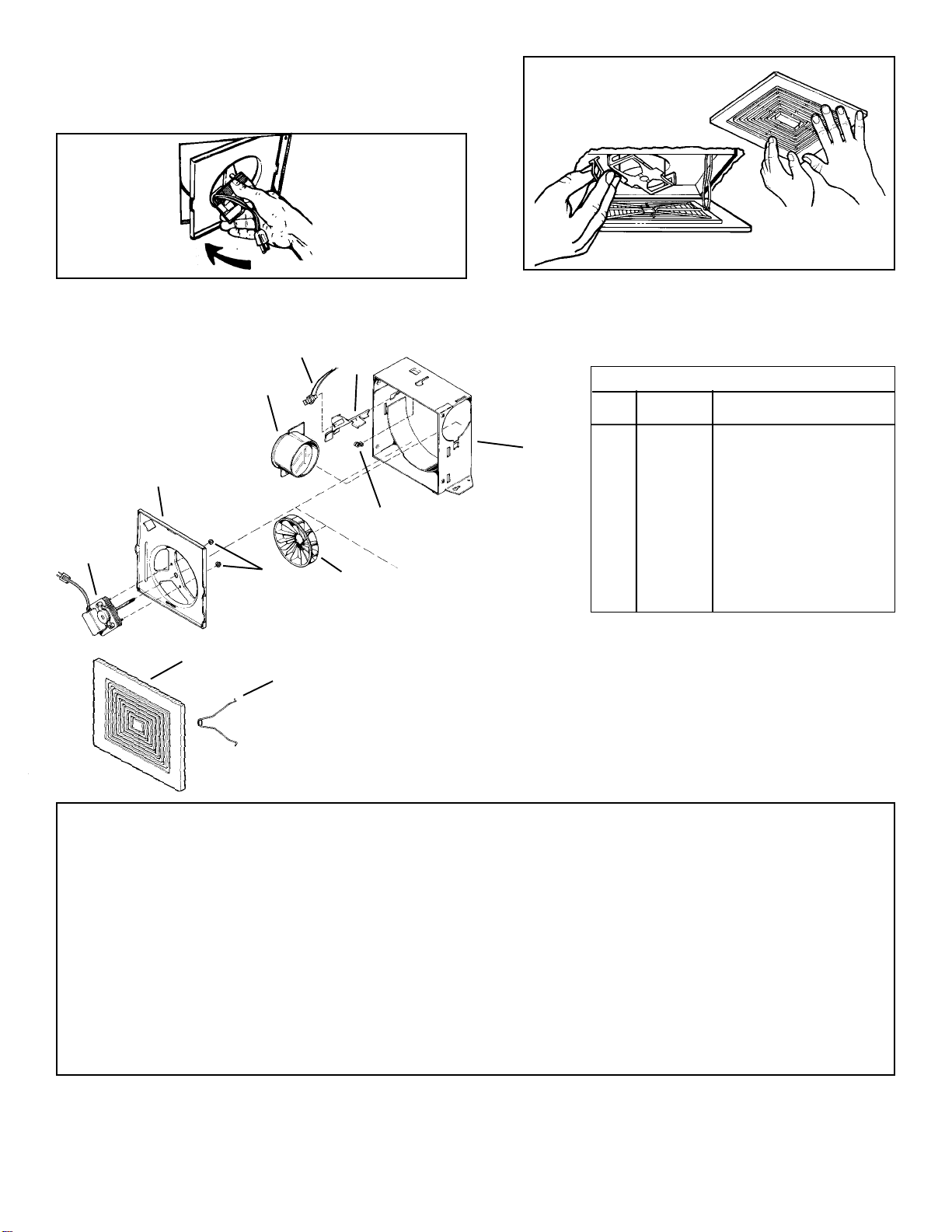
KEY
NO. PART NO. DESCRIPTION
1 97011723 GrilleAssembly (Includes Key
Nos. 1 & 2)
2 99140187 Grille Springs (2 Required)
3 99080254 Motor
4 98006791 Motor Plate
5 99110655 Blower Wheel
6 99260428 Nut #6-32 (2 Required)
7 97008632 Damper/Duct Connector
8 99270748 Receptacle
9 98006773 Wiring Cover
10 99390015 Ground Clip
11 97008319 Housing Assembly
Order replacement parts by part number - not key
number.
12
6
35
11
9
8
7
4
6.Install 3" roundductontodamper/ductconnector. If rigidductwork
is used, its seam should be positioned at top of damper/duct
connector. Tape the joint and extend ducting to a wall cap or roof
cap.Makesurethedamperoperatesfreely.Ceilingorwallcannow
be finished.
7.Replace the motor plate removedinStep1.Insert two motor plate
tabs into slots in housing and then pivot motor plate up until third
tab on plate snaps into matching slot in housing. Make sure tabs
hold motor plate securely in place. Plug in motor. (Fig. 5)
8.Squeeze grillesprings together and insert springs into slots
in motor plate. Push grille up against ceiling or wall. (Fig. 6)
PARTS LIST FOR UVQ50
Fig. 6
Fig. 5
10
LIMITED WARRANTY
WARRANTYAND DISCLAIMER:U.S. Fan International extends this limited warranty to the original buyer and warrants that products manufactured by the Company shall be free from original defects in workmanship and
materials for two years from date of shipment, provided same have been properly stored, installed, serviced, maintained and operated. This warranty shall not apply to products which have been altered or repaired without
theCompany’s express authorization, or altered or repaired in anyway so as, in the Company’s judgment, to affectitsperformance or reliability,norwhich have been improperly installed or subjected to misuse, negligence,
or accident, or incorrectly used in combination with other substances. The Buyer assumes all risks and liability for results of use of the products. Warranties on purchased parts, such as but not limited to bearings, sheaves,
belts, couplings, electric motors, pumps and controls are limited to the terms of warranty extended by our supplier.Polyethylene tubing and cooling pads are warranted to be free of defects in material and workmanship for
aperiod of 90 days fromdate of shipment and alike warranty applies to thecross fluted cellular type coolingcells for a period of two years from date of shipment provided same have been properly handled, stored, installed,
serviced, maintained and operated.And further, not subjected to excessive heat, corrosive agents or chemicals, or mechanical abuse that may cause tearing, crushing or undue deterioration nor used on a system or in a
manner other than that for which it was designed as explained in the product literature.
LIMITATION OF REMEDY AND DAMAGES:All claims under this warranty must be made in writing and delivered to P. O. Box 978, Muskogee, Oklahoma, 74402, within 15 days after discovery of the defect and prior to the
expirationof two yearsfrom the dateof shipment bythe Company ofthe product claimeddefective, and Buyershall be barredfromany remedy if Buyer fails to make such claim within such period. Within 30 days after receipt
of a timely claim, the Company shall have the option either to inspect the product while in Buyer’s possession or to request Buyer to return the product to the Company at Buyer’s expense for inspection by the Company.
The Company shall replace, or at its option repair, free of charge, any product it determines to be defective, and it shall ship the repaired or replacement product to Buyer F.O.B. point of shipment; provided, however, if
circumstancesare such as in theCompany’s judgment to prohibit repairor replacement to remedy thewarranted defects, the Buyer’s sole and exclusive remedyshall be a refund tothe Buyer of any partof the invoice price,
paid to the Company, for the defective product or part.The Company is not responsible for the cost of removal of the defective product or part, damages due to removal, or any expenses incurred in shipping the product or
partto or fromthe Company’s plant, or the installation of the repaired or replacedproduct or part.Impliedwarranties, when applicable, shall commenceupon the same date as the express warranty provided above, andshall,
except for warranties of title, extend only for the duration of the express warranty. Some states do not allow limitations on how long an implied warranty lasts, so the above limitation may not apply to you. The only remedy
provided to you under an applicable implied warranty and the express warranty shall be the remedy provided under the express warranty, subject to the terms and conditions contained therein. The Company shall not be
liable for incidental and consequential losses and damages under the express warranty, any applicable implied warranty, or claims for negligence, except to the extent that this limitation is found to be unenforceable under
applicable state law. Some states do not allow the exclusion or limitation of incidental or consequential damages, so the abovelimitation or exclusion may not apply to you. This warranty gives you specific legal rights, and
you may also have other rights which vary from state to state.No employee, agent, dealer, or other person is authorized to give any warranties on behalf of the Company or to assume for the Company any other liability in
connection with any of its products except in writing and signed by an officer of the Company.
REPLACEMENT PARTS If replacement parts are ordered, buyer warrants that the original components in which these replacement parts will be placed are in satisfactory working condition, and when said replacement
parts are installed, the resultant installation will operate in a safe manner, at speeds and temperatures for which the original equipment was purchased.
TECHNICALADVICEAND RECOMMENDATIONS, DISCLAIMER:Notwithstanding anypast practice ordealings or anycustom of thetrade, sales shall not include the furnishing of technical advice orassistance or system
design. Any such assistance shall be at the Company’s sole option and may be subject to additional charge.The Company assumes no obligation or liability on account of any recommendations, opinions or advice as to the
choice, installation or use of products. Any such recommendations, opinions or advice are given and shall be accepted at your own risk and shall not constitute any warranty or guarantee of such products or their
performance.
GENERAL In no event shall any claim for consequential damages be made by either party. The Company will comply with all applicable Federal, State, and local laws.
WARNING
U.S. Fan International products are designed and manufactured to provide reliable performance but they are not guaranteed to be 100% free of defects. Even reliable products will experience occasional failures and this
possibility should be recognized by the User. If these products are used in a life support ventilation system where failure could result in loss or injury, the User should provide adequate back-up ventilation, supplementary
naturalventilation or failurealarm system, or acknowledge willingness to accept the risk of suchloss or injury. WARNING DONOTuseinHAZARDOUS ENVIRONMENTS wherefan’s electrical system could provide ignition
tocombustible or flammable materials unlessunit is specifically built forhazardous environments. CAUTION Guards mustbe installed when fan is within reach of personnel or within seven (7)feet (2.134 m) of working level
or when deemed advisable for safety. DISCLAIMER The Company has made a diligent effort to illustrate and describe the products in this literature accurately; however, such illustrations and descriptions are for the sole
purposeof identification, and do not express or implya warranty that the products are merchantable, orfit for a particular purpose, or that the products will necessarilyconform to the illustrations ordescriptions or dimension.
U.S. FAN INTERNATIONAL P.O. Box 978, Muskogee, OK 74402 (800) 54USFAN — (800) 548-7326
Member Air Movement and Control Association (AMCA) 613129 April 2000 99042815B


