Ubiquiti SolarBeam SB-700-1 User manual

Off-Grid 716Wh Battery
Models: SB-700-1, SB-700-2,
SB-700-3

Introduction
Thank you for purchasing the Ubiquiti Networks® SolarBeam™. This
Quick Start Guide is designed to guide you through installation
and also includes warrantyterms.
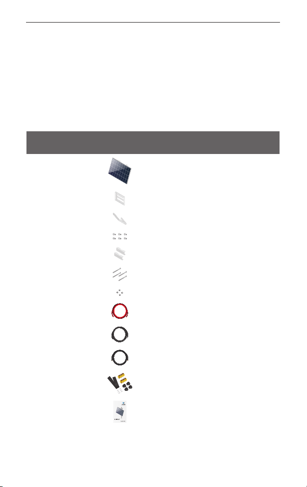
Package Contents
The SolarBeam is available in three models: SB-700-1 (single
panel), SB-700-2 (two panels), SB-700-3 (three panels).
Component SB-700-1
Quantity
SB-700-2
Quantity
SB-700-3
Quantity
Panel 1 2 3
Mounting Bracket 123
Strut 123
Bracket Screws 6 12 18
Pole Clamps 246
Carriage Bolts 4 8 12
Flange Nuts 4 8 12
DC Cable 111
NTC Thermistor 111
PV Cable N/A 1 1
Splice Kit N/A 1 1
Quick Start Guide
Off-Grid716WhBattery
Models:SB-700-1,SB-700-2,
SB-700-3
111
TERMS OF USE: Ubiquiti radio devices must be professionally installed. Shielded Ethernet cable and
earth grounding must be used as conditions of product warranty. TOUGHCable™is designed for
outdoor installations. It is the customer’s responsibility to follow local country regulations, including
operation within legal frequency channels, output power, and Dynamic Frequency Selection (DFS)
requirements.
1
Introduction
Hardware Overview
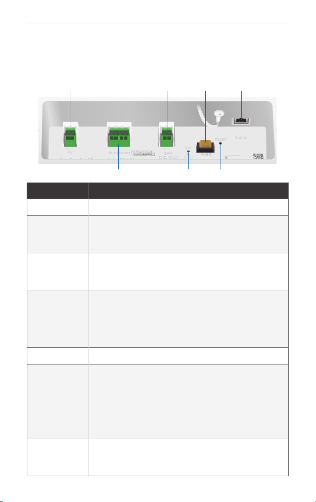
Electronics Compartment
The compartment is located on the back of the main solar panel.
DataPV 24VDC Out
SW/Gel
Fuse
SLA|Tbatt Reset
Components Description
PV Connects to PV cabling.
SLA|Tbatt
Optional: You can connect a lead-acid battery.
The maximum charge voltage is 28.2V
(default: AGM/flooded) or 27.2V (gel).
24VDC Out
Optional: You can connect a 24VDC device (40W
maximum). Enable 24VDC output through the
Configuration Interface.
SW/Gel
You have two options:
• SW Use the Configuration Interface to switch
between battery types: AGM/flooded or gel.
• Gel Select if you use a gel-type battery.
Fuse Overcurrent protection for 24VDC. Rated at 5A.
Reset Button
There are two functions:
• Restart Press and hold for threeseconds
while the SolarBeam is powered on.
• Reset to Factory Defaults Press and hold for
more than eight seconds while the SolarBeam
is poweredon.
Data
RJ45 port supports 10/100 Ethernet and passive
24V PoE output (40W maximum). Enable PoE
output through the Configuration Interface.
2
SolarBeam Quick Start Guide
Note: You can connect your load(s) to either the 24VDC
Out or Data port, or both ports, as long as the total power
consumption is less than or equal to 40W.
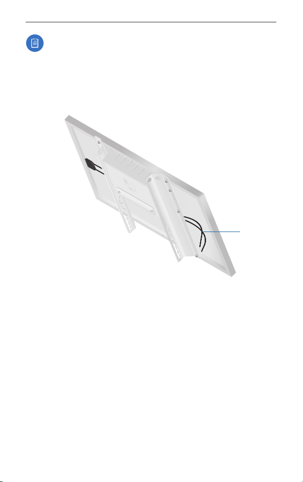
PV Cabling
Every solar panel has two Attached PV Cables, positive (+) and
negative (-).
Attached
PV Cables
Installation Requirements
• Ratchet wrench with 13 and 17 mm sockets
• 13 mm combination wrench
• 3mm wrench (Splice Kit for SB-700-2 or SB-700-3 only)
• Shielded Category 5 (or above) cabling should be used for all
wired Ethernet connections and should be grounded through
the AC ground of the PoE.
We recommend that you protect your networks from
harmful outdoor environments and destructive ESD events
with industrial-grade, shielded Ethernet cable from Ubiquiti
Networks. For more details, visit www.ubnt.com/toughcable
3
Installation Requirements

Installation Guidelines
Orient the panel towards the south (or towards the north if in the
southern hemisphere. If you prefer to set the angle just once, we
recommend to use the adjustment angle for your latitude inwinter.
Angle of Adjustment Latitude (Winter) Latitude (Summer)
10° <13° <30°
20° 13-20° 30-40°
30° 20-27° 40-50°
40° 27-34° 50-60°
50° 34-41° 60-70°
60° 41-47° 70-80°
70° >47° >80°
Note: These are approximate values to optimize energy
generation in the given season. Local weather patterns,
shading, or other environmental factors may require
different adjustments.
To use the 60° or 70° angle of adjustment, first configure the main
solar panel as follows:
1. Remove the four screws securing the electronics compartment.
2. Lower the compartment to the bottom set of mounting holes,
and secure it using the four screws.
4
SolarBeam Quick Start Guide
Installation Overview
Installation includes the following:
• Hardware Installation Mount the solar panel(s).
• Connecting the SolarBeam Connect the cables.
• Accessing the Configuration Interface Configure settings.
Hardware Installation
If you have SB-700-2 or SB-700-3, install the main solar panel first
before installing the other panels.
You have two options, pole or wall mounting. Proceed to the
instructions for your installation method.
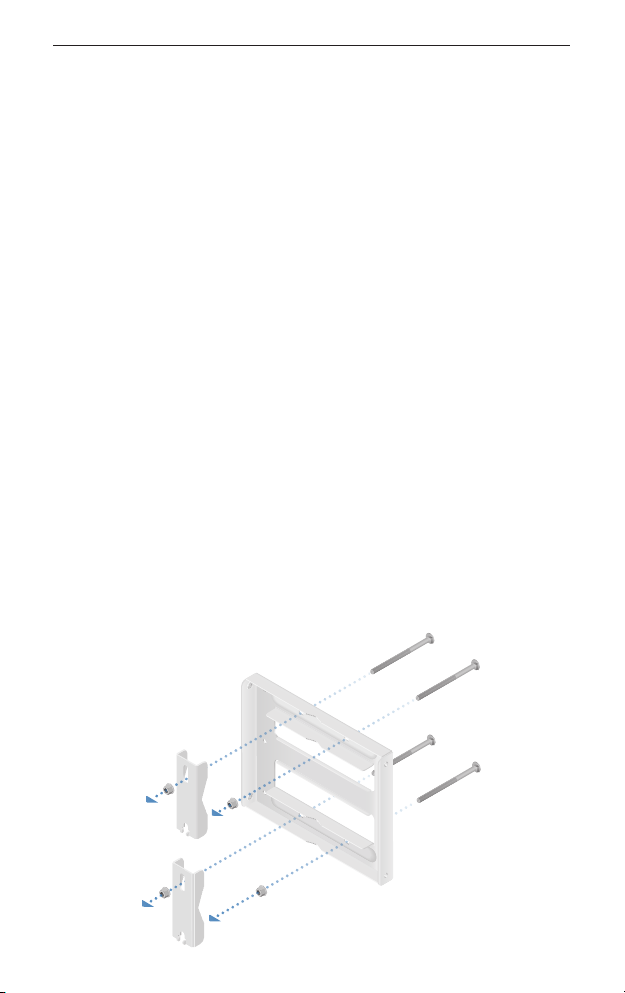
Pole Mounting
1. Attach the Pole Clamps to the Mounting Bracket.
a. Hold the Mounting Bracket with its clamps facing you and
the Angle Indicators towards the bottom.
b. Insert the two Carriage Bolts through the holes of the
Mounting Bracket.
c. Slide the hole of the Pole Clamp over one bolt of the
Mounting Bracket.
d. Place one Flange Nut on each bolt.
5
Installation Overview
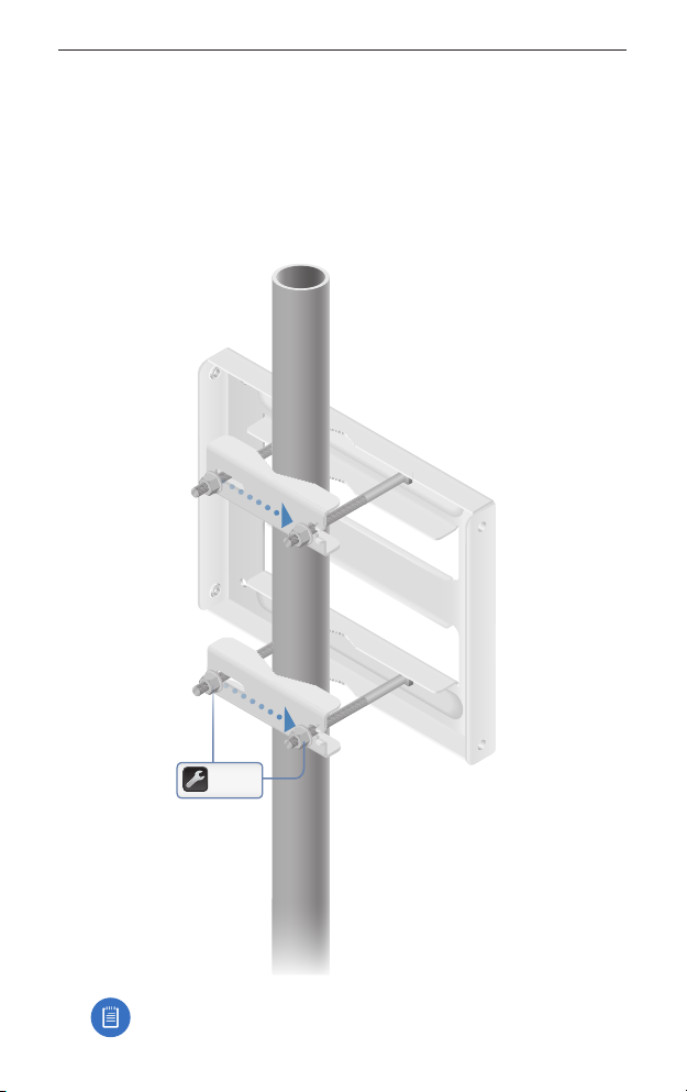
2. Mount the Mounting Bracket on the pole and secure it.
a. Place the Mounting Bracket against the pole.
b. Slide the slot of each Pole Clamp over the adjacent
CarriageBolt.
c. Tighten the Flange Nuts of the bolts to 25 N∙ m to secure the
Mounting Bracket to the pole.
25 N ∙ m
Note: The mounting assembly can accommodate a
Ø 38.1 - 101.6 mm (1.5" - 4.0") pole.
6
SolarBeam Quick Start Guide

3. Attach the Strut to the Mounting Bracket using two Bracket
Screws. Hand-tighten only.
4. Insert the Panel into the Mounting Bracket and Strut.
7
Hardware Installation
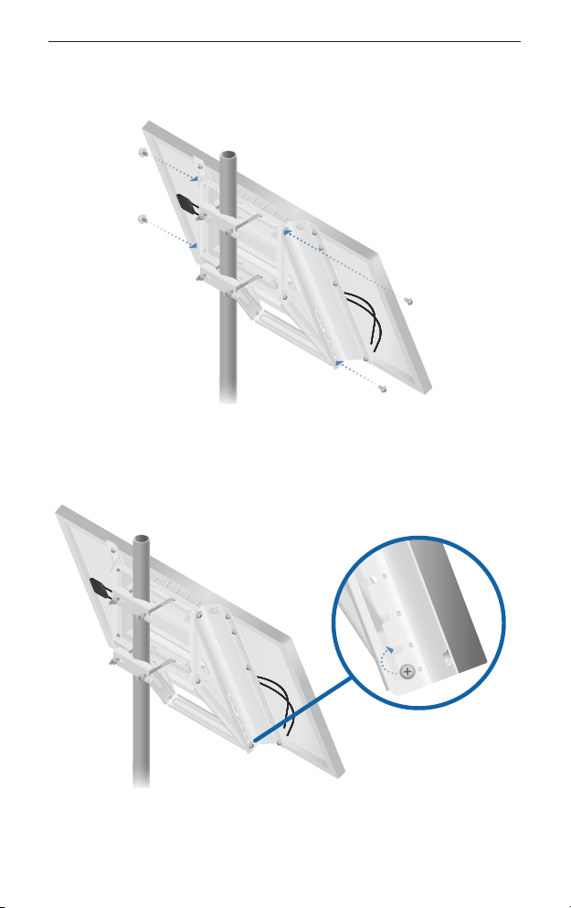
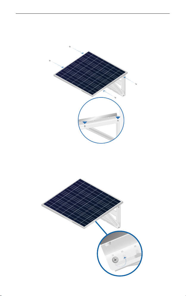
5. Attach the Panel to the Mounting Bracket and Strut using four
Bracket Screws. Hand-tighten only.
6. Adjust the angle of the Panel based on your latitude (refer to
the Installation Guidelines section on page 4). Then tighten the
six Bracket Screws to 1.7N ∙ m.
8
SolarBeam Quick Start Guide
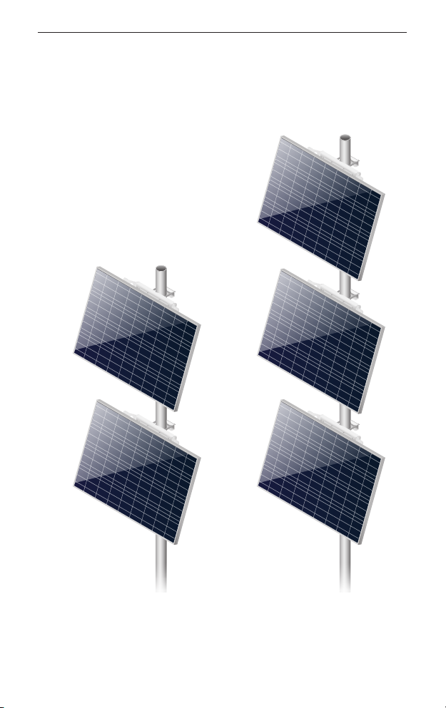
Instructions for SB-700-2 or SB-700-3
Follow the pole mounting instructions for your additional panels.
For the SB-700-3, ensure that your main solar panel is installed in
the middle position.
SB-700-2 SB-700-3
9
Hardware Installation
Wall Mounting
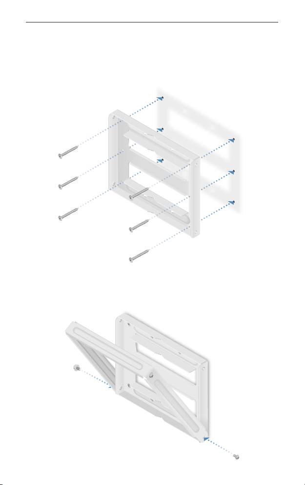
1. Position and securely fasten the flat side of the Mounting
Bracket to the wall using six M8 or 5/16" screws (not included).
2. Attach the Strut to the Mounting Bracket using two Bracket
Screws. Hand-tighten only.
10
SolarBeam Quick Start Guide
3. Insert the Panel into the Mounting Bracket and Strut. Then
attach the Panel to the Mounting Bracket and Strut using four
Bracket Screws. Hand-tighten only.
4. Adjust the angle of the Panel based on your latitude (refer to
the Installation Guidelines section on page 4). Then tighten the
six Bracket Screws to 1.7N ∙ m.
11
Hardware Installation

Instructions for SB-700-2 or SB-700-3
Follow the wall mounting instructions for your additional panels.
For the SB-700-3, ensure that your main solar panel is installed in
the middle position.
SB-700-2
SB-700-3
12
SolarBeam Quick Start Guide
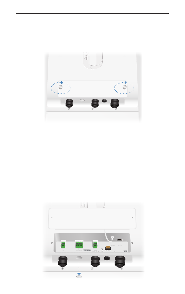
Connecting the SolarBeam
Before you begin, unscrew the thumbscrews to remove the
portcover.
When you have finished your connections, hand-tighten the
grommets and replace the portcover.
Connecting to a Battery (Optional)
You can use flexible conduit or an optional cable gland (not
included) for your connection to an external battery.
1. Punch out the cutout on the bottom of the electronics
compartment to allow the cable feed.
13
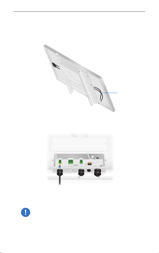
Connecting the SolarBeam

2. Feed a DC cable (not included, maximum size: 14AWG) through
the hole and wire to the SLA terminal block.
WARNING: We strongly recommend that you add
an appropriate DC breaker (interrupter) between the
SLA|Tbatt terminal block and external battery to increase
safety during installation or maintenance. Suggested
breaker rating: 30VDC/10A.
3. Wire the other end to a lead acid (AGM/flooded or gel) battery.
4. Feed the included NTC Thermistor through the hole and wire it
to the Tbatt terminal block. (You can use a cable to extend the
NTC Thermistor as needed.)
5. Attach the other end of the NTC Thermistor to your battery.
14
SolarBeam Quick Start Guide

Connecting to the DC Output (Optional)
Note: Ensure that your network device supports the
supplied voltage.
1. Remove the Fuse to disable the DC output.
2. Feed the included DC Cable through the grommet and wire it
to the 24V DC Output terminal block.
3. Wire the other end of the cable to a network device that
supports the supplied voltage.
4. Replace the Fuse to enable the DC output.
Connecting Ethernet
Note: If you enable PoE, ensure that your network device
supports PoE and the supplied voltage.
1. Feed the Ethernet cable through the grommet and connect it
to the Data port.
2. Connect the other end to your PoE network device. 15
Connecting the SolarBeam
Connecting PV Cabling
Instructions for SB-700-1
Connect the Attached PV Cables to its electronics compartment.
Attached
PV Cables
1. Feed the Attached PV Cables through the grommet.
2. Wire the positive (+) PV Cable to the positive (+) input of the PV
terminal block.
WARNING: You must wire a single PV Cable at a time
because the cables carry electricity and could short if
you connect both PV Cables at the same time.
3. Wire the negative (-) PV Cable to the negative (-)input.
4. Proceed to the Accessing the Configuration Interface section.
16
SolarBeam Quick Start Guide

Instructions for SB-700-2 or SB-700-3
You will use the included Splice Kit to connect the solar panels.
Splice Kit Components
Polyolefin Tubing Splice Blocks Grommets Plugs
1. Cut the included PV Cable to the two lengths needed for
making positive (+) and negative (-) polarity connections from
the Splice Blocks to the electronics compartment.
2. On the main solar panel, perform the following steps:
a. Feed the PV Cables through the grommet.
b. Wire the positive (+) PV Cable to the positive (+) input of the
PV terminal block.
WARNING: You must connect a single PV Cable at a time
because the cables carry electricity and could short if
you connect both PV Cables at the same time.
c. Wire the negative (-) PV Cable to the negative (-)input.
17
Connecting the SolarBeam

3. Refer to the polarity diagram for your specificmodel. Then
proceed to the Splicing the PV Cabling section.
SB-700-2 (Positive or Negative Polarity)
From Electronics Compartment Main Panel
Second Panel
SB-700-3 (Positive or Negative Polarity)
From Electronics Compartment
Second Panel Third Panel
Main Panel
Splicing the PV Cabling
These instructions show the SB-700-2; however, they apply to the
SB-700-3 as well. For specifics, refer to the polarity diagram above
for your model.
Note: Ensure that you use PV Cables of a single polarity for
each Splice Block.
1. Cut the Polyolefin Tubing to a length of 88 mm minimum.
88 mm
2. Cut the PV Cable to the length you require for your installation.
Then strip its jacket to expose 13mm of conductor wire.
13 mm
18
SolarBeam Quick Start Guide
This manual suits for next models
2
Table of contents
Other Ubiquiti Camera Accessories manuals

Popular Camera Accessories manuals by other brands


Trojan
Trojan GC2 48V quick start guide

Calumet
Calumet 7100 Series CK7114 operating instructions

Ropox
Ropox 4Single Series User manual and installation instructions

Cambo
Cambo Wide DS Digital Series Main operating instructions

Samsung
Samsung SHG-120 Specification sheet

Ryobi
Ryobi BPL-1820 Owner's operating manual