Ubiquiti UVC-G3-AF User manual


i
UniFi Video User Guide
Ubiquiti Networks, Inc.
Table of Contents
Chapter 1: Installation ..............................................1
Overview.........................................................................1
Supported Products ..............................................................1
System Requirements ............................................................1
Hardware Installation.............................................................1
Software Installation..............................................................1
UniFi Video Setup ................................................................2
Launching UniFi Video............................................................4
Non-Cloud UniFi Video Setup.....................................................4
Enabling Cloud Access from Existing Installations .................................6
Chapter 2: Cameras.................................................7
Camera Details Window ..........................................................8
Chapter 3: Map....................................................13
Defining a Map ..................................................................13
Chapter 4: Live View...............................................15
Create a New View ..............................................................15
Edit a View ......................................................................16
Chapter 5: Timeline................................................17
Selecting a Clip for Playback .....................................................17
Playback ........................................................................18
Chapter 6: Recordings .............................................21
Viewing Recordings .............................................................22
Chapter 7: Alerts ..................................................23
Alerts Home Page ...............................................................23
Chapter 8: Users...................................................25
User Details .....................................................................25
Chapter 9: Settings ................................................29
NVR Settings ....................................................................30
Appendix A: Mobile App ..........................................33
UniFi Video App for iOS..........................................................33
UniFi Video App for Android .....................................................39

ii
UniFi Video User Guide
Ubiquiti Networks, Inc.
Appendix B: Standalone Mode ....................................45
Using Standalone Mode .........................................................45
Configuring the Camera .........................................................48
Standalone Mode from UniFi Video ..............................................48
Appendix C: Contact Information ..................................51
Ubiquiti Networks Support ......................................................51
1
Chapter 1: InstallationUniFi Video User Guide
Ubiquiti Networks, Inc.
Chapter 1: Installation
Overview
UniFi Video® is a powerful and flexible, integrated IP
video management surveillance system designed to work
with Ubiquiti’s UniFi Video Camera product line. UniFi
Video has an intuitive, configurable, and feature‑packed
user interface with advanced features such as motion
detection, auto‑discovery, user‑level security, storage
management, reporting, and mobile device support.
The UniFi Video software comes pre‑installed on the UniFi
NVR and requires no additional software installation. This
chapter provides instructions for users who are not using
the UniFi NVR and wish to install the UniFi Video software
on a computer or other hardware platform that meets the
system requirements listed below.
Supported Products
The following models of the UniFi® Video Camera are
supported by v3.9:
• UniFi Video Camera G3 (UVC‑G3, UVC‑G3‑AF)
• UniFi Video Camera G3 Dome (UVC‑G3‑DOME)
• UniFi Video Camera G3 Micro (UVC‑G3‑MICRO)
• UniFi Video Camera G3 Pro (UVC‑G3‑PRO)
• UniFi Video Camera (UVC)
• UniFi Video Camera Pro (UVC‑Pro)
• UniFi Video Camera Dome (UVC‑Dome)
• UniFi Video Camera Micro (UVC‑Micro)
Note: UniFi Video 3.2.0 and above does not support
airCams.
System Requirements
• 64‑bit Debian 7.0 (or above), Ubuntu v14.04 or v16.04,
or Microsoft Windows 8/7 system with an Intel or
compatible 1.86 GHz (or above) processor with a
minimum of 2GB RAM
• Mobile: iOS or Android
• Java Runtime Environment 1.7 or newer
• Web Browser: Google Chrome
Hardware Installation
Ensure that each camera on your network is running the
latest version of the firmware. The latest firmware (and
other UniFi Video downloads) can be found online at:
www.ubnt.com/download
Follow the directions in the Quick Start Guide that
accompanied your UniFi Video Camera to install your
cameras.
Software Installation
Download the latest version of the UniFi Video software at:
www.ubnt.com/download
Then follow the instructions for your system.
Windows Installation
To install the software on Windows:
1. Run the downloaded UniFi Video installer file as
Administrator. You may be asked to allow the program
to make changes to the computer you’re installing it
on. If so, click Yes .
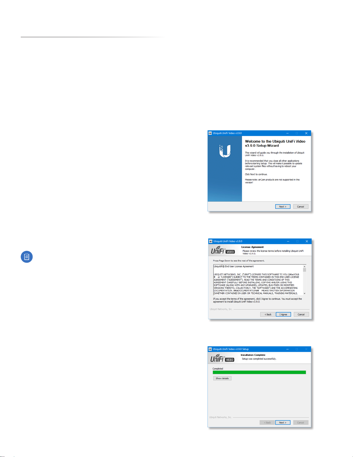
2. When the Ubiquiti UniFi Video Setup wizard starts, click
Next to continue the installation.
3. Click I Agree to accept the license agreement and
continue with setup wizard.
4. The UniFi Video Setup wizard will install files on your
system. When it is finished, click Next.

2
Chapter 1: Installation UniFi Video User Guide
Ubiquiti Networks, Inc.
5. If your computer doesn’t have Java 1.7 or 1.8 software
installed, you will be prompted to install it. Click Install
to continue.
6. Click ClosFinish the installation. This will start the UniFi
Video service.
Linux Installation
To install the software on linux, enter the following:
sudo dpkg -i <installation_file>
where installation_file is the file you downloaded
from www.ubnt.com/download
Mobile Installation
For detailed information on installing and using the
mobile app, refer to “Mobile App” on page 33.
UniFi Video Setup
Follow these instructions to set up the UniFi Video
software for cloud access:
1. Open the Chrome browser application on any
computer on the same network as the installed
software.
2. Enter https://video.ubnt.com in your browser’s
address field. Press Enter (PC) or Return (Mac).
3. Enter the Username and Password for your Ubiquiti
account. Click Sign In.
Note: If you do not have a Ubiquiti account,
create one as follows:
1. Click Register.
2. Enter the requested information. Click
Register.
3. A verification e‑mail will be sent to the e‑mail
account you specified. Open the e‑mail and
click the link to verify your account.
4. Click Get Started to begin setup of your NVR.

3
Chapter 1: InstallationUniFi Video User Guide
Ubiquiti Networks, Inc.
5. The setup wizard will search for the NVR on your
network.
6. If your NVR cannot be found, the wizard displays
“Unable to Locate NVR”. Verify that the NVR is
connected to your network and click Rescan to try
again.
7. The NVR Discovered window will appear, listing any
NVRs that were discovered. Select your NVR and click
Continue.
8. The Setup NVR window will appear:
a. Enter a name for the NVR.
b. Specify your time zone.
c. Select I agree to the Terms of Service (click Terms
of Service to view the Terms of Service).
d. Click Next.
9. Create the local admin account by entering a Name,
Username, and Password (enter twice to confirm). This
information will be used to log in and access the UniFi
Video Controller system. Click Next.
10.The Setup Cameras window will appear, displaying a
randomly generated password (you can change this
password later in the Settings section). Click Continue.
11.When the firmware update is complete, “Setup
Complete” will be displayed. Click Go to Cameras:.
4
Chapter 1: Installation UniFi Video User Guide
Ubiquiti Networks, Inc.
Launching UniFi Video
After you have set up UniFi Video on your NVR, launch
UniFi Video from the cloud as follows:
1. Open the Chrome browser application on a computer
with an Internet connection.
2. Enter https://video.ubnt.com in your browser’s
address field. Press Enter (PC) or Return (Mac).
3. Enter the Username and Password for your Ubiquiti
account. Click Sign In.
4. UniFi Video will connect to your NVR and open.
Note: You can also launch UniFi Video from a
computer on the same network as the NVR:
1. Open the Chrome browser application on a
computer on the same network as the NVR.
2. Enter https://<NVR_address> in your browser’s
address field, where NVR_address is the NVR’s IP
address. Press Enter (PC) or Return (Mac).
3. Enter the Username and Password for your admin
account on the NVR. Click Sign In.
4. The UniFi Video application will open.
Proceed to the appropriate chapter for information on
using the UniFi Video Management software:
• “Cameras” on page 7
• “Map” on page 13
• “Live View” on page 15
• “Timeline” on page 17
• “Recordings” on page 21
• “Alerts” on page 23
• “Users” on page 25
• “Settings” on page 29
Non-Cloud UniFi Video Setup
This section describes how to launch and set up
UniFi Video using the software installed in “Software
Installation” on page 1.
Windows Launch
Launch includes two steps:
1. Start the UniFi Video service. If you selected Start UniFi
Video after installation when you installed the software,
the UniFi Video service will be started automatically.
If you didn’t select the option to start the UniFi Video
service automatically, you can start it using one of the
following two methods:
‑ Start Menu
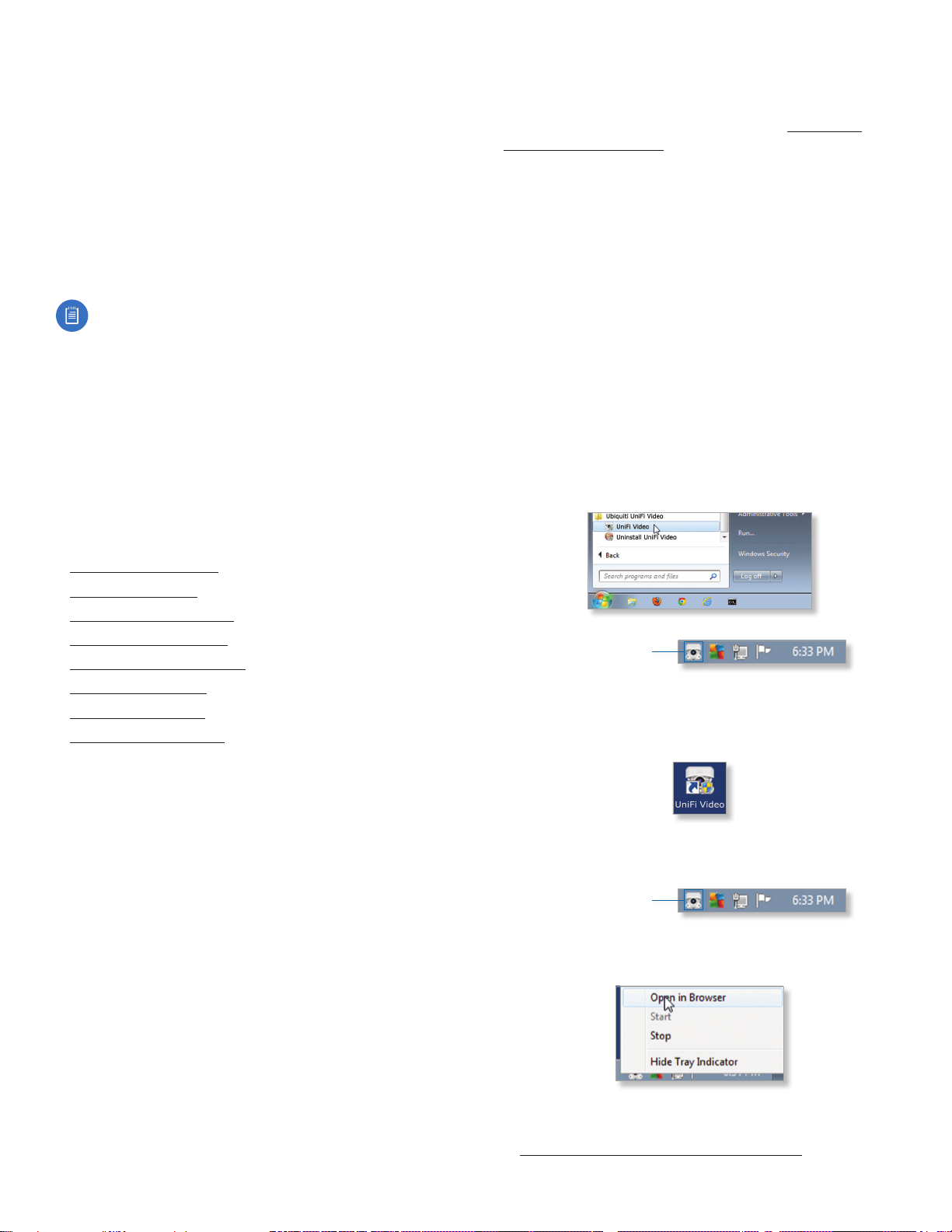
a. Click the Start menu and select All Programs from
the popup menu.
b. Scroll down to Ubiquiti UniFi Video and click the
folder name once to expand its contents.
c. Select Ubiquiti UniFi Video. This will launch the
UniFi Video tray icon in the bottom right corner of
the Windows taskbar.
UniFi Video Tray Icon
‑ Desktop Icon
a. Double‑click the icon shown below to start the UniFi
Video service.
b. The UniFi Video tray icon will appear in the bottom
right corner of the Windows taskbar.
UniFi Video Tray Icon
2. Click the UniFi Video tray icon and select Open in
Browser from the pop‑up menu.
The UniFi Video software will open in your browser. The
first time you use the software, set up the NVR as detailed
in “Windows UniFi Video Setup” on page 5.
5
Chapter 1: InstallationUniFi Video User Guide
Ubiquiti Networks, Inc.
Windows UniFi Video Setup
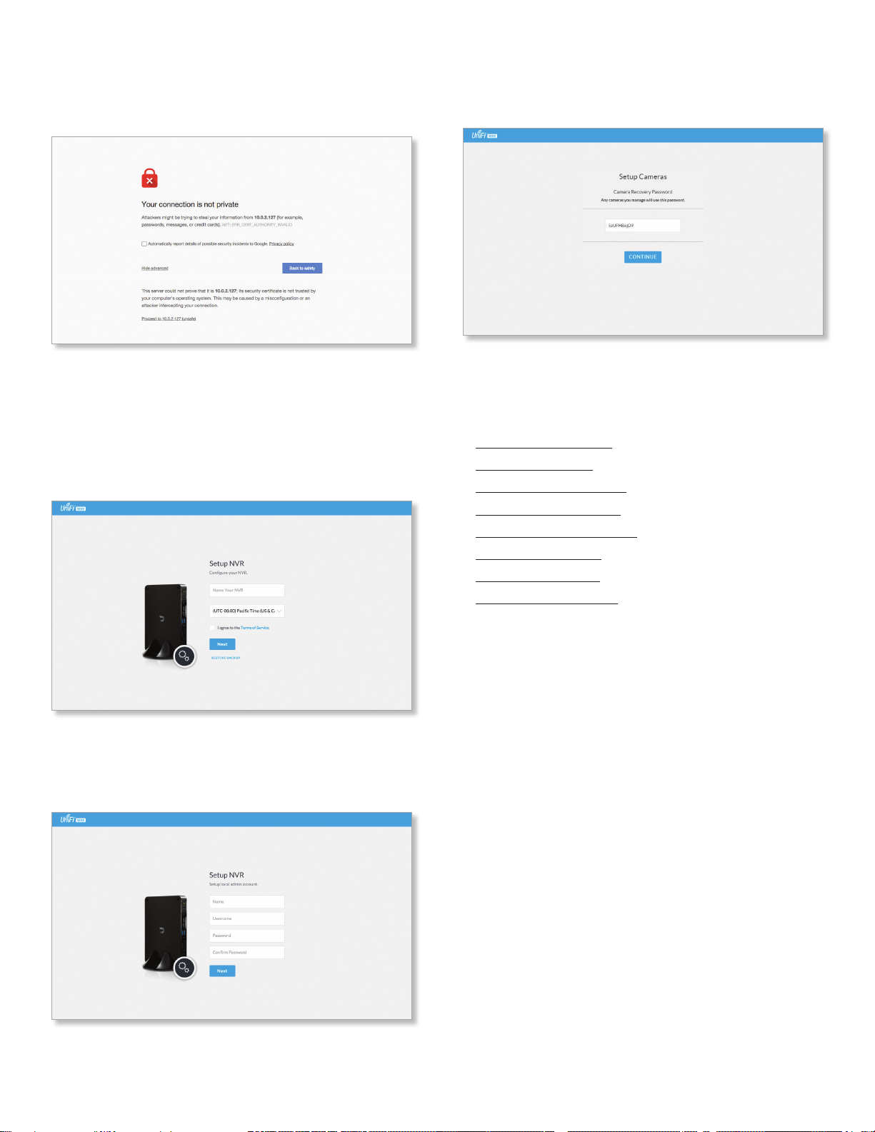
1. If you receive a security warning, click Advanced, and
then click Proceed to <NVR IP address>.
2. The Setup NVR window will appear:
a. Enter a name for the NVR.
b. Specify your time zone.
c. Select I agree to the Terms of Service (click Terms
of Service to view the Terms of Service).
d. Click Next.
3. Create an Admin account by entering a Name,
Username, and Password (enter twice to confirm). This
information will be used to log in and access the UniFi
Video Controller system. Click Next.
4. The Setup Cameras window will appear. Enter a
password (twice to confirm) to be used to manage your
cameras.
5. When the firmware update is complete, “Setup
Complete” is displayed. Click Go to Cameras.
Proceed to the appropriate chapter for information on
using the UniFi Video Management software:
• “Cameras” on page 7
• “Map” on page 13
• “Live View” on page 15
• “Timeline” on page 17
• “Recordings” on page 21
• “Alerts” on page 23
• “Users” on page 25
• “Settings” on page 29

6
Chapter 1: Installation UniFi Video User Guide
Ubiquiti Networks, Inc.
Enabling Cloud Access from Existing
Installations
If you have upgraded to UniFi Video version 3.8 from an
older version, follow these instructions to enable cloud
access to your UniFi Video Management system:
1. Launch the UniFi Video Management software, as
described in “Launching UniFi Video” on page 4.
2. Click Settings to open the Settings page.
3. Click Connect to My Ubiquiti Account.
Note: If you do not have a Ubiquiti account, you
must create one before continuing. Create a new
Ubiquiti account as follows:
1. Go to https://video.ubnt.com
2. Click Register.
3. Enter the requested information. Click
Register.
4. A verification e‑mail will be sent to the e‑mail
account you specified in the previous step.
Open the e‑mail and click the link to verify your
account.
5. Enter your Username and Password of your Ubiquiti
account to connect the account to the NVR.
6. You will now be able to access your UniFi Video
Management system from https://video.ubnt.com

7
Chapter 2: CamerasUniFi Video User Guide
Ubiquiti Networks, Inc.
Chapter 2: Cameras
On the Cameras page, you have the option to view all
cameras (default), a selected group of cameras, or a single
camera, depending on your search criteria. The Search
option will narrow down the list of cameras displayed as
you type characters into the Search text field, eliminating
the ones that don’t match your search criteria. The
searchable columns are Name, Host, and MAC Address.
12
Each camera will be categorized as Managed or
Unmanaged and the number in the upper left corner
indicates how many cameras you have per category. In
this example, there are 12 Managed cameras.
Cameras listed under the Managed tab have been added
to the UniFi Video management system. Cameras listed
under the Unmanaged tab have not been configured or
added to the UniFi Video management system yet, or have
been unmanaged.
To change the status of a camera from Unmanaged to
Managed, follow these steps:
1. Click Unmanaged to see a list of unmanaged cameras.
2. Click a camera to view its details. Refer to
“Configuration” on page 12.
3. Enter the username and password for the selected
camera and click Manage.
Once you’ve finished adding the unmanaged cameras,
click Managed to return to the Managed cameras view.
For each camera, the Managed camera view lists the Name,
Host (address), MAC Address, Last Recording, and Link State.
Click a column heading to sort the list by that column;
click again to reverse the sort order.
Name Displays the local device name and a thumbnail
image of the camera.
Host Displays the local host IP address assigned to each
specific camera.
MAC Address Displays the MAC Address of the camera.
Each camera has its own unique hardware address.
Last Recording Displays how long it has been since a
camera recorded something based on its recording mode.
Refer to “Recording” on page 11.
Link State Displays the following information for the
currently selected camera:
• Connection type:
• Wired or Wireless
Green icon: Camera is connected
Gray icon: Camera is disconnected
• Connection state: Connected, Disconnected, Rebooting,
Unauthenticated
• Connection speed in Mbps (wired cameras only)
• Connection quality in dBm (wireless cameras only)
8
Chapter 2: Cameras UniFi Video User Guide
Ubiquiti Networks, Inc.
Live Feed Click
LIVE FEED
to view a live feed of the
selected camera.
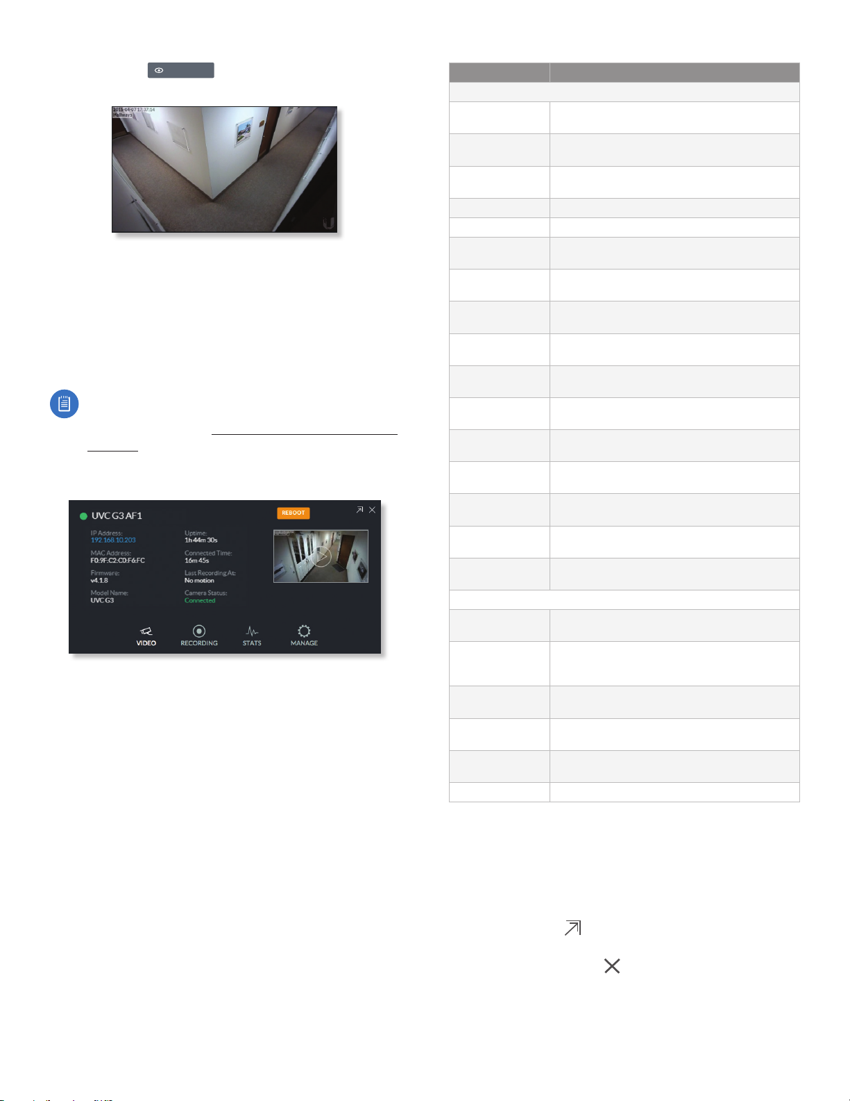
Camera Details Window
Click a camera to view the details window and display its
IP Address, MAC Address, Model Name, Uptime, Connected
Time, Last Motion At, and Status. To select more than one
camera, click the checkbox next to each camera. To select
a range of cameras, press and hold Shift, and then click the
first and last cameras in the range.
Note: To select a camera, do not click the Host
column (doing so brings up the camera’s standalone
web UI, described in “Using Standalone Mode” on
page 45).
The Camera Details window also has four clickable tabs:
Video, Recording, Stats, and Manage.
IP Address Displays the local IP address of the camera.
MAC Address Displays the MAC (Media Access Control)
Address of the camera. Each camera has its own unique
hardware address.
Firmware Displays the version of the firmware currently
installed on the camera.
Model Name Displays the model name of the camera.
Uptime Displays the amount of time that a camera has
been running without interruption or since last reboot.
Connected Time Displays the amount of the time the
camera has been connected.
Last Recording At Displays the last date and time that
a recording took place for the camera you are currently
viewing.
Status Displays the current status of the camera.
Indicators are Connected, Disconnected, or Rebooting.
If Disconnected is displayed, a message summarizing
the reason for the disconnection is also displayed. The
following table describes these messages in detail:
Message Detailed Description
Error Conditions
Camera Database
Failure
UniFi Video database corruption was detected
during a camera firmware upgrade.
Unauthorized
Access
The camera username and/or password were
rejected when attempting to manage a camera.
Authentication
Failed
The camera and/or the controller failed during
their mutual authentication process.
Upgrade Failed The camera firmware upgrade failed.
Connection Lost The controller lost its connection with the camera.
Provisioning
Failed
The controller failed to provision the camera
during the camera management process.
Video Settings
Failed
The controller failed while applying video settings
during the camera management process.
Password Sync
Failed
The controller failed while updating the camera
password.
Analytics Settings
Failed
The controller failed while applying analytics
settings during the camera management settings.
Network Status
Settings Failed
The controller failed while applying network
settings during the camera management settings.
Controller Bad
Request
The controller sent a bad request to the camera.
Connection
Timeout
The connection timed out while the controller
was trying to send the camera a message.
Camera Error An internal camera error was reported back to the
controller.
Firmware Not
Supported
The controller detected an unsupported firmware
installed on a camera it is trying to manage.
No Route To Host The controller is unable to reach the camera from
its IP address.
Certificate
Mismatch
The controller has detected a certificate mismatch
during the authentication process.
Informational
Upgrade In
Progress
The controller disconnected the camera due to
the camera firmware upgrade being initiated.
Rebooting The controller disconnected the camera due to
the user rebooting the camera from the UniFi
Video web application.
Updating
Password
The controller has requested a password update
to the camera.
Camera
Umanaged
The controller un-managed the camera.
Camera
Discovered
The controller discovered a camera.
Camera Initialized The controller is initialized and can be managed.
Reboot (Functional for administrators only.) Click
Reboot to reboot the camera. The camera’s status
will temporarily change from Connected to Rebooting,
and then Disconnected before coming back online as
Connected. Rebooting a camera will also reset the Uptime
and Connected Time fields in the details window.
Hide Details Click to hide the camera details. Click it
again to reveal the camera details.
Exit Camera Detail Click to close and exit the Camera
Details window.
Live Stream Click the image thumbnail in the upper-right
corner to display the live stream window of the selected
camera.
9
Chapter 2: CamerasUniFi Video User Guide
Ubiquiti Networks, Inc.
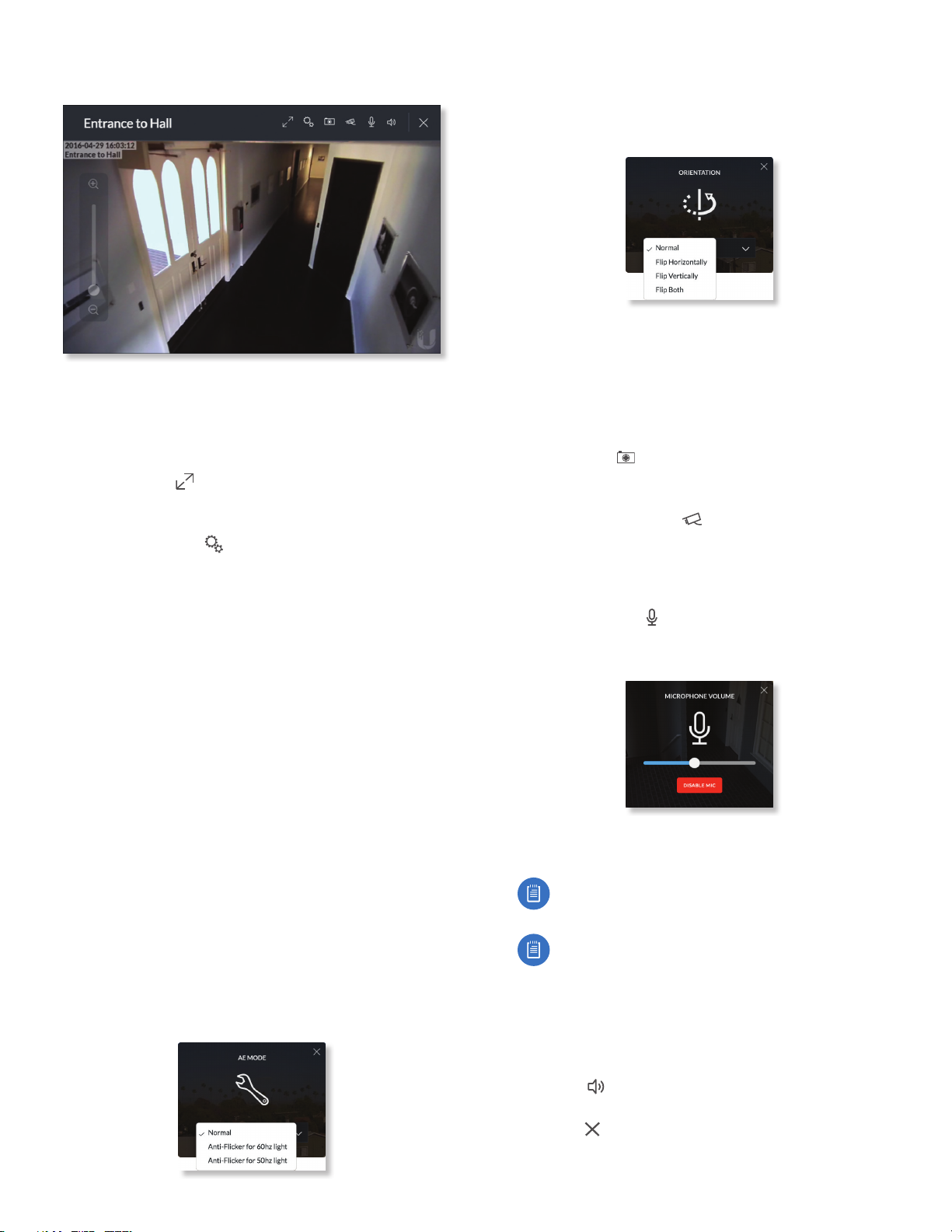
Live Stream Window
The Live Stream window above has a menu bar in the
upper right corner that allows you to view the camera feed
in Full Screen, adjust the Image Settings, take a Snapshot
of the live feed, change the Camera Resolution, and adjust
the volume controls for audio input and output.
Full Screen Click to view the live stream window in
full screen. Press esc on your keyboard to exit full screen
mode and return to the window view.
Image Settings Click to view the imaging drop-down
menu that allows you to change the live view image
settings for each of the following:
• Brightness Adjust the brightness of the live view image
by dragging the slider control to the left or right.
• Contrast Adjust the contrast of the live view image by
dragging the slider control to the left or right.
• Hue Adjust the hue of the live view image by dragging
the slider control to the left or right.
• Saturation Adjust the saturation of the live view image
by dragging the slider control to the left or right.
• Denoise Adjust the noise level of the live view image
by dragging the slider control to the left or right.
• Sharpness Adjust the sharpness of the live view image
by dragging the slider control to the left or right.
• WDR Adjust the WDR (Wide Dynamic Range) sensitivity
of the live view image by dragging the slider control
to the left or right. WDR helps create better image and
video detail in frames that contain both light and dark
areas that would otherwise be over- or underexposed.
• AE Mode Choose AE (Auto Exposure) mode for the
live view images by selecting Normal, Anti-Flicker for
60Hz light, or Anti‑Flicker for 50 Hz light from the
drop-down menu. The default is Normal.
• Orientation Change the way an image is displayed
in the live stream window by selecting Normal, Flip
Horizontally, Flip Vertically, or Flip Both from the
drop-down menu. The default setting is Normal.
• Infrared The infrared filter can be changed for the live
view image by selecting On or Off from the drop-down
menu. The default setting is Auto.
• Zoom Adjust the optical zoom (if equipped) from 1x up
to 3x
• Focus Adjust the focus mechanism (if equipped)
Snapshot Click to take a snapshot of the live video
image and save it to a file. The file name will have the
following format: <camera name><date and time>.jpg
Camera Resolution Click to set the live view image
resolution to High, Medium, or Low. The default setting
is Auto, which allows the camera to choose the best
supported setting automatically.
Microphone Volume (Option available for cameras that
support audio.) Click to adjust the microphone volume
used to record audio input for a recording. You can adjust
the volume by dragging the slider horizontally.
• Disable Mic To disable the microphone, click Disable
Mic, and then click Yes, Disable Microphone to confirm.
Note: To re-enable the microphone, the camera
must be set to its factory default settings.
Note: UniFi Video Cameras can be reset to factory
defaults using one of the following methods:
• Camera’s WEB UI
• SSH
• Camera’s Physical Reset Button
Audio Output (Option available for cameras that support
audio.) Click to mute or unmute the live view audio
feed of the camera.
Close Click to close the Camera Details window and
exit back to the home screen.

10
Chapter 2: Cameras UniFi Video User Guide
Ubiquiti Networks, Inc.
Video
Resolution
Resolution in this section refers to video output quality
expressed in total pixels: image length (horizontal) x
image height (vertical).
Override Suggested Settings Click to enable or disable
manual override of the selected camera’s resolution
settings. With Override Suggested Settings set to ON, you
will be able to adjust FPS (frames per second, also known
as frequency), and Bitrate, for the video output at each
resolution: High, Medium, and Low.
Note: The displayed resolution (n X n) for High,
Medium, and Low is hardware-dependent.
High/Medium/Low (n X n)
FPS Drag the slider to choose a frame rate for the selected
camera’s video output resolution.
Bitrate Drag the slider to choose a bitrate for the selected
camera’s video output resolution. The bitrate is selectable
in 100Kbps increments.
On Screen Display
Override Message Click to enable or disable message
override. When enabled, enter the text, for example, Rob’s
Office, that you want to be displayed on the video feed for
the selected camera.
Timestamp Overlay Click to enable or disable the
timestamp from appearing on the live video feed.
Watermark Click to enable or disable the visibility of the
watermark on the live video feed of the selected camera.
Accessories
Enable Status LED (Available on UVC-G3 Dome and
UVC-G3-Micro.) Click to enable or disable the status LED
on the camera.
Enable Speaker Enable for two-wa communication
Enable Ssytem Sounds Enables or disables informational
tones, such as WiFi or controller disconnects.
RTSP/RTMP/RTMPS Services
RTSP Service (Real Time Streaming Protocol), RTMP Service
(Real Time Media Protocol), and RTMPS Service (Real Time
Media Protocol over SSL) are network protocols designed
for facilitating the playback of media files. These settings
allow you to enable RTSP/RTMP/RTMPS service(s) for each
of the camera’s resolutions (High, Medium, and Low).
Note: The displayed resolution (n X n) for High,
Medium, and Low is hardware-dependent.
Click to enable/disable the toggle switch ON or OFF for
each resolution under the specified service.

11
Chapter 2: CamerasUniFi Video User Guide
Ubiquiti Networks, Inc.
Recording
Configuration
Record Mode Allows you to define the recording mode of
the selected camera.
• Don’t change This option only appears when multiple
cameras are selected. Choosing this option keeps the
cameras in their current recording mode.
• Don’t record Nothing will be recorded by the camera.
• Always record Enables the camera to record all the
time, regardless if there is motion detected or not.
• Record only motion All captured images are analyzed
and only recorded when motion is detected.
• Record on schedule Allows you to set up a specific
recording schedule for each individual camera.
Choosing this Record Mode will display a Schedule
option. Click the Schedule drop-down menu to create a
new schedule or select from a list of existing schedules.
- New Schedule To create a new recording schedule,
click and drag a block of time on each day you would
like the camera to record. When you are finished,
click Save. You can also update or delete an existing
schedule by clicking to view it in edit mode.
Resolution Choose one of the following three resolutions
to use for the selected camera: High, Medium, or Low.
Note: The displayed resolution for High, Medium,
and Low is hardware-dependent.
Motion Detection
Zones Click Configure to edit motion zones for the
selected camera. This option does not appear if multiple
cameras are selected, as zones are configured individually.
Minimum Motion Event Trigger Drag the slider control
left or right to set the minimum duration (0 to 10 seconds)
that motion must take place to trigger recording.
(X Seconds Before -> Actual Motion -> X Seconds After Motion)
End Motion Event Delay The number of seconds that
must elapse before a camera considers motion to have
stopped.
Seconds To Record Before Enter the number of seconds
you want UniFi Video to record before the triggering
motion occurs on the selected camera.
Seconds To Record After Enter the number of seconds
you want UniFi Video to record after the triggering motion
occurs on the selected camera.
Configuring a Zone
Adjustment Points
By default, the initial zone for each camera is the entire
viewing area captured in the live feed window. Click
and drag the Adjustment Points from each corner of the
window to the perimeter of the area you would like to
define as your zone. Only motion within this zone will
trigger recording.
Click to test the zone you just created and adjust
the sensitivity using the Sensitivity Slider control. Image
trails will appear when motion is detected and the
sensitivity level and motion spikes will appear in the
bottom right corner of the camera feed. The sensitivity
level (from 0 to 100) is shown in the box to the right of the
slider control. As various degrees of motion occur, you’ll
see different level spikes. Adjust the sensitivity to a level
that best suits your needs. Motion spikes that exceed
the defined sensitivity threshold will be recorded when
motion recording is enabled. Click Test Zone again to stop
the test.

12
Chapter 2: Cameras UniFi Video User Guide
Ubiquiti Networks, Inc.
Sensitivity Level
Motion Spike
Motion Trails
Sensitivity Slider Sensitivity Level (0-100)
Click to refresh the camera image that appears in
the zone preview.
Use this button to delete the current zone. Click
an area of the camera feed to define another zone
after deleting the existing zone.
Entry Door
Enter a name or brief description of the zone you
are creating, in the text field provided. In this
example, Entry Door is used.
Click Save when you are done configuring and
naming your new zone.
Click Revert to cancel all changes and restore the
previous settings.
Status
CPU (% Utilization) Displays the camera’s CPU utilization
recorded over 24 hours with high, low, and average points
highlighted. Red indicates the highest point, green is the
average, and blue is the lowest point during sampled
intervals.
Memory (% Utilization) Displays the percentage of the
camera’s memory utilization over a 24-hour period.
Network (Kbytes/sec) Displays the network traffic for the
selected camera over the last 24 hours. Graph is expressed
in kilobytes per second.
Disk (Mbytes) Displays the amount of disk usage for the
selected camera over the last 24 hours. Graph is expressed
in total megabytes.
Manage
Configuration
Host Displays the local IP address configured for the
camera you are currently viewing.
Alias Displays the device name configured for the live
feed window for each camera. This is different from the
name described for “On Screen Display” on page 10.
Controller Settings
Controller Host The IP address that the camera should
use to communicate with the controller. This setting is
typically used in environments where the UniFi Video
server has multiple active network interfaces.
Controller Port The port that the camera should use to
communicate with the controller. Beginning with version
3.8.0, this has been separated from the web management
port (default 7443) for security purposes.
Unmanage
Click Unmanage if you no longer want to manage
the selected camera. If you wish to remove unlocked
recordings for that particular camera as well, check the
box labeled Remove Unlocked Recordings.
13
Chapter 3: MapUniFi Video User Guide
Ubiquiti Networks, Inc.
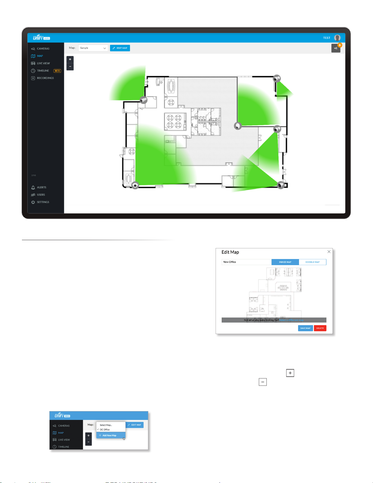
Chapter 3: Map
The Map page allows you to upload custom map images
of your site or floor plan, including aerial locations from
Google Maps™for a visual representation of your camera
layout.
The map also indicates if motion has been detected on
a camera. The color of each camera’s field of view varies
from red (motion currently detected) to green (no recent
motion).
Defining a Map
You can add an image you’ve created as a map image
or use Google Maps to generate an image for use as a
background.
Image Map
To add a custom map, you must first create the image
using an illustration, image editing, or blueprint
application that exports .jpg, .gif, or .png file formats.
Once you’ve created the map, you can upload it to the
UniFi Video software by performing the following steps:
1. Click Add New Map in the Map drop‑down menu.
2. Enter a map name in the Enter new map name field and
click Image Map.
3. Select the file to use as a map (valid file formats are
.jpg, .gif, and .png). Click Open.
4. Click Add Map.
5. Zoom in on the map using the button on the left.
Zoom out using the button.
14
Chapter 3: Map UniFi Video User Guide
Ubiquiti Networks, Inc.
6. Click the button in the upper right corner to bring
up a list of cameras for placement. Drag the camera
from the Cameras list on the right to the appropriate
location on the map. The camera will appear in the area
it was placed.
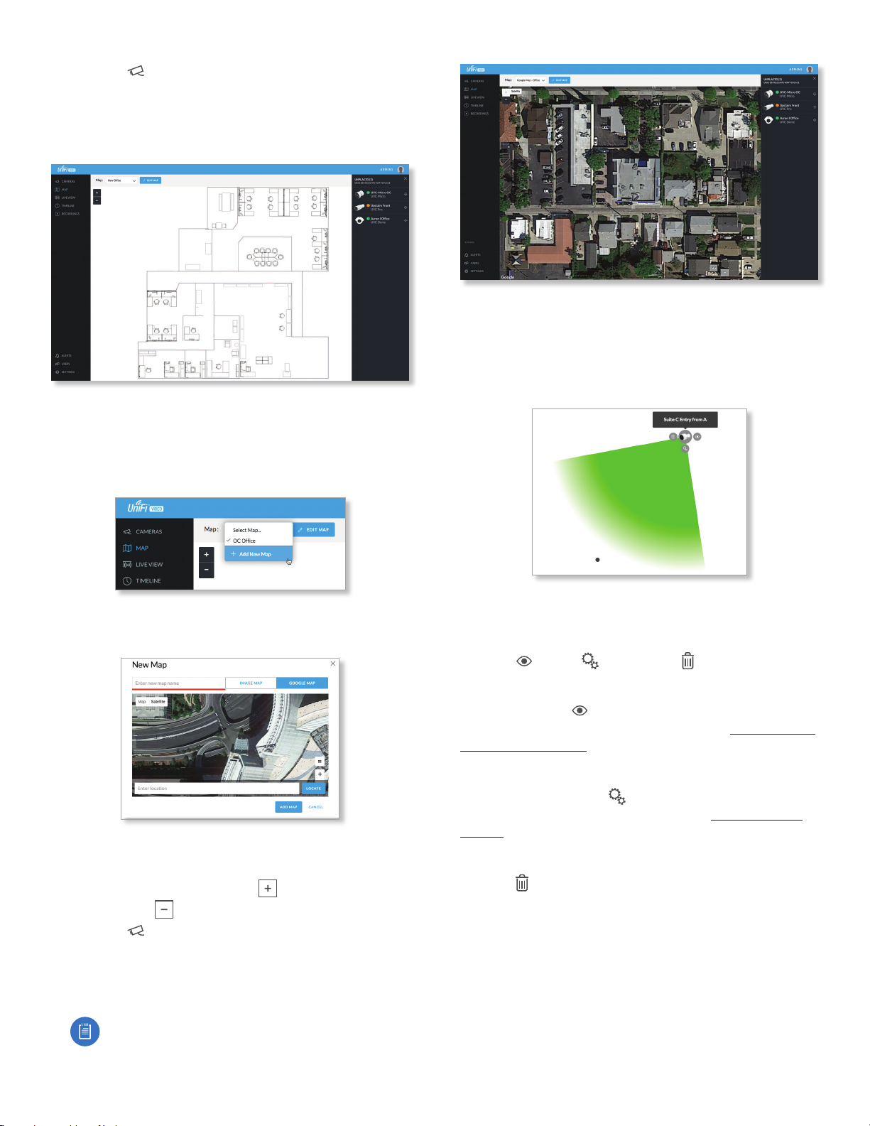
Google Map
To create a custom map using Google Maps, perform the
following steps:
1. Click Add New Map in the Map drop‑down menu.
2. Enter the desired address in the Enter location field and
click Locate.
3. Enter a map name in the Enter new map name field and
click Add Map.
4. Zoom in on the map using the button and zoom
out using the button.
5. Click the button in the top right corner to bring
up a list of cameras for placement. Drag the camera
from the Cameras list on the right to the appropriate
location on the map. The camera will appear in the area
it was placed.
Note: When using Google Maps, you must supply
an API Key in the Maps Settings box under
Settings.
Camera Placement
Camera thumbnails can be placed on the map to show the
location of your cameras. To reposition a camera on the
map, click and hold the Camera thumbnail and then drag
the camera to another location on the map.
Click and drag the black dot to adjust the camera’s
direction and field of view.
Click the Camera icon to reveal additional options:
LiveFeed , Details , and Remove .
Live Feed
Click the Live Feed icon to bring up the camera’s Live
Stream window. The details are described in “Live Stream
Window” on page 9.
Details
Click the Camera Details icon to bring up the Camera
Details page. The details are described in “Cameras” on
page 7.
Delete
Click the icon to remove the camera from the map.
15
Chapter 4: Live ViewUniFi Video User Guide
Ubiquiti Networks, Inc.
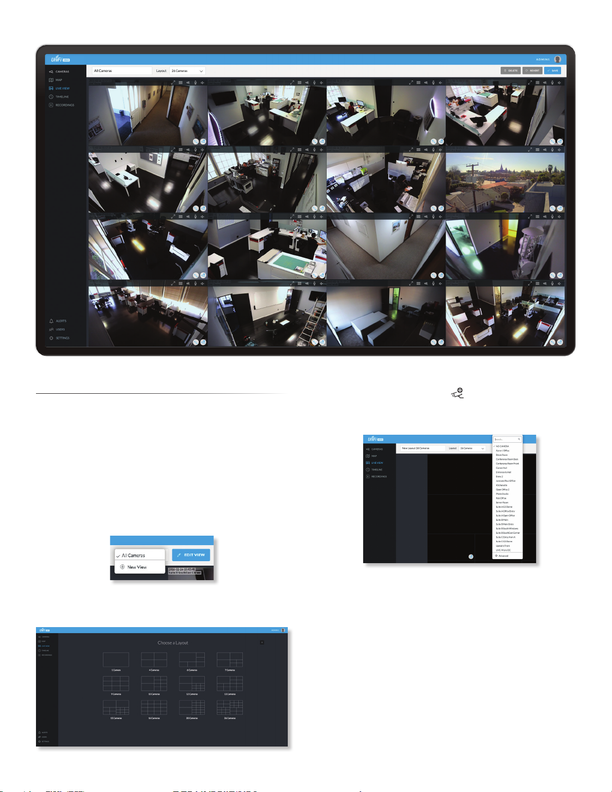
Chapter 4: Live View
You can monitor multiple camera feeds through a
single view layout using the Live View page. There are 12
pre‑defined templates that support up to 26 cameras. Live
View allows you to select which camera layout to use and
which video feeds to display in that particular layout.
Create a New View
To create a custom Live View, follow these steps:
1. Click the drop‑down box at the top left of the window.
Click New View.
2. Select a layout by clicking one of the templates in the
Choose a Layout window.
3. Do the following for each of your cameras:
a. Click the Camera Select icon in the bottom right
corner of a video feed area to display the list of
available cameras.
b. Assign the camera to the video feed area using one
of the following methods:
• Select a camera from the list.
• Search for a camera name (or part of a name) by
entering it into the Search field at the top of the list.
• Select Advanced at the bottom of the list to open
the Advanced dialog. Then select the camera from
the drop‑down list and select the Cycle On setting:
Motion or Time Interval.
4. The cameras will appear in the areas of the layout
and you will see their live video feeds in the Live View
window.
16
Chapter 4: Live View UniFi Video User Guide
Ubiquiti Networks, Inc.
5. To view or modify the details of any camera in your
layout, click the Configure icon and refer to “Camera
Details Window” on page 8.
6. Save the layout by entering a name or brief description
in the View Name text field and clicking Save on the
right side of the menu bar. Or, click Delete to delete the
view without saving it.
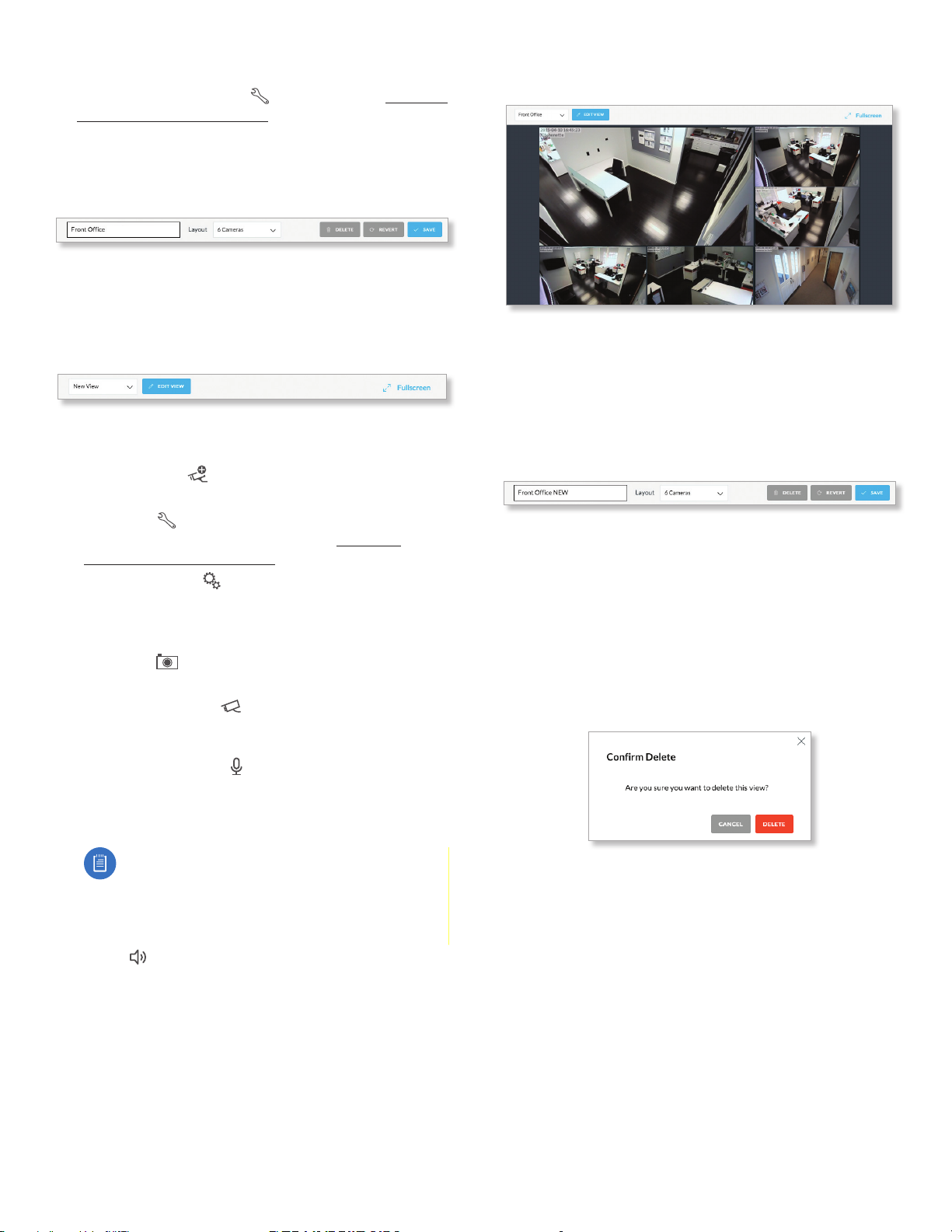
Edit a View
To edit an existing Live View, follow these steps:
1. Display the view that you want to edit by selecting it
from the drop‑down list. Then click Edit View.
2. Edit the view using the icons displayed in the video
feeds of the layout:
‑ Camera Select Click this icon to assign a different
camera to the video feed.
‑ Configure Click this icon to display the camera
details window (described in detail in “Camera
Details Window” on page 8).
‑ Camera Settings Click this icon to configure
various image settings such as Brightness, Contrast,
Hue, Saturation, Denoise, Sharpness, WDR, AE Mode,
Orientation, and Infrared.
‑ Snapshot Click this icon to download a snapshot
of the current view.
‑ Camera Resolution Click this icon to set the
camera’s resolution to one of the following settings:
Auto (Medium), High, Medium, Low.
‑ Microphone Volume Click this icon to configure
the camera’s microphone. Drag the slider to the left or
right to adjust the volume for recording audio input,
or click Disable Mic to disable the microphone.
Note: If the microphone is disabled, the volume
icon will not appear in the toolbar. To re‑enable
the microphone, you will have to manually reset
the camera to factory defaults by pressing its
reset button.
‑ Audio Click this icon to mute or unmute the audio.
3. Save the edited layout by clicking Save on the right
side of the menu bar. Click Revert to cancel the
changes you’ve made to the view.
Renaming a View
You can rename an existing view or layout by performing
the following steps:
1. Click the drop‑down list of existing camera layouts and
select the view you want to rename. In this example,
we will use Front Office.
2. Click Edit View next to the camera layout you selected
and enter a new name for the layout.
3. Click Save to save the changes you’ve made to the
view. Click Revert to cancel the changes you’ve made
to the view.
Deleting a View
You can delete an existing view or layout by performing
the following steps:
1. Click the drop‑down list of existing camera layouts and
select the view you want to delete.
2. Click the Delete button to remove a view.
3. When prompted, click Delete to confirm.
Other manuals for UVC-G3-AF
1
Table of contents
Other Ubiquiti DVR manuals


Popular DVR manuals by other brands

Avermedia
Avermedia AverDigi MXR6004 mini user manual

Dahua Technology
Dahua Technology IVSS user manual

GE
GE Calibur DVMR Triplex eZ user manual

LJD Digital Security
LJD Digital Security Colossus Pro user manual

March Networks
March Networks 8724 V Tribrid NVR installation guide

Motorola
Motorola DCX3400 Series user guide


