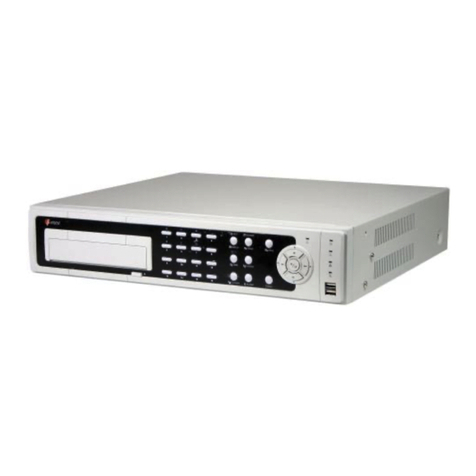
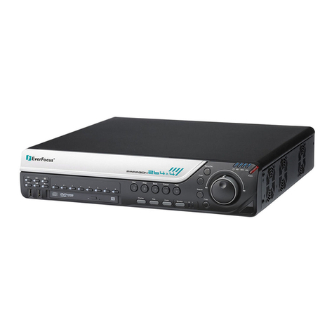
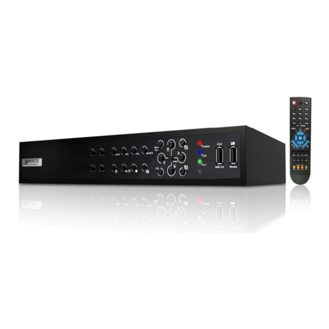
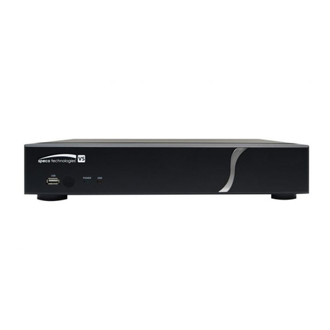
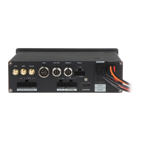
3vr P-Series SmartRecorder User manual

3VR SmartRecorder
Basic Installation Guide
3VSR-BICG606-R1
3VR Security, Inc. 475 Brannan Street, Suite 430, San Francisco, CA 94107 Tel: 415.495.5790 • Sales: 415.513.4611 • Fax: 415.495.5797 • Email: [email protected] • www.3VR.com
3VR and the 3VR logo are either trademarks or federally registered trademarks of 3VR Security, Inc. © 2009 3VR Security, Inc.
3VR Software Version 6.0.6

3VR SmartRecorder
Basic Installation Guide
Product Diagrams
P-Series SmartRecorder 6
S-Series SmartRecorder 7
E-Series SmartRecorder 8
M-Series SmartRecorder 9
Chapter 1: Installing a 3VR SmartRecorder
Step 1: Inspect and Mount Hardware 12
Step 2: Log In to the SmartRecorder 20
Step 3: Check System Software Version 21
Step 4: Rename the SmartRecorder 22
Step 5: Set the System Time Zone 23
Step 6: Set the System Date and Time 24
Step 7: Congure Network Settings 25
Step 8: Connect Analog Cameras 27
Step 9: Verify Video Quality 30
Chapter 2: Conguring a 3VR SmartRecorder
Step 1: Congure Channels for Analog Cameras 34
Step 2: Congure Outgoing Email Settings 36
Step 3: Install Plug-ins (Optional) 37
Step 4: Congure Event and Video Storage Settings 39
Step 5: Dene the Schedule for Recording Settings 40
Step 6: Dene the Schedule for Bandwidth Control 41
Step 7: Enter System License Keys (Optional) 43
Step 8: Set Install/Certication Date 44
Step 9: Run the Installation Report 45
Appendix A: Image Guidelines for Facial Recognition 49
Appendix B: Connecting a Laptop to a 3VR SmartRecorder 63
Appendix C: Updating Software on a 3VR SmartRecorder 68

3VR Security Inc. (hereinafter “3VR”) provides this manual
“AS IS,” for informational use only, without warranty of any
kind, expressed or implied, including but not limited to
representations or warranties with respect to the contents
hereof and specically disclaims any implied warranties
of merchantability or tness for any particular purpose.
3VR reserves the right to revise this manual and to make
changes in its content without obligation to notify any
person or organization of such revision or change. In no
event shall 3VR Security, Inc., its Directors, Ocers, or
Employees be liable for any indirect, special, incidental,
or consequential damages (including damages for loss of
prots, loss of business, loss of use or data, interruption of
business and the like), even if 3VR has been advised of the
possibility of such damages arising from any defect or error
in this manual or product.
3VR Security Inc., 3VR, and the 3VR logo are trademarks
of 3VR. 3VR may have patents, patent applications,
trademarks, copyrights, or other intellectual property
rights covering subject matter in this document. Except
as expressly provided in any written license from 3VR,
the furnishing of this document does not give you any
license to these patents, patent applications, trademarks,
copyrights, or other intellectual property. Other products,
trademarks or names appearing in this document may or
may not be trademarks, licensees, or copyrights of their
respective owners and are used only for identication or
explanation and to the owners’ benet, without intent to
infringe.
The persons depicted in this document are, to the best
of 3VR’s knowledge, employees of 3VR or casual passers-
by, and are neither suspected of any crime nor have they
been convicted of any crime. The incidents portrayed
and the names used in this document are ctitious and
any resemblance to the names, character, or history of
any actual person, living or deceased, is coincidental and
unintentional.
3VR SmartRecorder Installation and Conguration Guide
© 2004 - 2009 3VR Security, Inc.
Release 6.0.6, September 2009
3VSR-BICG606-R1

4

Product Diagrams
P-Series SmartRecorder 6
S-Series SmartRecorder 7
E-Series SmartRecorder 8
M-Series SmartRecorder 9
5

Product Diagrams
P-Series SmartRecorder
Front view
Front interior view
Back view
system status indicator
front latch
hard drive bay 1 hard drive bay 2
hard drive bay 3 hard drive bay 4
power button USB ports
power cable socket
fan
mouse
port
unused
parallel
port
external
I/O port
video input
ports
unused
audio input
ports
keyboard
port
RS-232
serial
port
monitor
port
primary
Ethernet
port
BNC video
output
RS-422/485
serial port
secondary
Ethernet
port
USB
ports
RS-232 serial
port
DVI
output
63VR SmartRecorder Installation and Conguration Guide

Product Diagrams
S-Series SmartRecorder
Front view
Back view
mouse
port
keyboard
port
monitor
port
RS-232
serial
port
USB
ports
unused
parallel
port
primary
Ethernet port
SpotMonitor
adapter port
video input
ports
digital output
port
RS 422/485
serial port
digital
input port
power
jack
hard drive
activity
indicator
power
button
power
indicator
Product Diagrams 7

Product Diagrams
E-Series SmartRecorder
2
AB
CD
Front view
Back view
DVD drive USB port
hard drive
activity
indicator
power
button
reset
button
power cable socket USB ports Ethernet port video input ports
monitor
port
unused
parallel
port
keyboard
port
mouse
port
fan
power
indicator
rack mount ear rack mount ear
83VR SmartRecorder Installation and Conguration Guide

Product Diagrams
M-Series SmartRecorder
Front view
Back view
Product Diagrams 9

10

Chapter 1:
Installing a 3VR SmartRecorder
Step 1: Inspect and Mount Hardware
P-Series SmartRecorder and SmartSearch NVR 12
S-Series SmartRecorder and SmartSearch NVR 14
M-Series SmartRecorder 16
E-Series SmartRecorder and SmartSearch NVR 18
Step 2: Log In to the SmartRecorder 20
Step 3: Check System Software Version 21
Step 4: Rename the SmartRecorder 22
Step 5: Set the System Time Zone 23
Step 6: Set the System Date and Time 24
Step 7: Congure Network Settings 25
Step 8: Connect Analog Cameras
P-Series SmartRecorder 27
S-Series SmartRecorder 28
M-Series SmartRecorder 28
E-Series SmartRecorder 29
Step 9: Verify Video Quality 30
11

Step 1:
Inspect and Mount Hardware
Follow the instructions for your SmartRecorder model:
SmartRecorder P-Series and P-Series SmartSearch NVR This Page
SmartRecorder S-Series Page 14
SmartRecorder M-Series Page 16
SmartRecorder E-Series and E-Series SmartSearch NVR Page 18
Two - Four Video Cables
(depends on system configuration)
5
6
7
8
1
2
3
4
Power Cable
Front-Panel Hinges
Front Panel
Keyboard/Mouse
Two Rack-mount Ears
Alarm Input/Output Adapter
Installation and Resource CD
One or Two Video Cables (depends on system conguration)
The following items should be found in the P-Series accessory box*:
*No video cables included with SmartSearch NVR
Two - Four Video Cables
(depends on system configuration)
5
6
7
8
1
2
3
4
Power Cable
Front-Panel Hinges
Front Panel
Keyboard/Mouse
Two Rack-mount Ears
Two Rack Mount Ears
and Six Screws
P-Series SmartRecorder and SmartSearch NVR
12 3VR SmartRecorder Installation and Conguration Guide

Inspect the site to determine the appropriate location for the SmartRecorder installation. Ensure that the 1.
environmental conditions listed below are satised; mounting the unit in a location which exceeds the
conditions listed below will void its warranty.
Environmental Conditions
Operating Temperature 5° to 35°C (41° to 95°F)
Heat Dissipation 1360 BTU/Hour
Humidity 5% to 95% RH (noncondensing)
Storage Conditions -10° to 60°C (14° to 140°F)
Maximum Operating Altitude 3,048 m (10,000 ft)
Clearance A minimum of 4” clearance in both front and rear of unit.
Connect the power cable.4.
Connect a network cable to the 5. left (primary)
Ethernet port.
If you will be connecting to the SmartRecorder with a monitor, mouse, and keyboard:
Once a suitable location has been identied, 2.
attach the rack-mount ears to the server using
the included screws.
Mount the unit in the equipment rack or shelf.3.
Connect the keyboard to the purple 6.
port and the mouse to the green
port.
Connect a monitor to the monitor 7.
port.
Press the power button on the front 8.
of the unit.
If you will be conguring the system with a laptop and network cable or USB network adapter:
See Appendix B: Connecting a Laptop to a 3VR SmartRecorder for complete instructions.
primary
Ethernet port
Chapter 1: Installing a 3VR SmartRecorder 13

Two or Four Video Cables
5
6
7
8
2
3
1
4
5
6
7
8
2
3
1
4
A
A
A
A
Two Alarm Input/Output Adapters One SpotMonitor Adapter
Two Wall-mount Brackets and Four Screws Power Supply
The following items will be found in the S-Series shipping container*:
3VR SmartRecorder S-Series
Installation and Resource CD
One or Two Video Cables (depends on system conguration)
*No video cables included with SmartSearch NVR
S-Series SmartRecorder and SmartSearch NVR
14 3VR SmartRecorder Installation and Conguration Guide

Inspect the site to determine the appropriate location for the SmartRecorder installation. Ensure that 1.
the environmental conditions listed below are satised; mounting the SmartRecorder in a location which
exceeds the conditions listed below will void the warranty.
Environmental Conditions
Operating Temperature 5° to 49°C (41° to 115°F)
Heat Dissipation 400 BTU/hr max, under 200 BTU/hr under normal operation
Humidity 5% to 95% RH (noncondensing)
Storage Conditions -10° to 60°C (14° to 140°F)
Maximum Operating Altitude 3,048 m (10,000 ft)
Clearance A minimum of 4” clearance in both front and rear of unit.
To mount the SmartRecorder on a wall, 2.
attach one wall mount to each side of the
SmartRecorder using the included screws.
Mount the unit as appropriate for the 3.
installation.
Connect the power cable.4.
Connect a network cable.5.
Connect the keyboard to the purple port and 6.
the mouse to the green port.
Connect a monitor to the monitor port.7.
Press the power button on the front of the 8.
unit.
If you will be connecting to the SmartRecorder with a monitor, mouse, and keyboard:
If you will be conguring the system with a laptop and network cable or USB network adapter:
See Appendix B: Connecting a Laptop to a 3VR SmartRecorder for complete instructions.
Chapter 1: Installing a 3VR SmartRecorder 15

1
2
One Six-Connection Video Input Cable
6
3
4
5
3VR SmartRecorder M-Series
DC to AC Adapter
Power Source
USB-PS/2 adapter
Installation and Resource CD
The following items will be found in the M-Series shipping container:
M-Series SmartRecorder
16 3VR SmartRecorder Installation and Conguration Guide

Inspect the site to determine the appropriate location for the installation. Ensure that the environmental 1.
conditions listed below are satised; mounting the unit in a location which exceeds the conditions listed
below will void its warranty.
Environmental Conditions
Operating Temperature 5° to 35°C (41° to 95°F)
Heat Dissipation 1360 BTU/Hour
Humidity 5% to 95% RH (noncondensing)
Storage Conditions -10° to 60°C (14° to 140°F)
Maximum Operating Altitude 3,048 m (10,000 ft)
Clearance A minimum of 4” clearance in both front and rear of unit.
Once a suitable location has been identied, mount the unit as appropriate 2. for the installation.
Connect USB keyboard and mouse to the 5.
USB ports, or connect a PS/2 keyboard and
mouse to the PS/2 Y-adapter and connect
to the KB/MS port on the SmartRecorder.
Press the power button on the front of the 6.
unit.
If you will be connecting to the SmartRecorder with a monitor, mouse, and keyboard:
If you will be conguring the system with a laptop and network cable or USB network adapter:
See Appendix B: Connecting a Laptop to a 3VR SmartRecorder for complete instructions.
Connect a network cable to the 3. right Ethernet port on the rear of the unit.
Plug in the power source. 4.
Chapter 1: Installing a 3VR SmartRecorder 17

Two - Four Video Cables
(depends on system configuration)
5
6
7
8
1
2
3
4
Power Cable
Front-Panel Hinges
Front Panel
Keyboard/Mouse
Two Rack-mount Ears
The following items should be found in the E-Series accessory box*:
Two - Four Video Cables
(depends on system configuration)
5
6
7
8
1
2
3
4
Power Cable
Front-Panel Hinges
Front Panel
Keyboard/Mouse
Two Rack-mount Ears
Two - Four Video Cables
(depends on system configuration)
5
6
7
8
1
2
3
4
Power Cable
Front-Panel Hinges
Front Panel
Keyboard/Mouse
Two Rack-mount Ears
Two - Four Video Cables
(depends on system configuration)
5
6
7
8
1
2
3
4
Power Cable
Front-Panel Hinges
Front Panel
Keyboard/Mouse
Two Rack-mount Ears
Two - Four Video Cables
(depends on system configuration)
5
6
7
8
1
2
3
4
Power Cable
Front-Panel Hinges
Front Panel
Keyboard/Mouse
Two Rack-mount Ears
Two - Four Video Cables
(depends on system configuration)
5
6
7
8
1
2
3
4
Power Cable
Front-Panel Hinges
Front Panel
Keyboard/Mouse
Two Rack-mount Ears
Installation and
Resource CD
*No video cables included with SmartSearch NVR
E-Series SmartRecorder and SmartSearch NVR
Two Rack-mount Ears and
Four Screws
Two Front-Panel Hinges and
Four Screws
18 3VR SmartRecorder Installation and Conguration Guide

Inspect the site to determine the appropriate location for the SmartRecorder installation. Ensure that the 1.
environmental conditions listed below are satised; mounting the unit in a location which exceeds the
conditions listed below will void its warranty.
Environmental Conditions
Operating Temperature 5° to 35°C (41° to 95°F)
Heat Dissipation 1360 BTU/Hour
Humidity 5% to 95% RH (noncondensing)
Storage Conditions -10° to 60°C (14° to 140°F)
Maximum Operating Altitude 3,048 m (10,000 ft)
Clearance A minimum of 4” clearance in both front and rear of unit.
Connect the keyboard to the purple port 6.
and the mouse to the green port.
Connect a monitor to the monitor port.7.
Press the power button on the front of 8.
the unit.
If you will be connecting to the SmartRecorder with a monitor, mouse, and keyboard:
Once a suitable location has been identied, 2.
attach the rack-mount ears and front panel
hinges to the server using the included
screws.
Mount the chassis in the equipment rack or 3.
shelf.
Connect a network cable.4.
Connect the power cable.5.
If you will be conguring the system with a laptop and network cable or USB network adapter:
See Appendix B: Connecting a Laptop to a 3VR SmartRecorder for complete instructions.
Chapter 1: Installing a 3VR SmartRecorder 19

After successfully signing in, you will be taken to the 3.
3VR Administration Console. From the console you
can initiate a variety of tasks:
Launch SystemManager•
Launch OpCenter•
Launch SpotMonitor•
Run a Connectivity Test•
Restart the SmartRecorder•
Power o the SmartRecorder•
Step 2:
Log In to the SmartRecorder
The rst time a SmartRecorder is powered on, 1.
the End User License Agreement screen will be
displayed.
To accept the terms of the agreement, check the box
beside I have read and agree and click Accept.
At the2. Sign In screen, log in with the technician user
name and password:
User Name: techrep
Password: 3MeDeee
note
The remaining options in the Administration Console should only be used when
troubleshooting with assistance from 3VR Technical Support.
20 3VR SmartRecorder Installation and Conguration Guide
This manual suits for next models
3
Table of contents
