Ude IPU-100P User manual

INDEX
4
6
24
7
9
12
20
22
22
23
23
25
24
26
27
13
14
3
2
PAGE
1.- TECHNICAL DATA
2.- TYPICALAPPLICATION OF IPU-100P
3.- FRONT AND REAR VIEW
4.- DEVICE CONFIGURATION (WEBSERVER)
5.- INITIALIZE PROCESS
4.1.- Home page (HOME)
4.2.- SIP Configuration
4.3.- Extension SIP Configuration
4.4.- Device Configuration (Device)
4.5.- Time Configuration (TIME)
4.6.- Date Configuration (DATE)
4.7.- Reset to Factory
4.8.- Remote Reboot
5.2.- P.A. Buttons Display
5.1.- Initialize process
5.3.- Main screen description
5.4.- Select Zones
4.3.1.- Erasing & Editing
4.3.2.- P.A. Zones edit page
User Manual
IPU-100P
281
610.462A
Rev. 0
MESSAGE
SPEECH
USB
FAULT
ON
IPU-100P
IPU-100P Paging Desk
Zona 1
Zona 6
Zona 2
Zona 7
Zona 3
Zona 8
Zona 4
Zona 9
Zona 5
Zona 10
1
00.00
1001
1006
1002
1007
1003
1008
1004
1009
1005
1010
PAGING DESK
Audio over IP
Madrid
Barcelona
Tel: +34 93 477 28 54
Fax: +34 93 261 17 52
Avda. BARCELONA, 24
08970 - SANT JOAN DESPÍ
BARCELONA - ESPAÑA
C/ LUIS I, 88, 3ª planta
28031 - MADRID
ESPAÑA
Tel: +34 91 311 60 76
Fax: +34 91 450 19 97
UNION DESARROLLOS ELECTRONICOS UDE reserves the right to modify the technical characteristics of its products without previous notice
PUBLIC ADDRESS
Systems

1.- TECHNICAL DATA
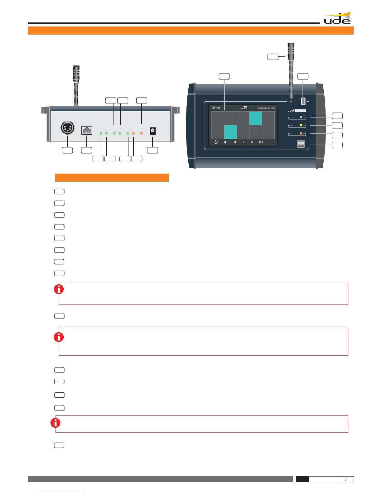
To connect handheld microphone with XLR 5c connector.
USB port
USB 2.0 Type-A.
Frontal LEDs (only informative)
Rear LEDs (only informative)
Power ON, FAULT, MESSAGE.
Device FAIL, LINK OK, LINK FAIL, DATA IN, DATA OUT, AUDIO IN, AUDIO OUT
The user can manage until:
250 PA zones buttons (maximum).
250 extensions in each PA zone button (maximum).
15 group name characters in each PA zone button.
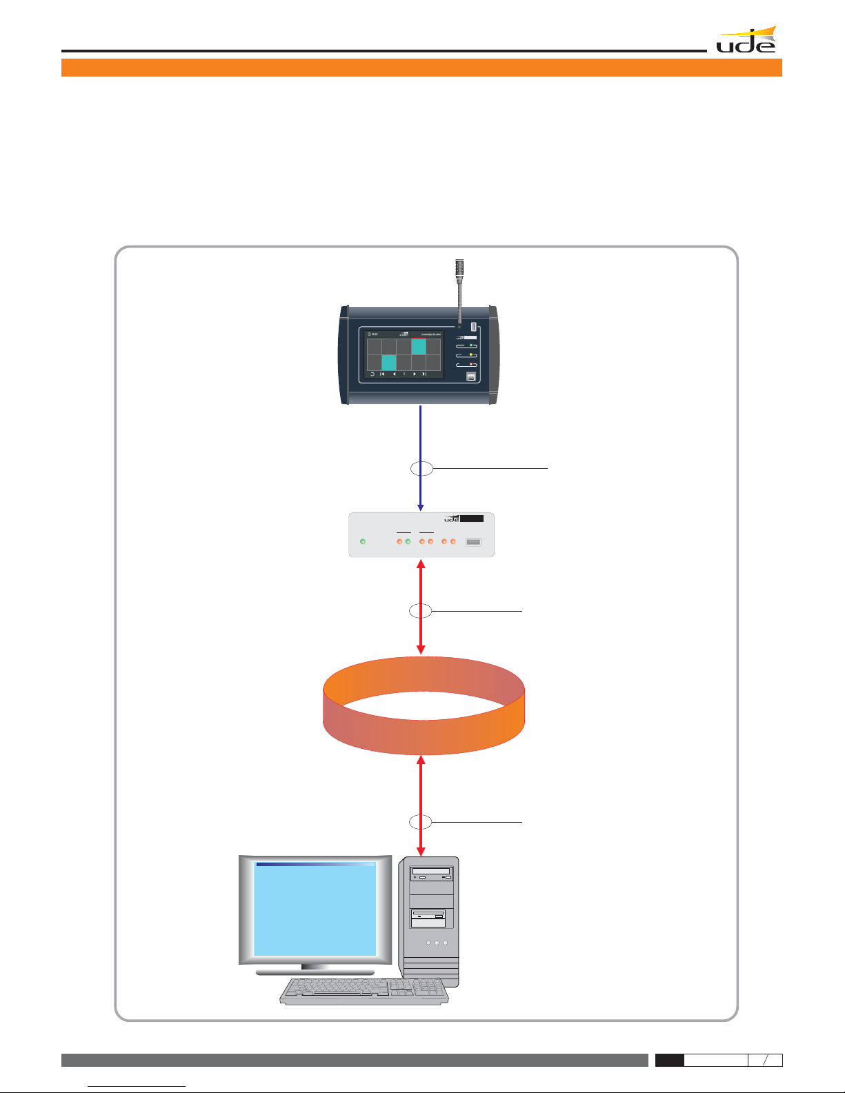
Configuration
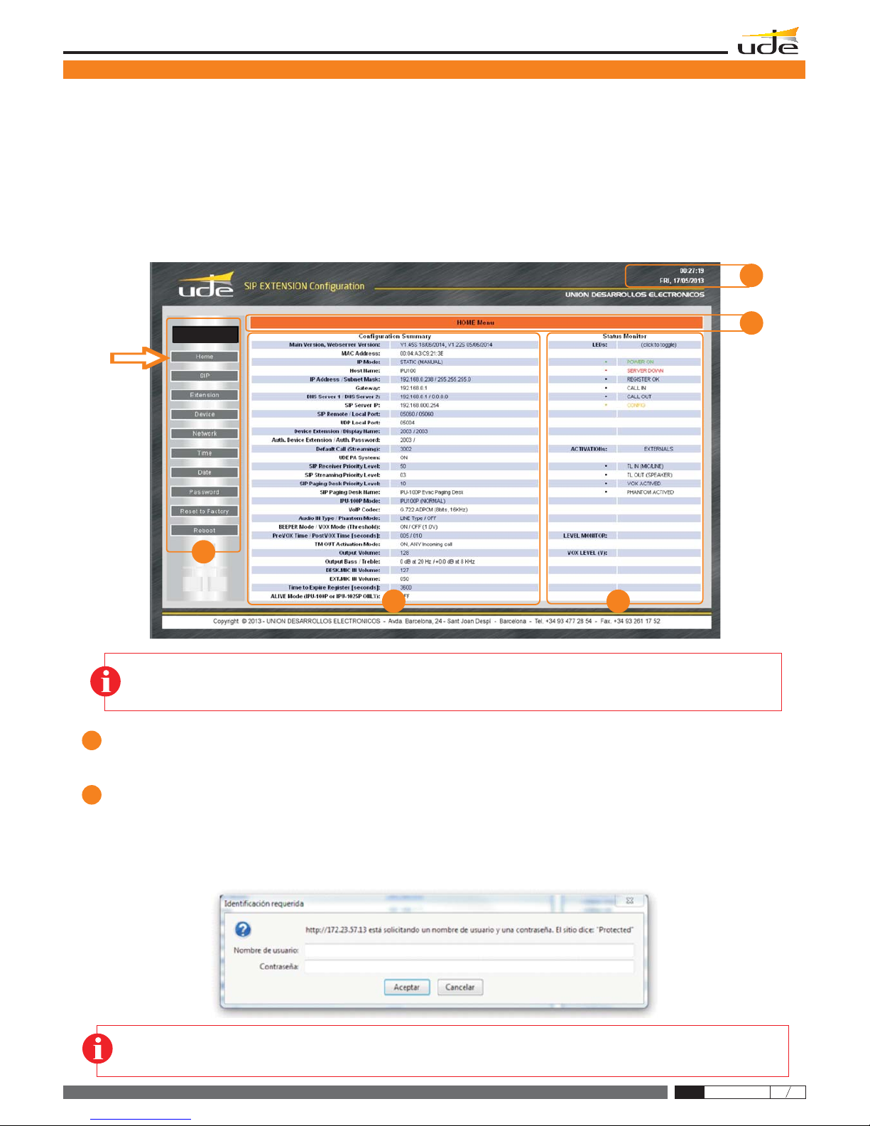
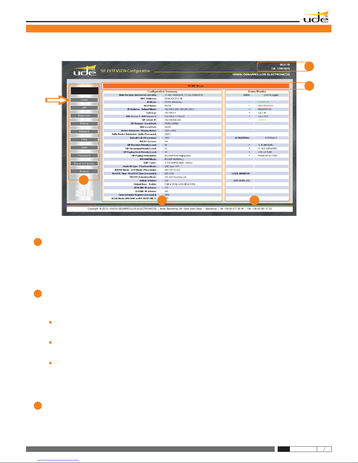
Through a web server interface from the IPU-100 / IPU-1025 to the IPU-100P, it is possible to:
Check the right desk control work.
Password managing.
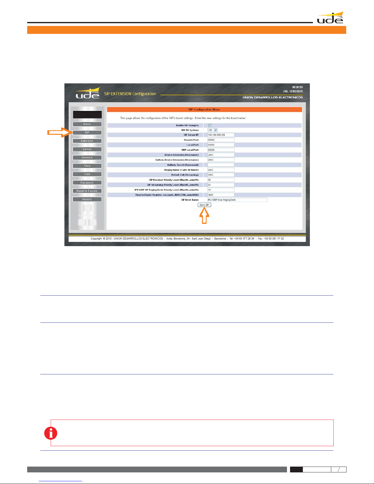
Configuration: SIP parameters / LAN parameters / PA extensions / Hour & date.
Security
8 alphanumeric characters with ASCII between 32 and 127 in IPU-100 or IPU-1025.
Power supply
Consumption
6W max. at 24Vdc.
Operation temperature
-5 a +45ºC (0 a +40ºC, recommended).
Humidity
5% a 95%, without condensation.
Dimensions
318 x 188 x 73 mm.
Weight
1.4 Kg.
Color
Grey (Aluminium).
Main:
Bus AUDIO LINK
AC Adaptor (recommended): 24Vdc (18..30V).
0.9A PPTC internal fuse (resettable).
from IPU-100 or IPU-1025: 24Vdc (18..30V).
Microphone XLR socket
Black gooseneck condenser microphone.
Frequency response: 50Hz-16KHz
Max. Input: 130dB SPL.
Gooseneck microphone
TECHNICAL DATA VALUES
User Manual - IPU-100P
IPU-100P
2
610.462A
Rev. 0
The public address system for IP networks of UNION DESARROLLOS ELECTRONICOS allows the creation of conventional PA
and security systems, allowing interconnecting with IP devices following SIP standard. Unión Desarrollos Electrónicos also offers
the IPU-360 SIP server that will centralize and coordinate all communication of IPpaging elements ensuring maximum functionality
ofall of them, with minimalrisk.
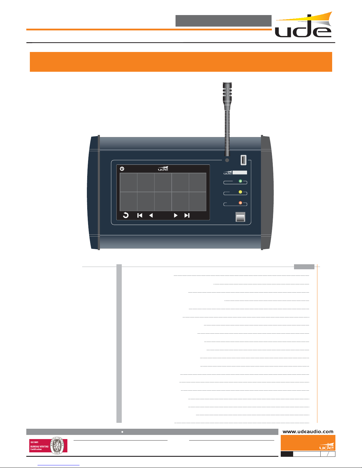
The IPU-100P paging desk allow the user to manage the IP PA system calling individual or groups of zones with user friendly
graphicinterface in a 7” fullcolor touch screen.
The IPU-100P is build with a gooseneck microphone and also with an audio socket for a XLR handheld microphone with remote
switchingcontact.
TheIPU-100Pcharacteristics:
·Manage the zone selection andmake voice calls.
7”TFTfullcolour touch screen
5-pin XLR connector for handheld microphone.
Direct audio & data link with IPU-100 or IPU-1025.
Web server configuration.
100% WIFI compatible (accessories required).
24Vdc power supply connector (for cables greater than 50m).
USB connector for firmware update.
High quality gooseneck microphone
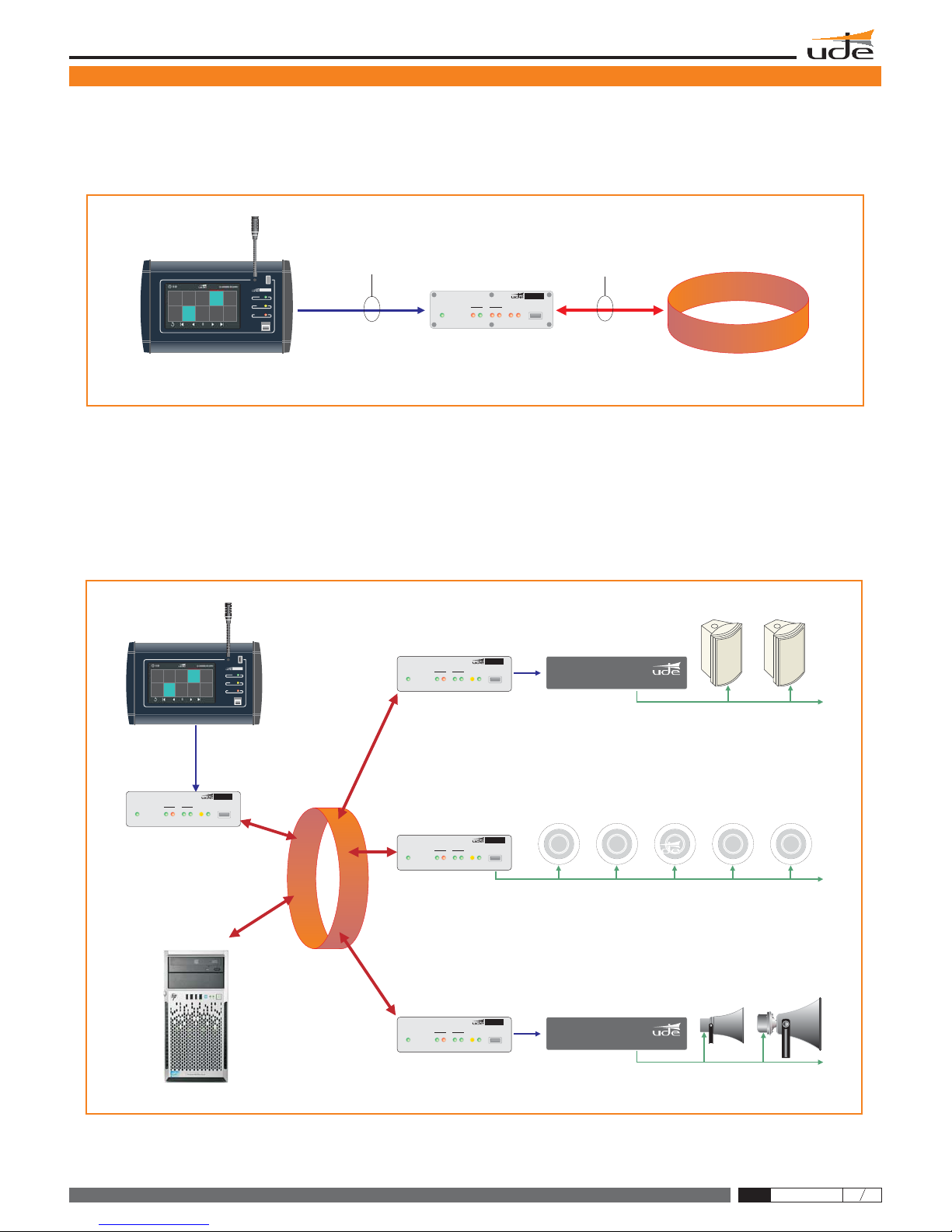
The IPU-100P is the IPsolution for manage PAzones is a highly versatile range of installations: schools, hotels, retail spaces, office
buildings,airports… giving proper solutions from small locationsto a more complex installations.Thegraphic interface gives a great
navigationexperience to the operator, from small places tothe biggest ones.
Technical staff can program until 250 zones in 25 pages with specific name in each zone, configuration process is made with
an easy web interface. IPU-100P shall be installed with IPU-100 or IPU-1025 combination and connected with the audio link
bus, where audio and information travels.
PA zones
28

The figure 1 shows a typical connection between the desk control IPU-100P and the IP network, for that is necessary an
IPU-100or IPU-1025 codifier / decodifier.
Figure 2 provides a configuration example of the PAsystem for IP networks. The encoder / decoder and audio manager, IPU-100 model,
isthe element that allows thedecoding process of audio sent digitally to0dB audio signal.
The IP Paging Desk, model IPU-100P, through an intuitive graphical interface, built-in a 7 " color touch screen, allows the operator to
navigateand select the areas whereto send a message using the microphoneon the same device.
TheSIPserver,IPU-360, which acts as intermediary between allIPdevices over theLAN, coordinating the tasks.
The different elements allow multiple configurations and connections, adding flexibility to combine the wide range of amplifiers, preamps,
poweramps, ..., of UNIÓN DESARROLLOSELECTRÓNICOS.
2.- TYPICAL APPLICATION OF IPU-100P
IPU-100P
Cable UTP Cable UTP
Protocolo
RS-485 + AUDIO Protocolo IP
IPU-100
IPU-1025
IPU-100P
OUT
IN
OK
DEVICE CALL
FAULT CONFIG NET
ACTIVITY
USB
ON
IP
MESSAGE
SPEECH
USB
FAULT
ON
IPU-100P
IPU-1025
IPU-100
IPU-100
IPU-1025
IPU-100
IPU-100P
IPU-360
IP
OUT
IN
OK
DEVICE CALL
FAULT CONFIG NET
ACTIVITY
USB
ON
Engineered and made in E.U.
IPU-1025
OUT
IN
OK
DEVICE CALL
FAULT CONFIG NET
ACTIVITY
USB
ON
Engineered and made in E.U.
IPU-100
OUT
IN
OK
DEVICE CALL
FAULT CONFIG NET
ACTIVITY
USB
ON
Engineered and made in E.U.
IPU-100
OUT
IN
OK
DEVICE CALL
FAULT CONFIG NET
ACTIVITY
USB
ON
Engineered and made in E.U.
IPU-100
MESSAGE
SPEECH
USB
FAULT
ON
IPU-100P
User Manual - IPU-100P 3
610.462A
Rev. 0 28
POWER
AMPLIFIER
POWER
AMPLIFIER

IPU-100P
DC IN
I/O
MIC
IN IN OKOUT OUT FAIL
FAIL
AUDIO DATA LINK
DEVICE
17 16 15
10
12
14 9
11 8
13
REAR
2
3
1FRONT
MESSAGE
SPEECH
USB
FAULT
ON
IPU-100P
4
5
6
7
3.- FRONT VIEW / REAR VIEW
6
5
4
3
2
1
8
7
9
10
12
13
11
14
MICROPHONE. .Gooseneck microphone. Length: 300mm
TOUCHSCREEN. 10 zone touch- buttons per page ready to broadcast public address message.
LED FAULT. LED is disabled.
LED AUDIO IN. LED is disabled.
LED MESSAGE. LED is disabled.
PTT BUTTON. A push-to-talk (PTT) button to start the call when at least one zone is selected.
LED LINK OK. This indicator is activated when exists a right data transmission with IPU-100 or IPU-1025.
LED DATA IN. This indicator shows data modulation sent to IPU-100P.
LED DATA OUT. This indicator shows data modulation sent from IPU-100P .
LED AUDIO OUT. This indicator shows audio modulation from the gooseneck or external microphone.
LED FAIL DEVICE. This indicator is activated when there is a connection problem with IPU-100 or IPU-1025.
LED LINK FAIL. This indicator is activated when exist a wrong data transmission with IPU-100 or IPU-1025.
LED ON. This indicator shows the equipment is properly powered and main application is running.
USB CONNECTOR. The USB connector allows the firmware update.
CONTROLS, CONNECTORS AND INDICATORS
Remember!
If you experience problems with the LED AUDIO OUT, and never turn on, contact the technical staff to guarantee the right operation.
Remember!
If you experience problems with the LINK FAIL, so if it ever turns on sporadically, then it is recommended to reboot the IPU-100P
and IPU-100 or IPU-1025 to solve the communication problem between them. If the problem is no solve it, contact the technical
staff of the installation.
Remember!
If you experience problems with the DEVICE FAIL, so if it ever turns on sporadically, then it is recommended to contact with your
local network administrator (LAN).
User Manual - IPU-100P 4
610.462A
Rev. 0 28

IPU-100P
Conexión fuente de alimentación al pupitre IPU-100P.
Conexión mediante cable UTP al codificador IPU-100 o IPU-1025.
24 VDC
IPU-100/P
IPU-100/P
IPU-100/P
DISTANCIA MENOR DE 50 metros
IPU-100
IPU-1025
IPW-25
IPW-25
100-240 VAC
100-240 VAC
IP
DC IN
LAN
AUDIO LINK +24VDC
TL
TL
MADE IN
SPAIN
IPU-1025
DC IN
DC IN
I/O
I/O
MIC
MIC
IN
IN
IN
IN
OK
OK
OUT
OUT
OUT
OUT
FAIL
FAIL
FAIL
FAIL
AUDIO
AUDIO
DATA
DATA
LINK
LINK
DEVICE
DEVICE
100/230 VAC - 50 Hz
24 VDC / 1,65 A
IPW-25
100/230 VAC - 50 Hz
24 VDC / 1,65 A
IPW-25
The IPU-100P has 2 powering methods available; the power input by the IPW-25 adaptor, is the highest-priority entry and disables the rest. The less
prioritypoweristheaudiolink power supply.
16
17 EXTERNAL MICROPHONE. The XLR 5c socket allow to connect handheld
microphones with push to talk switch, Unión Desarrollos Electrónicos recommends
touse the CM-23 microphone. 5
4
2
1
1
5
4
2
3
3XLR
I/O. This connector allows connection of an IPU-100P or allows the expansion and control, of external devices through the digital bus,
also has a balanced analog audio input and one output that allow the exchange of audio between the IP Paging Desk and the IPU-100
(encoder / decoder). We recommend using UTP wiring to connect both devices. The IPU-100P (IP Paging Desk) can be powered via the
AUDIO LINK when you are less than 50 meters of the IPU-100.
1
2
3
4
5
6
7
8
1
2
3
4
5
6
7
8
BLUEBLUE
BLUE-WHITEBLUE-WHITE
BROWNBROWN
BROWN-WHITEBROWN-WHITE
GREENGREEN
GREEN-WHITEGREEN-WHITE
ORANGE-WHITEORANGE-WHITE ORANGEORANGE
1 1
8 8
EIA/TIA-568B
EIA/TIA-568B
STRAIGHT CABLE
CM-23
15
DC IN PW-25. Jack to connect 24Vdc external power supply. (Model: I ).
3.- FRONT VIEW / REAR VIEW
User Manual - IPU-100P 5
610.462A
Rev. 0 28

IPU-100P
Cable UTP
Cable UTP
Cable UTP
Protocolo
RS-485 + AUDIO
Protocolo IP
Protocolo IP
IPU-100
IPU-1025
ORDENADOR CON
CONEXIÓN A RED
IPU-100P
OUT
IN
OK
DEVICE CALL
FAULT CONFIG NET
ACTIVITY
USB
ON
IPU-100
IP
MESSAGE
SPEECH
USB
FAULT
ON
IPU-100P
EXTENSIONSIP CONFIGURATION(ONLYIPU-100P mode).
The public address zone configuration with an IPU-100P desk control must be done with a IPU-100 codifier. It is not possible to make the
desk control configuration with the touch screen. The extension web server of the IPU-100 menu will allow erasing all IPU-100P zone
buttonsor editing the PAbuttons of the IPU-100Pdesk control.
User Manual - IPU-100P 6
610.462A
Rev. 0
4.- DEVICE CONFIGURATION (WEBSERVER)
28

IPU-100P
4.1 HomePage (HOME).
The HOME page of the IPU-100 WEB application allows everyone access to configuration menus and display the status variables of
theencoder / decoder.
Menus.
Thisarea specifies the different web pages withconfiguration parameters.
ATTENTION: Computer security is a crucial aspect in IP networks. Technical staff is recommended not to store the password default on
computers where you can access unqualified personnel to modify the settings of IP equipment. If you have any doubt, refer to the technical
competence to avoid security problems.
NOTA: UNION DESARROLLOS ELECTRONICOS reserves the right to modify all or part of WEB server design in order to offer a better
product to their customers, which is why we may appear different from pictures provided in this document and results that you can get the
productyou have purchased. Ifyou have any doubtsconsult the technical departmentof UDE.
1
2
2
4
1
5
3
IPU-100P
4. DEVICECONFIGURATION (WEBSERVER).
The IPU-100 configuration is done by accessing to the IP address assigned to the device by the site administrator if you work in
Manualmode assignment (Static Mode), or bythe DHCP server if you workin automatic mode.
Static IP by default is: 192.178.0.210
User Manual - IPU-100P 7
610.462A
Rev. 0
4.- DEVICE CONFIGURATION (WEBSERVER)
28
Listof available Menus.
This area displays the menu selection icons that the user can select for your device configuration. When the user selects a different
menu to the "HOME" (or Main) will be asked to enter a password. If the password is right and match any of the previously stored will
thenopen the desired menu, ifnot the access will be denied.

4
3
5
Summaryof Configuration Parameters.
In this area you can check quickly, what are the basic parameters of the device's. Parameters are displayed relative to the
SoftwareApplication version, the LAN settings (IP, MAC, DNS), the connection parameters to the SIPserver (SIP Server
IP, data ports, SIPExtension number, SIP authentication password, ...), volume values assigned to the audio inputs and
outputs.
StatusMonitor.
LEDsstatus.
Activationsignal status.
Sensorlevel status.
Inthis area you can seethree zones:
Itshows in real time thestatus (on, off,flashing) of allindicators present on the frontpanel.
Showsthe state of the activationsignals of differentbasic functions suchas: VOX activated, MIC activated, etc...
It shows the voltage measurement of the sensors included on the device: 24V Adaptor, 24V Backup Battery, VOX signal
leveldetected, Microphone supply.
Area5: TimeandDate.
IPU-100P
2
4
1
5
3
IPU-100P
User Manual - IPU-100P 8
610.462A
Rev. 0
4.- DEVICE CONFIGURATION (WEBSERVER)
28

IPU-100P
4.2 SIP CONFIGURATION (SIP).
The configuration page allows you to configure SIP parameters to ensure the connection to the installation server IPU-360 (SIP server).
The parameters configured here must be consistent with SIP server parameters of the system.
EnableSIPchanges
UDEPAsystem
SIPServerIPAddress (format: XXX.XXX.XXX.XXX):
168.168.0.254
Incase the checkbox is checked, the SIPparameters are available to be configured.If not the configuration parametersare blocked.
The signaling communication with the server is SIP. Furthermore due to the public address characteristics, the codifiers and
decodersrequires additional information inside the standardized datagram.Choose ON to use theUDE PAsignalinginformation.
Incase of priority or IPU-100Pinstallations,the box must stay inON option. In case of100% SIP standard compliance OFF option.
Defines the IP address where the SIP server host. It is required that the address contains the 12 numbers along with the 3
breakpoints.
Example: SIPServerIP:
¡Attention!
It is MANDATORY for the correct operation of the IP AUDIO devices of UNION DESARROLLOS ELECTRONICOS
that the SIP Server IP address is FIXED address (static type).
The configuration parameters are:
IPU-100P
User Manual - IPU-100P 289
610.462A
Rev. 0
4.- DEVICE CONFIGURATION (WEBSERVER)

Attention!
If you have questions about your authenticated user name or password, contact your Network Administrator or technical staff in
chargeoftheIPU-360configuration(SIP server).
BasicAlphanumeric characters are recommended (standardASCII codes between 32 and 126), excluding special characters or
accentstoavoidtoblocktheaccess in case of any network device or the server does not understand these characters.
Remote Port (format: XXXXX):
05060
Local Port (format: XXXXX):
05060
UDP Remote Port (format: XXXXX):
00000
UDP Local Port (format: XXXXX):
05004
Device extension (username) (from 4 to 8 numbers):
Extensions from 1000 to 1999: Decoders
Extensions from 2000 to 2999: Audio codifiers
Extensions from 3000 to 3999: Music on hold equipments (do not use in other codifiers/decoders configuration)
Extensions from 4000 to 4999: IP desk control (with IPU-100P).
Codifier extension between 2000 and 2499, do not activate the TM OUT in the decoder.
Codifier extension between 2500 and 2999, activate the TM OUT in the decoder.
All extensions between 4000 and 4999 will activate the decoder TM OUT.
1002 2536 1589 4001
Define the management TCP port used by the IPU-360 (SIP server) to communicate with our IPU-100.
The standard default value in the device is 05060, you should keep to ensure compatibility with different SIP servers.
Remember to always use a configuration with 5 digits.
Remote Port:
Define the management TCP port used by the IPU-100 to communicate with the IPU-360 (SIP server).
The standard default value in the device is 05060, you should keep to ensure compatibility with different SIP servers.
Remember to always use a configuration with 5 digits.
Local Port:
Defines the data transmission UDP port (Voice / INFO) used by the IPU-360 (SIP server) to communicate with the IPU-100. The standard
default value is 00000 (automatic mode), you should keep this value to ensure compatibility with different SIP servers.
Remember to always use a configuration with 5 digits.
UDP Remote Port:
Defines the data transmission UDP port (Voice / INFO) used by the IPU-100 to communicate with the IPU-360 (SIP server) on the installation.
The standard default value is 05004 and it is recommended to keep compatibility with different SIP servers.
Remember to always use a configuration with 5 digits.
xample UDP Local Port:
It is the IPU-100 SIP identifier for registering to the IPU-360 (SIP server) to be identified as unique equipment in the SIP net, of the public
address by IP protocol.
In the systems with UDE Audio equipments, the extensions must be contained in a specific rank:
Choose the extension number depending in which application the IPU-100 should work.
Some extensions ranks have additional features:
Local Extension:
Example:
Example:
E:
Example:
Authen. Device Extension (Username): ( ):
12345678
AreaCo_1
Max: 8 alphanumeric characters
Defines the user id in the system when it is working in a secure transmission mode.
: Authen. ID:
This parameter is optional, if not required then leave it blank.
Example
Example:
IPU-100P
User Manual - IPU-100P 10
610.462A
Rev. 0
4.- DEVICE CONFIGURATION (WEBSERVER)
28

Authen. Secret (Password): (Max: 8 alphanumeric characters):
This parameter is required if the parameter "Authenticated ID" is active, otherwise please leave it blank.
DisplayName (Caller ID Name): (format:XXXX):
DefaultCall (Streaming): (format: XXXX):
3400
SIPReceiverPriority Level (Max:01...min:99):(Not use)
SIPStreamingPriority Level (Max:01...min:99):
I
SIP Streaming Priority Level
IPU-100PSIPPaging Desk Priority,
IPU-100PSIPPaging Desk Priority Level(Max:01...min:99):
IPU-100P SIP Paging Desk Priority Level SIP Streaming
Priority
TimetoExpire Register (seconds,MAX:7200...min:0060):
SIPDeskName (Max: 32alphanumeric characters):
HallHotel Las Vegas
Definethe extension to call forractivating thebackground music or for thevoice message broadcast from amicrophone.
Valid values forany extension must be between 3000 and3999.
Example:
DefaultCall (streaming):
f the UDE PAsystem is active and the IPU-100 in codifier mode, a priority can be applied and the IPU-360 will manage. This priority
shouldbe between 01 (max priority)in consequence will cut other emitters and99 (lowest priority).
These characteristics give tools to program de PA system over IP. If you need more information of the max number of priorities,
consultthe IPU-360 datasheet.
The must be configured with audio sources like MP3 players or Microphones like PZ-40 for Music on
holdcalls. It is a differentpriorityfrom the that only concerns deskcontrol microphones.
These characteristics give tools to program de PAsystem over IP, if the IPU-100 is linked with an IPU-100P (desk control), a priority
desk can be applied. This priority must be between 01 (max priority) in consequence will cut other desk control and 99 (lowest
priority).
These characteristics give tools to program de PA system over IP. If you need more information of the max number of priorities,
consultthe IPU-360 datasheet.
The is setting for IPU-100 linked with IPU-100P, is different from the
foraudio sources or microphones.
Registertime for SIPserver update, recommendedtime: 3600 seconds.
TheIPU-100Pdesk control, has a labelidentification name in the mainscreen to identified from otherdesk control in the installation.
SIPDeskName: (20 characters including spaces)
Defines the user password when it is working in a secure transmission mode.
Example: Authen. PASSW.: No utilizar caracteres especiales)zX_0!%¿# (
NOTE:If the IPU-100 is notlinked with an IPU-100P (desk control),this configuration parameter is disabled.
IPU-100P
User Manual - IPU-100P 2811
610.462A
Rev. 0
4.- DEVICE CONFIGURATION (WEBSERVER)

IPU-100P
4.3Extension SIP Configuration (ONLY IPU-100P mode).
The public address zone configuration with an IPU-100P desk control must be done with a IPU-100 codifier. It is not possible to make the
desk control configuration with the touch screen. The extension web server of the IPU-100 menu will allow erasing all IPU-100P zone
buttonsor editing the PAbuttons of the IPU-100Pdesk control.
Thescreen structure of the IPU-100Pis:
Zone extensionZones extensions
Description label Description label
To edit the IPU-100P zones, exists 2 ways:
1. Erasing the whole desk control memory.
2. Editing zones keeping the zones configuration.
The main page have 10 PA buttons and navigation
icons.
Each button/ zone can be edited with a description
text and numbers of zones to call (decoders). The
maximum number of PA zones will be a totally
broadcast message for all the zones configured in
the IPU-360 (SIP server).
Description label.
Zone extension or zones extensions.
IPU-100P Paging Desk
Entrada norte Entrada sur
1
18.12
#001 1003
Entrada norte
#002
Entrada sur
1003
User Manual - IPU-100P 12
610.462A
Rev. 0
4.- DEVICE CONFIGURATION (WEBSERVER)
28

IPU-100P
4.3.1 ERASING & EDITING (Extensions)
Extension main page
Extension NEW DialPLANIn the “ ” page click on:
With this selection the IPU-100P begin the process to erase all the information in memory. The data structure will be the factory
profile.
Erasingprocess page
Depending on the amount of information saved on memory, the erasing process can spend from 10 seconds to 44 minutes to erase all
data.
The IPU-100P screen while the erase process is execute will keep out of work for any paging call. Also a deleting data message will be
printedto give user information.
Zoneedit page
When the erase process has finished, the webpage will be redirected to the zone edit webpage, also the touch screen of the IPU-100P will
work.
Caution! The erasing process is irreversible; in case of error the memory information cannot be recovered.
Deleting data. Please Wait
18.12
User Manual - IPU-100P 13
610.462A
Rev. 0
4.- DEVICE CONFIGURATION (WEBSERVER)
28

IPU-100P
4.3.2 P.A.ZONESEDIT PAGE(Extensions).
Extension EDITDialPlan
Each IPU-100 can be linked only with one IPU-100P. The connection between the codifier and the desk control must be done point-to-
point,and other configuration must berejected.
To access theedit zone page, click on“ ” icon in the leftmenu and click :
If you did the erase memory process, you will be redirected to the PA zones edit page of the IPU-100P.
The zone edit page has two main areas, one is the general navigation and edition of the buttons that already exist in the desk control
(IPU-100P)and another area allows editing onespecific button, adding the labeland the differentextensions that willcall.
User Manual - IPU-100P 14
610.462A
Rev. 0
4.- DEVICE CONFIGURATION (WEBSERVER)
28

IPU-100P
EDITZONE PAGE
First
button
Move one
button back
Move
next button Last
button
Buttonedition indicator Group ID: #001 of 250
Extensions ID: #001 of 250
Button
Extension
Top number
Top number
Groupname
Each IPU-100P button can show a label to give more
information about the zone to call in that button, the label can
havea maximum of 19 alphanumericletters.
Extensionconfiguration in a button.
Example of maxim
numberto edit
012345678
0123456789
Extensioncache:
Add EXTENSION
The extension are saved in a cache memory waiting to be sent to the IPU-100P (the Rank of the extensions is between 1000 and
1999). For example when extension 1300 (typing 300), and clicking “ ” the new number appears in the extension
Validate
SenddataWhenall extensions, labels and buttonsare ready, click on“ ”.This action mustbe done every time onebutton is edited.
Extensionconfiguration
To enter the extensions in a button, the configuration must be done one by one extension, that is enter one extension send the
informationand successively for all the extension tobe in one button.
Furthermore the decoders extension are in the Rank between 1000 and 1999. To make it more simple is precise to type the last 3
digitsof the extension, the firstdigit (number 1) is automatically processed.
IPU-100P buttons navigator. Exist 4 different icons to navigate
along all the buttons of the touchscreen.
1
2
3
4
5
6
7
2
4
1
3
5
6
7
User Manual - IPU-100P 15
610.462A
Rev. 0
4.- DEVICE CONFIGURATION (WEBSERVER)
28

IPU-100P
Buttonconfiguration example
Thisexample contains the configuration of3 IPU-100P buttons, with this characteristics:
BOTTON1
Zone1
1001
Buttonname:
Extensionto call:
BOTTON2
Mainroom
1002,1400
Buttonname:
Extensionto call:
BOTTON3
Yard
1003,1004, 1010
Buttonname:
Extensionto call:
Zone 1
1001
Main room
#002
Yard
IPU-100P Paging Desk
Zone 1
1
00.00
1001
Main room
#002
Yard
#003
#003
ZONE EDIT PAGE
Without any data inside the system, the webpage should look
like:
- Edition of button 1.
- First extension to configure inside the button 1.
User Manual - IPU-100P 16
610.462A
Rev. 0
4.- DEVICE CONFIGURATION (WEBSERVER)
28

IPU-100P
Zone 1
1001
BOTTON 1 EDITION
The parameters to configure for button 1:
Add EXTENSION
Send data.
1.
2.
3.
4
5.
Button 1 label.
Extension to call: 001 (equal to 1001).
Confirm extension with:
. Extension 1001 appears in the extension box.
In button number one has only one extension to call (1001), there is no other extension to configure and configuration must be
uploaded. Click on button:
BOTTON 1 EDITION
Button 1 configuration has been saved and screen shows the new button.
IPU-100P Paging Desk
Zona 1
1
00.00
1001
4
5
3
2
1
001
1001
User Manual - IPU-100P 17
610.462A
Rev. 0
4.- DEVICE CONFIGURATION (WEBSERVER)
28

IPU-100P
Button 2 configuration has been saved and screen shows the new button.
IPU-100P Paging Desk
Zone 1 Main room
1
00.00
1001 #002
Main room
#002
BUTTON 2 EDITION
The parameters to configure for button 2:
Add EXTENSION
2B.
3B. Add EXTENSION
4B.
Send data.
1.
2.
3.
4
5.
Button 2 label.
Extension to call: 002 (equal to 1002).
Confirm extension with:
. Extension 1002 appears in the extension box.
Type the second extension to call in button 2, this is extension 400 (equal to 1400).
Confirm extension with:
Extension 1400 appears in the extension box.
In button number two has only two extensions to call (1002, 1400), there is no other extension to configure and configuration must
be uploaded. Click on button:
BOTTON 2 EDITION
44B
5
3 3B
2B2
1
002
Comedor
1002, 1400
User Manual - IPU-100P 18
610.462A
Rev. 0
4.- DEVICE CONFIGURATION (WEBSERVER)
28

IPU-100P
Button 3 configuration has been saved and screen shows the new button.
IPU-100P Paging Desk
Zone 1 Main room Yard
1
00.00
1001 #002 #003
BUTTON 3 EDITION
The parameters to configure for button 3:
Add EXTENSION
2B.
3B. Add EXTENSION
4B.
2C.
3C. Add EXTENSION
4C.
5.
Send data.
1.
2.
3.
4
Button 3 label.
Extension to call: 003 (equal to 1003).
Confirm extension with:
. Extension 1003 appears in the extension box.
Type the second extension to call in button 3, this is extension 004 (equal to 1004).
Confirm extension with:
Extension 1004 appears in the extension box.
Type the second extension to call in button 3, this is extension 010 (equal to 1010).
Confirm extension with:
Extension 1010 appears in the extension box.
In button number three has three extensions to call (1003, 1004 and 1010), there is no other extension to configure and
configuration must be uploaded. Click on button:
Yard
#003
BOTTON 3 EDITION
44B4C
5
3 3B 3C
2C2B2
1
003
Zona alta
1003, 1004, 1010
User Manual - IPU-100P 19
610.462A
Rev. 0
4.- DEVICE CONFIGURATION (WEBSERVER)
28

IPU-100P
4.4 DEVICE CONFIGURATION. (Device).
This section allows you to configure the analog parameters and modes of the device.
IPU-100 Mode.
IPU-100P (Normal).
To set the mode of the IPU-100 between 3 options:
The IPU-100 will act as an audio emitter point (VOICE mode) being synchronized with the IP Paging Desk connected to the
AUDIO LINK.
Attention! Do not use the IPU-100P Mode when no IP Paging Desk is connected to the AUDIO LINK
terminal as it can lock the IPU-100 temporarily until you perform a reboot of the device.
VoIP Codec.
G.711 (u-Law).
G.711 (a-Law).
G.722(ADPCM).
PCM.
Allows selection of the codec to be used to encode both outgoing and incoming calls when the audio source is a microphone.
The options are as follows:
8 bits logarithmic compression and 8KHz sampling frequency. Quality: Low (As Factory Default).
8 bits logarithmic compression and 8KHz sampling frequency. Quality: Low.
8 bits Adaptive Linear Compression and 16KHz sampling frequency. Quality: Medium.
16 bits without compression and 8KHz sampling frequency. Quality: Good.
PCM. 16 bits without compression and 16KHz sampling frequency. Quality: Very Good.
User Manual - IPU-100P 20
610.462A
Rev. 0
4.- DEVICE CONFIGURATION (WEBSERVER)
28
Other manuals for IPU-100P
1
Table of contents
Other Ude Microphone manuals