4. Operation - How to get started
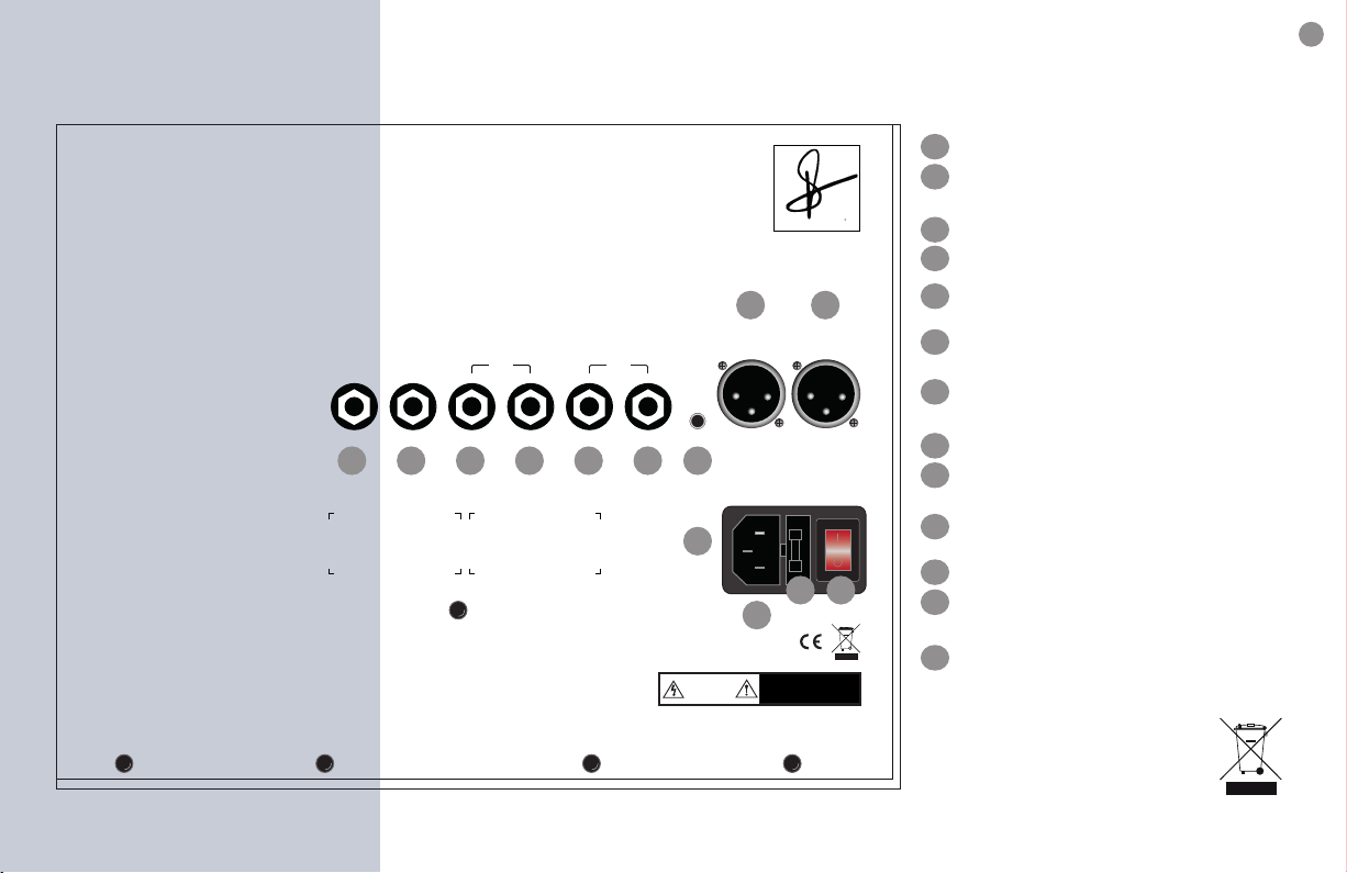
4.1 Above All - Check your local mains!
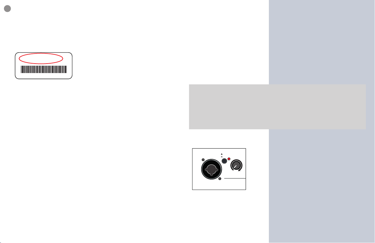
Before connecting to mains, please ensure that your local mains
voltage is suitable to properly operate
the device (e.g. 230V for the EU, 120V for
the US). The relevant specs and safety
symbols are printed on the back-side of
the unit. If you have any doubt, do not
connect the device to mains and consult
a local specialist to verify and assist you.
4.1a Cable up properly - cable clutter
We strongly recommend to solely use proper cable from reputa-
ble cable manufacturers and equivalent connectors. Not only the
sound will clearly benet but trouble shooting will become easier
- any mechanical connection is a potential source of error.
You may need:
-> mono (TS = tip, sleeve), 6.3mm (1/4 inch) jack to jack cables for
your instrument and all line level connections (line out, eect).
-> stereo (TRS = tip, ring, sleeve), 6.3mm (1/4 inch) jack to jack cable
for footswitch and headphone.
-> stereo (TRS = tip, ring, sleeve), 3.5mm (1/8 inch) jack to jack/RCA
cable to connect your playback device to aux in.
-> XLR, 3 pin (1 = ground, 2 = plus, 3 = minus), male - female cable
for microphone.
Connect all cables according to your application before conside-
ring to switch the device on.
Make sure all gains, levels and the master control are in zero- (left
stop) and the tone controls in center-position. You may now switch
the device on. The power switch on the backside is illuminating in
red. The green power control LED on the top will indicate readi-
ness for operation.
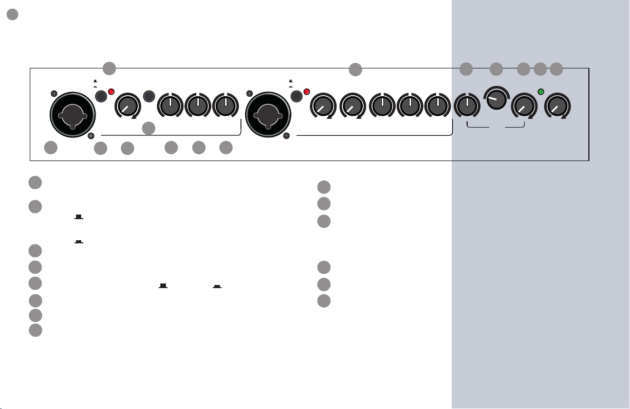
4.2 Gain Structure - Level Adjustment
Note:
A little care should be taken to set the signal level ratios conscious-
ly and correctly. The DaCapo is not simply a box with a speaker, it is
a pretty complex arrangement of signal processing stages that all
interact and need to be in peace with each other for best perfor-
mance - the goal surely is: open, real and most of all undistorted
sound reproduction.
Setting levels correctly means putting signal levels neither too
high nor too low - just at best for the circuit stage within the signal
path thus all circuits are ideally addressed
and none is overloaded or distorted. We
have carefully designed the circuits to
make this possible but sound sources dier
(e.g. pickups, they are matter of individual
preference) and gains, EQs and levels allow
manual intervetion.
In practice: First ensure, that master level control is zeroed (left-
stop). Thus when setting the sound level (gain), the signal can not
reach the loudspeaker to generate unexpected noise. Make your
choice of preamp stage making use of line-/mic-switches according
gaininput 1
clip
channel 1
line
mic
Model: DaCapo75
230V AV 50-60 Hz 220W
Fuse: 1A slow
8