manuals.online logo
Brands
  1. Home
  2. •
  3. Brands
  4. •
  5. UDOR
  6. •
  7. Water Pump
  8. •
  9. UDOR KAPPA-30 User manual

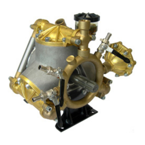
UDOR KAPPA-30 User manual

KAPPA-30& KAPPA-4Omedium pres-
sure,2-cylinderdiaphragmpumpsare
excel-
lentchoicesforvarioushorticulfure,agriculturaf
lawn care,pestcontrolandfurf sprayingapplica-
tions. They arealsoeffectivelyusedin other ap-
plicationssuchasaircraftde-icing,
hydrostatictest-
ing and cleaning.
KAPPA-30& KAPPA-40pumps are constructed
of anodizedaluminum with anodizedaluminum
and stainlesssteelliquid handling parts. Built-in
pulsation dampene4,control valve and pressure
gaugearestandardonallmodels.
Drive optionsinclude:
5027.75 5HP GearReduction
7702.0L 'J.-3
f8",6-spline
malePTO
shaf! base,bolts& safetyshield.
7751,.A1, L" solidkeyedshaft,
base& bolts.
7752.42 1-318"
6-spline
femalePTOadapter& bolts,
lorque arm,chq14s
_&
sq{ety
qhiel4j
For applications not listed"pleaseconsult UDOR U.S.A.
SPECIFICATIONS
Maximum Flow
KAPPA-30 ..8.5GPM
KAPPA-40 10.5
GPM
Maximum Pressure.... 560
PSI
MaximumRPM.......... 540
RPM
MaximumTemperature
............... ..................140'F
Inlet
Port
-
HoseBarb.......... .............1-"
Outlet
Ports
-HoseBarb
(Ball
ValveControlled)................
. ......'l'
12"
(2)
Bypass-HoseBarb.......... ............31
4'
Dimensions................. .................L-10.6"
xW-1'0.9"xH-12.9"
Weight...... 28lbs.
^. -t
Diaphragm Material
Standard DESMOPAN
Optional... ..BUNA-N
NOTE - Protectpumps from freezing. If freezingcondifionsexis! flush pump andsystem
with
a50/50 mixture of anti-freeze
andwater.
UDOR U.S.A.,
INC.
500
Apollo Drive
Lino Lakes,MN 55014
TEL.(612)78s-0666
FAX.
(800)732-2670
Revised4-15-98
CAREFULLY
READAND FOLLOWTHESE
INSTRUCTIONS
BEFORE
OPERATING
YOUR UDOR PUMP. FAILURETO FOL.
LOW THESEINSTRUCTIONS
MAY DAMAGE PUMP AND VOID
WARRANTY.
NOTE
TO PROTECTAGAINST SERIOUS
INIURY NEVER
SPRAY
FLAMMABLE LIQUIDS,ORFLUSHPUMPWITH FLAMMABLE LIQUIDS!
THIS WILL VOID ANY AND ALL WARRANTIES.
UDOR U.S.A.,
tNC.
500Apollo Drive
LinoLakes,MN 55014
TEL.(651)
785-0666
FAX.
(800)
732-2670
1. HOWTHEPUMPWORKS
(The
diaphragm
iswhat
separates
the
pump
oillrom
thespray
material.)
Each
piston
DOWNSTROKElowersthe
piston-attached
diaphragm,
drawingspray
materialinto
pump
head.As
pistonpasses
belowcylindersleevesideopenings,oil
is
pulled
into
lower
diaphragm
cavity.
During
each
piston
UPSTROKEthecushionofoilbetween
thepiston
andthediaphragm
hydraulically
pushes
and
cushions
the
diaphragmasthe
piston
topsout. Thisdischargesthe
fluidinthe
pump
head.
Thelowerdiaphragmcavity
oil
cushionalso
lubricates
thediaphragmand
piston
ensuringminimal
mechanicalwear.
REMEMBERlowoil
level
causesexcessive
mechanicalwearondiaphragmsand
internal
components.
Thetransparentoilsight
glass
makesoilcheckseasy.Keepfilledtomark
onsight
glass.
BEFORE
OPERATINGSYSTEM
OpenSuction
Valve
andchecktightnessofsuction
lines,fittingsand
filter.
DONOTRUNPUMPWITHASTARVEP
SUCTION
Thediaphragm
pump
willnotsufferif rundrydueto an empty
tank. However,a "starved"
suctiondue
to a
cloggedstrainerora closedsuction
valvewill
cause
premature
failureofthe
pump
diaphragms.
NOTE:Only
use
filter
screens
that
arebetween
10&20mesh.Never
useafinefilterscreen
with
a diaphragm
pump.
SUCTION VALVE (To
preventpumpdamage,shut down systembeforeclosingsuctionvalve.)
Thisvalveis inthesystem
to close
offtankflow
foremergencysystem
repairor if strainer
screen
requires
unexpectedcleaningafteratankrefill.
(Strainer
screenshould
becleaned
just
before
eachtank
refill.)
MAINTAINPROPER
OIL
LEVEL
The
crankcaseoil
plays
a dual
role.ltlubricatesallmoving
parts
and
ishydraulicallyfunctional
inthe
pumping
capacity.Oilsupports
thediaphragmduringeach
pressure
stroke.
ltisimportanttomaintaintherecommended
oil
level,
markedontheoilsight
glass.
DONOT
OVERSPEED
PUMP
UDORdiaphragm
pumps
aredesigned
tooperateatorbelowaspecific
speed.Overspeeding
willcause
valves
anddiaphragms
toprematurely
failandcouldcauseother
internaldamage.Refertothe
performance
chart
of
your
specific
pump
formaximumoperatingspeed.
PULSATIONDAMPENERINTRODUCTION
It isthe nature
of diaphragm
pumps
to havesome
pulsation.
Thisis caused
by suddenchanges
in piston
direction.Thepulsation
dampener
has
one
functioninthepumping
system,
reduce
pulsation
by providing
a
cushionof airto bumpagainst.The UDOR
pulsation
dampenerusesa rubberbladder
to separate
the air
cushion
fromthe
solutionbeing
pumped.
PULSATIONDAMPENERSETTING
Thebasicruleistofillthe
pulsation
dampenerto
twenty
percent(20%)
ofthesystem
working
pressure.
If
you
haveyoursprayingpressuresetatl00psi,thesettingforthepulsationdampenershouldbe20psi.
Alwaysshut
down
the
pump
beforeadding
airtothe
pulsation
dampenerorchecking
its
pressure.
Airsupplycanbe
froma
compressororamanualtype
pump.
The
domecontaining
airissmall.
Take
care
toapplythe
pressuregauge
evenlyon
the
air
valveto
prevent
airfromleakingoutofthe
pulsation
dampener.
ltisnot
uncommon
tolose5-
10
psi
when
checking
pulsation
dampener
pressure.
NOTE:2-cylinderdiaphragm
pumps
may
requiremoreair
Ihan2O/"ofoperating
pressure.
20
psi
istheminimum
pulsation
dampener
pressure.
DONOTRUN
PUMP
WITHLESSTHAN20PSIINTHEPULSATIONDAMPENER
2.
3.
4.
5.
6.
7,
8.
Revised 7-1,-97
Establishing
andfollowing amaintenance
addgreatlyto thelongevity of your pump schedule
is agoodinvestment. It will
andyour sprayer.
UDOR DIAPHRAGM PUMPMAINTENANCE PROCEDURE
STEPNO. 2
STEPNO.1 'AFTER EACH USE' flush pump with cleanwater. Most diaphragm " attacks"
occurwhen chemicalsare
left sitting in thepump. Thesefew minutes of clean-
ing arewell spent,extendingdiaphragmlife andminimizing chemical
buildup
throughout thesystem
'AFTER EVERY500
HOURSOFUSEORAT SEASON'S
END'(whichever
comesfirst). Installanew setof diaphragms.Inspectcheck
valves
for spring
fatigueand seatwear. Changeoil usingUDOR LUBE or a non-detergent
40
weight oil: hand rotateshaftwhile filling. Thisevacuates
most unwanted air
pockets. Run pump five minutesunder "rro-load" conditions. This evacuates
remainingairpockets
from diaphragmcavity.Recheckoil level.
STEPNO. 3 'WINTER STORAGE" PerformStepL (above),
theruwith tank empty and
suctionanddischargevalves
"opetr", run pump one
minute toensure
complete
drainage
ofpumpheadsandlines.Recirculateantifreezeand
leavein system
to
completewinterizing procedure.
NOTE: Allow antifreezetoreplace
anypossible
waterinhoses
and
booms.
If a
handgun
isin thesystem,
run antifreezethroughthehoseandhandguninto tanklid open-
ingtoclear
and/ordilutewater. (Depending
onthelengthofhose,morethanone
gallonof antifreezemayberequiredto protect
thesystem
from freezing).
NOTE
TO PROTECTAGAINST SERIOUS
INIURY NEVERSPRAY
FLAMMABLE LIQUIDS,ORFLUSHPUMPWITH FLAMMABLE LIQUIDS!
THIS WILL VOID ANY AND ALL WARRANTIES.
UDOR U.S.A.,
INC.
500
Apollo Drive
Lino Lakes,MN 55014
TEL.
(651)
785-0666
FAX.
(S00)
732-2670
Revised5-1.-99
UDOR diaphragmand plunger pumps "pu*p volume" not pres-
sure. Thepressureis determinedby adjustingtherelief valveand se-
NOTE
TO PROTECTAGAINST SERIOUS
INIURY NEVERSPRAY
FLAMMABLE LIQUIDS,ORFLUSH
PUMPWITH FLAMMABLE LIQUIDS!
THIS WILL VOID ANY AND ALL WARRANTIES.
UDOR U.S.A.,
INC.
500
Apollo Drive
Lino Lakes,MN 55014
TEL.
(651)
785-0666
FAX.
(800)732-2670
lecting proper orifice sizeof spraynozzles.
PROBLEM CAUSE REMEDY
.NO PRESSURE
.VERY LITTLE PRESSURE
.PRESSURE
DROPSBELOW
WORKING RANGE WHEN
RELIEFVALVEISOPEN
TOBOOM ORGUN
Plugged strainerx restricting flow.
Suction hoseobstruction.
Collapsed suction hoseinside or
outside tank restricting flow.
Pump drawing air through suction
line hoses or fittings.
Pressure relief valve stuck or worn
Excessive tank foam due to low
tank volume.
Nozzle volume is greater than
pump capacity.
One or more check valves seating
improperly.
1)
?\
3)
4)
5)
6)
/)
8)
. Clean screen.
. Clear obstruction.
o Replacecollapsedhose.
. Examine hoses and fittings, ensure
air tight fit and no leaks.
. Repair or replace relief valve.
. Refill tank
a. Check relief valve adjustment.
b. Reduce nozzle orifice size or
number of nozzles used.
. Clean or replace check valves.
.PRESSURE
GAUGE
FLUCTUATESWILDLY
oEXCESSIVE
PULSATION
1) Pulsationdampenerpressure
toolow or toohigh
2)Pumpdrawingair through
suction
line hosesor fittings.
3) Pluggedstrainer*
restrictingflow.
4) Air not entirelyevacuated
from
pump cavity.
. Adjust pulsation dampener pressure
(Referto pulsation dampener setting
orrPump OperatiOns Sheet.)
. Examine hoses and fittings, ensure
air tight fit and no leaks.
. Clean screen.
. Run pump with an open discharge
to totally evacuate air.
PUMPDOESNOT
DRAW WATER 1) Pump drawing air through suction
line hoses
or fittings.
2) Pluggedstrainerrestrictingflow.
3) Oneor morecheckvalvesseating
improperly.
r Examine hoses and fittingt ensure
air tight fit and no leaks.
. Clean screen.
. Clean or replace check valves.
PUMPOIL HAS MILKY COLOR
OROIL PLUGPOPSOUT. 1) One or more diaphragms have
ruptured . Replace diaphragms.
*NOTE: Only usefilter screens
that arebetween10& 20mesh. Never usea fine filter screen
with a dia-
phragm pump.
Revised
7-1-97
KAPPA.3O/4o
IEx lodedView ram
and
PartsList
Dia
KAPPA-3Oi4O
PUMPS
Require2O
oz.
UDOR LUBE,
or SAE40W
Non-detergentMotorOil
2602
567
240
794
L299
I 8117
483
1389
357
1038
172'J.
1300 Pq1.!
FORKAPPA-4o/TS
ONLY
FORKAPPA-sO
ONLY
hwa FORKAPPA-3oONLY
m
OTY REF# PART# DESCRIPTION QTY
4
+++17
20
21.
IJJ
155
***163
240
33/
**365
483
484
**498
567
634
"*"635
698
794
803
831
1038
1,072
1126
7299
*1300
0001.06
0002.72
0002.70
0002.71,
0006.02
0007.01
0007.19
0102.04
0202.18
0202.52
0206.08
0206.09
0206.25
0208.34
0209.40
0209.4'1,
021.4.0r
0301.14
0301.30
0302.50
0604.18
0605.09
0608.16
0903.13
0903.r4
1376
*1381
1382
1389
1570
**1578
1702
1727
1795
"*1797
1964
**r967
2045
2051,
21,47
2257
2262
2268
2269
2602
"8117
1101.16
1101..27
11.01..29
11,01,.4r
7205.07
1205.78
6006.01
6017.06
6015.21
6015.23
Retaining Ring
KA PPA 40
/ 50trankshaf t (T.S.
)
KAPPA-30 Crarkshaft
KAPPA-40 / 50 Crankshaft
Bearing
Seal
Seal
Diaphraem BoIt
Intei Hoie Barb (KAPPA-3O/40)
KAPPA-SO Inlet Hose Barb
KAPPA-4O Piston Sleeve
KAPPA-3O Piston Sleeve
KAPPA-SO Piston Sleeve
Accumulator Head
Pump Bodv (KAPPA-30/40/50)
pumb
sodi
it.s.r
Ball Bearink'
Retainer Wisher
Washer
Spacer
Suction Nut
Gasket
Air Valve Assembly
Piston Diaphragm (BUNA-N)
Accumulator Diaphragm
O-Ring
O-Rins
O-Ritrf
O-Ring
Piston--
KAPPA-30/40
Piston
-KAPPA-SO
ValveAssembly
HeadAssembly
Piston/RodAssembly- KAPPA-30/40
Piston/RodAssembly- KAPPA-50
Connecfing
RodPin
- KAPPA-30/40
Connecring
RodPin
-KAPPA-50
SnapRing
SnabRinE
CorinectingRod(KAPPA-30
/40
/50)
Plug
Oil Plus
HeadPIug
Oil SightGlass
Bolt "
PistonDiaphragm (DESMOPAN)
1
4
4
1
z
4
2
2
z
2
2
1
1
1
4
1,
74
2
Revised
4-15-98
OPERATING
INSTRUCTIONS/PARTS
LIST
-6010.24
CONTROL
UNIT
Standard
onKappa
30/40/50/55.and
Tau_35
Vulkollan
Poppet
*PARTS
INCLUDED
INREPAIR
KIT#870I.I0
Repair
Kit
B70t.OZ
isstill
availabte.
The
control
unitfeatures
amanual
dunp valve,
pressure
control
kaob,
glycerin
pressure
qauge,
and
rwo
ball
valve.discharge
;rorts. optional
3/4' Npr outlers
available
. consulr
uDoR u.s.A.
1' Beforeoperatingorre-operatingpump,pushthenunual
dumpvalvelever(Ref.
il21 5)down,sorhe
pump
willstart
at
zero
pressure,
FAILLJRE
TODo so vwu voID ptnfp \\,ARRA|{TY
2' Turn
red
pressure
adjustment
knob
(Ref.H237g)
counter-clockwise
torelieve
spnnc
rension.
NoTE;step
2 applies
onlytoinitial
surt
up,
ancl
is
not
necxsary
indaily
op"r.,,Jo
of pump.
3' Start
unit
and
let
run
until
air
isevacuated
fromsystem,
when
only
liquici
isexpelled
from
rne
Dypass
4' Rerurn
dump
valve
lever
tothe
UP
position,
open
spray
gun
orspray
h:om
andrurn
rhered
pressure
adjustment
knob
clockwise
until
desirecl
oprerating
pr.rrur"
isachieved.
N!TE:
-Protect
pump
from
freezing.
Iffreez:ng
conditions
exist,
flushpump
wirh
a50i
50
rruxfure
ofanti-freeze
and
water.
3@0
As
ofNovember
'l
, 1993
all
6010.24
Control
Units
have
had
the
Ref.No.
1545
1204.19
Steel
Poppet
replaced
with
Ref.
No.
3000
8701.04
Vulkoilan
poppet
asstandard.
NOTE: REPAIR
KtT
NO.
8701.10
NOTTO
BE
USED
WITH
CONTROL
UNIT
6047.06
ni'l
{P
l9l5 /U->.
W)rrt0
(0
358 0202.19
426 0204.40
428 0204.48
459 0205.10
460 0205.1
I
776 0254.04
1034 0604.09
1040 0604.26
1071 0605.05
1124 0608.45
1233 0901.24
1238 0901.47
1275 0902.25
*1304 0903.26
1349 cG-1000
'1368 1101.04
*3000 8701.04
c@
0\i#
l/2"Hose
Barb
Valvc
Body
Main
Body
Valve
Cylinder
Valve
Cylinder
Cam
Bypass
Elbow
H.B,
t.to
Discharge
Barb
Nut9d6
Bypass
BarhNut
Casket
Ball
Valvc
Spring
300#
Spring/Oprional
Dump
Valvc
Lcvcr
Diaphragm
uauge
O-Ring
N
'1370 ll0t.06
1374 1101.12'
*1389 1101.41
14q4 I
203.33
l50t 1203.40
'1545 1204.19
1841 1403.06
1843 1403.07
+
I
s36 1501
.23
2251 1603.02
2379 l80l.l7
2477 1804.67
2419 1804.74
+2630 t810.0
1
7330 0604.29
7700 t603.22
O'Ring
O-Ring
O-Ring
R.V.
Bodv
Adaptcr
l-lrnge
Pop
pe
t
Washc
r
Washc
r
Seat
Pl
ug
Adjustrncnr
Knotr
Bolt
Bolt
S.S,
[]olt
Nut
Pl
ug

This manual suits for next models

1

Other UDOR Water Pump manuals

UDOR ZETA 70 Series User manual

UDOR

UDOR ZETA 70 Series User manual

UDOR DELTA 140 User manual

UDOR

UDOR DELTA 140 User manual

UDOR VY Series User manual

UDOR

UDOR VY Series User manual

UDOR ZETA Series User manual

UDOR

UDOR ZETA Series User manual

Popular Water Pump manuals by other brands

Welch 8905 owner's manual

Welch

Welch 8905 owner's manual

Graco Dyna-Star 77X000 instructions

Graco

Graco Dyna-Star 77X000 instructions

Grundfos SL1 Series instructions

Grundfos

Grundfos SL1 Series instructions

KSB S 100D Booklet

KSB

KSB S 100D Booklet

Lumax LX-1316 quick start guide

Lumax

Lumax LX-1316 quick start guide

Wilo Scot Pump MVI 5 Installation and operating instructions

Wilo

Wilo Scot Pump MVI 5 Installation and operating instructions

Raider RDP-WP28 user manual

Raider

Raider RDP-WP28 user manual

Pentair Pool Products Delta D2CX20-21 Installation & Service Manual with Parts List

Pentair Pool Products

Pentair Pool Products Delta D2CX20-21 Installation & Service Manual with Parts List

Xylem GOULDS 3HM Technical manual

Xylem

Xylem GOULDS 3HM Technical manual

Oase ProMax Garden Classic 4500 operating instructions

Oase

Oase ProMax Garden Classic 4500 operating instructions

Pfeiffer Vacuum TMH 071 P operating instructions

Pfeiffer Vacuum

Pfeiffer Vacuum TMH 071 P operating instructions

Parker PGM 600 Series Service manual

Parker

Parker PGM 600 Series Service manual

Kremlin-Rexson airmix instruction manual

Kremlin-Rexson

Kremlin-Rexson airmix instruction manual

FLORABEST FTP 400 D3 Translation of the original instructions

FLORABEST

FLORABEST FTP 400 D3 Translation of the original instructions

Little Giant 5-MSP Series instruction sheet

Little Giant

Little Giant 5-MSP Series instruction sheet

EUROPRO HYDROPRO 800 Premium user manual

EUROPRO

EUROPRO HYDROPRO 800 Premium user manual

Master cool 90058-AUT operating instructions

Master cool

Master cool 90058-AUT operating instructions

WaterAce WA62UP owner's manual

WaterAce

WaterAce WA62UP owner's manual

manuals.online logo
manuals.online logoBrands
  • About & Mission
  • Contact us
  • Privacy Policy
  • Terms and Conditions

Copyright 2025 Manuals.Online. All Rights Reserved.