UDP Technology IPX3702HD-5314 User manual

IPX3702HD-5314
Installation Guide

INFORMATION TO USER
CAUTION
RISK OF ELECTRIC SHOCK,
DO NOT OPEN
!
CAUTION: TO REDUCE THE RISK OF ELECTRIC SHOCK,
DO NOT REMOVE COVER (OR BACK).
CONTACT QUALIFIED SERVICE PERSONNEL FOR INTERNAL PARTS.
This symbol is intended to alert the user the presence of un-insulated
“dangerous voltage” within the product’s enclosure, which may be sufficient
magnitude to constitute a electric shock risk to persons.
!
This symbol is intended to alert the user the presence of important operating
and maintenance (servicing) instructions within the guide manual.

IPX/IPN Series Installation Guide
01A.01 3
Table of Contents
1. FEATURES ............................................................................................................. 4
2. PACKAGE CONTENTS............................................................................................. 5
3. PART NAMES ........................................................................................................ 6
4. INSTALLATION ...................................................................................................... 7
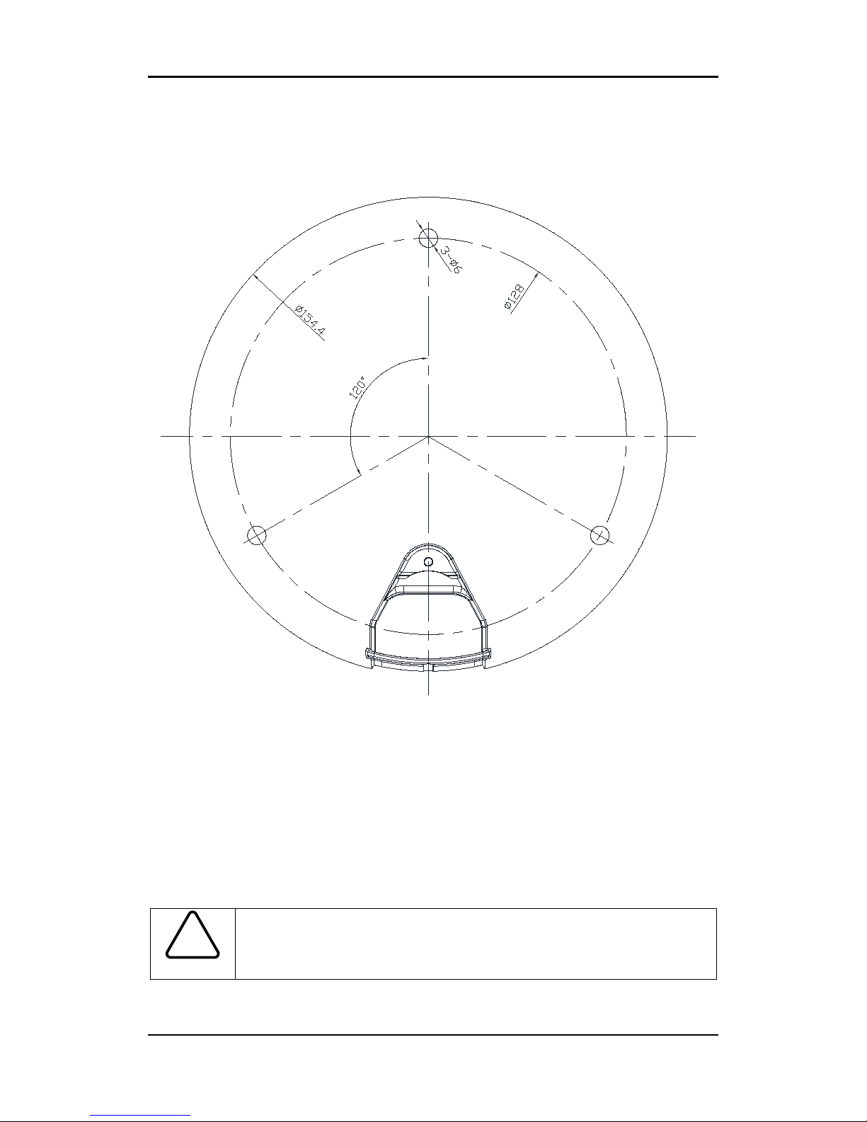
4.1. Installation Template ......................................................................................................... 8
4.2. Setting the Lens Position.................................................................................................... 9
4.3. Setting the Image Attribute ............................................................................................... 9
5. CONNECTIONS.................................................................................................... 10
6. CONFIGURATION ................................................................................................ 12
6.1.Set up network environment ............................................................................................ 12
6.1.1. Generic IP Environment ............................................................................................ 12
6.1.2. Custom IP Environment............................................................................................. 13
6.2. View video on web page .................................................................................................. 14
6.2.1. View video using IPAdmin Tool ................................................................................. 15
6.3. Reset................................................................................................................................. 16
6.4. Factory Default................................................................................................................. 16
APPENDIX (A): SPECIFICATIONS .............................................................................. 17
Summary ................................................................................................................................. 17
Electrical Characteristics ......................................................................................................... 18
Environment Condition ........................................................................................................... 18
Mechanical Condition ............................................................................................................. 18
APPENDIX (B): POWER OVER ETHERNET ................................................................. 19
PoE compatibility .................................................................................................................... 19
Power classification................................................................................................................. 19
APPENDIX (C): DIMENSIONS ................................................................................... 20
APPENDIX (D): HEXADECIMAL-DECIMAL CONVERSION TABLE ................................. 21
REVISION HISTORY ................................................................................................. 22

IPX/IPN Series Installation Guide
01A.01 4
1. FEATURES
Camera
•Full HD outdoor fixed dome IP camera (Vandal proof)
•High quality compression in real time streaming
•1/2.7” High Quality CMOS Image Sensor
•True Day / Night (ICR)
•Remote Zoom/Focus Control(One Click AF)
Streaming
•Dual streaming mode
•De-interlacing on DSP
•Burnt-in text supported
•Unicast/Multicast supported
Video/Audio
•Video compression: H.264/MJPEG, 25/30FPS@1080p(PAL/NTSC)
•Audio compression: G.711(µLaw, aLaw)/PCM
•Analog video out for external monitors
•Video motion detection supported
•Two-way mono audio supported
Network
•RTSP/ HTTP protocol supported
•10/100 Base-T Ethernet
Additional Features
•Micro SD card support
•PoE support
•Built-in Video Content Analysis
•Internal fan/heater
•IP66 certified
•SDK (Software Development Kit) provided

IPX/IPN Series Installation Guide
01A.01 5
2. PACKAGE CONTENTS
Unpack carefully and handle the equipment with care. The packaging contains:
Camera
DC power adaptor
DC jack cable
8-pin and 2-pin terminal block
S-Video jack to 3.5mm plug
Screws and anchors
Side plug
Hex wrench driver
Side cover
RJ45 coupler
Quick installation guide
Installation template
Note
i
The package contents are subject to change without prior notice.

IPX/IPN Series Installation Guide
01A.01 6
3. PART NAMES
①Rest button
The reset button can be used for restarting the device or resetting it to Factory Default.
②Focus buttons
Use the buttons to manually/automatically determine correct focus.
③Zoom In/Out buttons
Use the buttons for camera to cover the wide field of view or to concentrate narrow field of view.
④PAL/NTSC button
Pressing the button cycles through PAL, NTSC, and no video output mode: No video output -> PAL->NTSC
⑤Video stereo jack connector
Connector for 3.5mm video jack plug.
⑥MicroSD
SD card supports up to 32GB
⑦Tilt buttons
Use the buttons to control rotation of the lens in a vertical plane.
⑧Pan buttons
Use the buttons to control rotation of the lens in a horizontal plane.
②
③
⑤
* Models and their appearance are subject to change without any prior notice.
④
⑧
①
Top View
⑦
⑥

IPX/IPN Series Installation Guide
01A.01 7
4. INSTALLATION
1) Place the installation template (paper) that
is included in the package on the desired
installation surface.
2) Drill three holes in correct positions based
on the template paper, and insert anchor
blocks into the holes.
3) When placing
the camera body to the
installation surface,
match three alignment
holes with three anchor blocks.
4) Tighten the surface anchor studs.
5) Connect all the r
equired cables to the
camera.
6)
Adjust the lens position. Detailed
information can be found in
4.2. Setting the
Lens Position.
7) Place the dome cover on the main body of
the camera. Dome cover has three alignment
holes that match camera body’
s alignment
holes.
8) Once properly placed, insert hex screws
into the three holes of the body and tighten
them up with hex wrench driver.
Caution
!
To prevent products from damaging, place the camera on stable and non-vibrat
ing surfaces. If the stability is in doubt, consult with safety personnel for reinfor
cements, and then proceed with the installation.

IPX/IPN Series Installation Guide
01A.01 8
4.1. Installation Template
Caution
!
Installation template image’s size scale in this installation guide is not 1:1.
The correct-size template design paper can be found inside the package separ
ately.

IPX/IPN Series Installation Guide
01A.01 9
4.2. Setting the Lens Position
1) Remove the dome cover to control the positioning buttons, or use web site setup (Setup >
Video & Audio >Repositioning) to adjust the camera.
2) Refer to 3. Part Names for the button locations; to pan, use ‘+’ and ‘–‘pan buttons. To tilt,
use ‘+’ and ‘-‘tilt buttons.
Caution
!
Lifespan of PAN and TILT are approximately good up to 5,000 counts each.
4.3. Setting the Image Attribute
Through the camera’s webpage, users can configure image settings.
The camera image’s brightness, contrast, saturation and sharpness are adjustable through the
image settings. (Setup > Video & Audio > Camera).
Even though the camera can pan 360 degrees,
the recommended “default”
front of the
camera housing is described on a right figure.
Please refer to the diagram below for the
proper camera housing position and the
camera lens:
B. Pan the lens with
pan ‘+’ and ‘-‘ buttons
A. Tilt the lens with
tilt ‘+’ and ‘-‘ buttons
PAN & TILT buttons

IPX/IPN Series Installation Guide
01A.01 10
5. CONNECTIONS
①
Audio input/output
The camera has a mono audio input and a mono audio output. Due to low audio output power,
an amplified speaker is recommended for enhanced sound (Do not connect a headphone or
earphone directly to the camera).
②
Sensor (DI) connection
The camera provides 1 channel D/I. It can be connected to either a voltage type sensor or a
relay type sensor as the following figures. Settings can be done through the camera’s webpage
Input voltage range: 0VDC minimum to 5VDC maximum, Max 50mA
Input voltage threshold: 1.5V
Caution
!
Do not exceed the maximum input voltage or relay rate.
DO DI
1
OutOut
1
VIDEO
C C In
AUDIO
ETHERNET
Mic
Amp Speaker
Out
In
AUDIO

IPX/IPN Series Installation Guide
01A.01 11
③
Alarm (DO) connection
Only the relay type is supported.
Relay Rating: Max 24VDC 50mA
Caution
!
Do not exceed the maximum relay rating.
Caution
!
Must connect GND port which is located end of the DO terminal block side.
④LAN connector
This is a 10/100 Base-T Ethernet cable.
Use RJ45 coupler to extend the cable.
⑤12V DC Power
A 12 DC power connector is required for this device.
12V
Red
Black
DO
COM
Device
Internal
Relay Type
+3.3V
DI
COM
DI
COM
+
-
+
-
Output of
Sensor
Output of
Sensor
Internal
Internal
+
-
Relay Type
Voltage Type

IPX/IPN Series Installation Guide
01A.01 12
6. CONFIGURATION
6.1.Set up network environment
The default IP address of the device is 192.168.XXX.XXX. Users can identify the IP address of the
device from converting the MAC address’s hexadecimal numbers, which is attached to the
device. Be sure that the device and PC are on a same area network before running the
installation.
IP address : 192.168.xxx.xxx
Subnet mask: 255.255.0.0
6.1.1. Generic IP Environment
In case of generic private network environment where IP address 192.168.XXX.XXX are used,
users may view the live streaming images on a web page using the device’s default IP address:
1. Convert the device’s MAC address to the IP address. Refer to the Hexadecimal-Decimal
Conversion Chart at the end of the manual.
(The MAC address of the device is attached on the side or bottom of the device.)
2. Start the Microsoft® Internet Explorer web browser and enter the address of the device.
3. Web streaming and device configurations are supported through ActiveX program. When the
ActiveX installation window appears, authorize and install the ActiveX.
MAC address = 00-13-23-01-14-B1 → IP address = 192.168.20.177
Convert the last two set of hexadecimal numbers to decimal numbers.

IPX/IPN Series Installation Guide
01A.01 13
6.1.2. Custom IP Environment
IPAdminTool is provided with SDK at the following SDK path.
{SDK root}\BIN\TOOLS\AdminTool\
IPAdminTool is a management tool, which automatically scans all of the network products for
users to perform administrative tasks, which includes network configurations, firmware update,
device reboot, and device organizations.
To modify the device’s default IP address for customized network area;
1. Find the device from the IPAdminTool’s list and highlight the device’s name.
2. Right-click the mouse and select “IP Address”; IP Setup window appears.
3. In the IP Setup’s window, information under ‘Local Network information’ displays the
user/PC’s network area information. Those information need to be incorporated to the IP
Address, Subnet Mask, Gateway, and DNS boxes, except the last 2 sets of IP Address, which
are to be the unique numbers for the device. Refer to the image above for the setting
4. Click ‘Setup’ to complete the modification.
PC environment Info
Give new unique IP
address in last two sets

IPX/IPN Series Installation Guide
01A.01 14
6.2. View video on web page
Type the proper IP address to view the live streaming images through a web browser.
The default username and password is root / pass.
1. The browser asks to install the ActiveX. Click Allow.
2. Setup.exe installation link or pop-up window appears, depends on Microsoft® Internet
Explorer version. Proceed with rest of setup installation.

IPX/IPN Series Installation Guide
01A.01 15
Caution
!
Caution
!
3. Follow the instructions of the dialog boxes and complete the installation. Once the
installation is complete, start the web browser again and check if video stream is
displayed in the main view frame.
If “This software requires the Microsoft XML Parser V6 or higher. Please
download MSXML6 from the Microsoft website to continue. Error code: Cannot
create XMLDOMDocument.” message appears, download and
install the
Microsoft Core XML Services (MSXML) 6.0.
6.2.1. View video using IPAdmin Tool
IPAdminTool automatically searches all activated network encoders and IP cameras and shows
the product name, IP address, MAC address and etc. IPAdminTool is provided with SDK at the
following SDK path.
{SDK root}\BIN\TOOLS\AdminTool\
1. From the IPAdminTool’s product list, select the device by highlighting it.
2. Right-click the mouse and select Web view
3. The system’s default web browser opens the device’s address.
Whether directly accessing the streaming video through typing IP address on a
web page or taking steps through IPAdminTool, the ActiveX is needed to be
installed for the Microsoft®
Internet Explorer to have the complete
configuration privileges.

IPX/IPN Series Installation Guide
01A.01 16
6.3. Reset
Refer to 3. Part Names for the reset button location.
Perform the following procedures to reset your device:
1. Push the Reset button and hold for 1~2 seconds. The red led lights up.
2. Wait for the system to reboot.
6.4. Factory Default
Refer to 3. Part Names for the reset button location.
Resetting the device back to the factory default will initialize all parameters including the IP
address back to the factory defaults. To reset back to the factory default;
1. Push reset button and hold for 5 seconds.
2. Release the Reset button when green LED blinks. The red led lights up few seconds later.
3. Wait for the system to reboot.
The factory default settings can be inferred as follows:
IP address: 192.168.xx.yy
Network mask:
255.255.0.0
Gateway:
192.168.0.1
User ID:
root
Password:
pass

IPX/IPN Series Installation Guide
01A.01 17
APPENDIX (A): SPECIFICATIONS
Summary
Camera Module
CMOS
Image Sensor
1/2.7” 1080p CMOS
Effective Pixels
1920x1080
Scanning system
Progressive scanning
ELECTRICAL
Resolution
1920 x 1080
Min.
Illumination
Color: 0.5 lux, F1.2
BW: 0.001 Lux (B/W, Sens-up 32X)
AGC Control
Auto
Lens
Focal Length
3.0 ~ 9.0mm
Aperture Length
Fw1.2 ~ Ft/2.1
Zoom Ratio
3X
Day & Night
Removal IR Cut Filter
Video
Compression Format
H.264, MJPEG Selectable per Stream
Number of Streams
Dual Stream, Configurable
Resolution
1920x1080, 1280x720, 800x450, 480x270, 320x180
Compression FPS
Full-frame@1080p
Motion Detection
Built-in
Burnt-in Text (Digital)
Video stream overlay text
Output
Digital video output
Audio
Input/output
1/1 channel
Compression Format
G.711
Function
Digital Input/output
1/1 channel
RS-485
Not supported
Network
10/100 Base-T
Power over Ethernet
Supported
Protocol
TCP/IP, UDP/IP, HTTP, RTSP, RTCP, RTP/UDP, RTP/TCP,
SNTP, mDNS, UPnP, SMTP, IGMP, DHCP,
DDNS, SSL v2/v3, IEEE 802.1X, SNMP v2/v3
SD Slot
Supported (MicroSD)
※Micro SD Card not included
(Recommend Class 4 and higher for HD recordings)

IPX/IPN Series Installation Guide
01A.01 18
Electrical Characteristics
Power Source
DC 12V, AC24V / PoE IEEE802.3af (Class 0)
Power Consumption
DC12V and AC24V : 1.5A
PoE : 800mA
Video Output
1 Vp-p, 75Ω, Composite
Audio Input
MICin, 0.178Vp-p, 10K Ω
Audio Output
Lineout, 2.26Vp-p, 10K Ω
D/I
Max 50mA@5VDC, TTL level 1.5V threshold
D/O
Max 50mA@24VDC
On-state resistance: 50 Ω (max continuous)
Environment Condition
Operating Temperature
DC12V and AC24V : -20˚C ~ 50˚C (-4˚F ~ 122˚F)
PoE : 0˚C ~ 45˚C (32˚F ~ 113˚F)
Motor Spin: 10˚C ~ 40˚C (50˚F ~ 104˚F)
Operating Humidity
Up to 85% RH
Mechanical Condition
Material
Aluminum Die Casting
Color
Ivory
Dimension
Housing : 154.4(Ø) x 130 (H) mm
Dome: 100(Ф) mm
Weight (Approx.)
1.2kg
PAN/Tilt Lifespan
Approx. 5,000 counts each

IPX/IPN Series Installation Guide
01A.01 19
APPENDIX (B): POWER OVER ETHERNET
The Power over Ethernet (PoE) is designed to extract power from a conventional twisted pair
Category 5 Ethernet cable, conforming to the IEEE 802.3af Power-over-Ethernet (PoE) standard.
IEEE 802.3af allows for two power options for Category 5 cables.
The IEEE 802.3af-2003 standard allows up to 15.4 W power to device. However, 12.95W is the
maximum available power, as some power gets lost in the cable.
PoE has advantages over conventional power in such places where AC powers cannot be
reached or expensive to wire.
Note: For proper activation of 12V PoE, the Category 5 cable must be shorter than 140m and
conform the PoE standard.
PoE compatibility
With non-Power Sourcing Equipment (PSE)
When it is connected with non PSE, the power adaptor should be connected.
With power adaptor
Connecting both PSE and power adaptor does not do any harm to the product, but power
adaptor will be the only power source for the device as it has priority over PSE. In this case,
disconnecting power adaptor while it is operating will cause the device to reboot. And PoE will
be the power source for the device after the reboot.
Power classification
The PoE Power Class supported by the IP device is Class 0.
Class
Usage
Minimum Power Levels
Output at the PSE
Maximum Power Levels at
the Powered Device
0
Default
15.4W
0.44 to 12.95W
Note
i
Unlike the other way, disconnecting PSE or PoE doesn’t reboot the device as
long as a power adaptor is connected.

IPX/IPN Series Installation Guide
01A.01 20
APPENDIX (C): DIMENSIONS
(Unit: mm)
Table of contents
Other UDP Technology IP Camera manuals