MicroLED Li ht Source Ran e
10
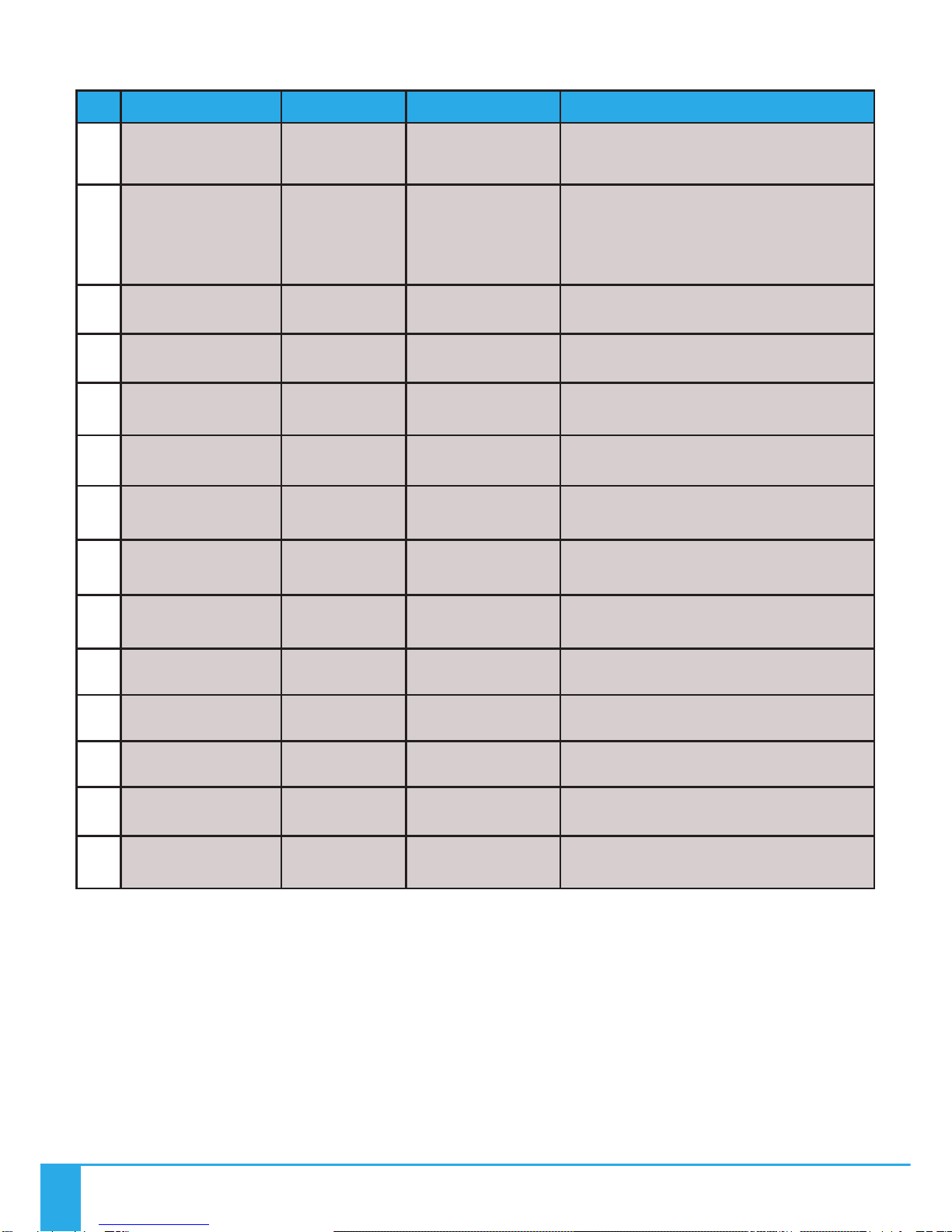
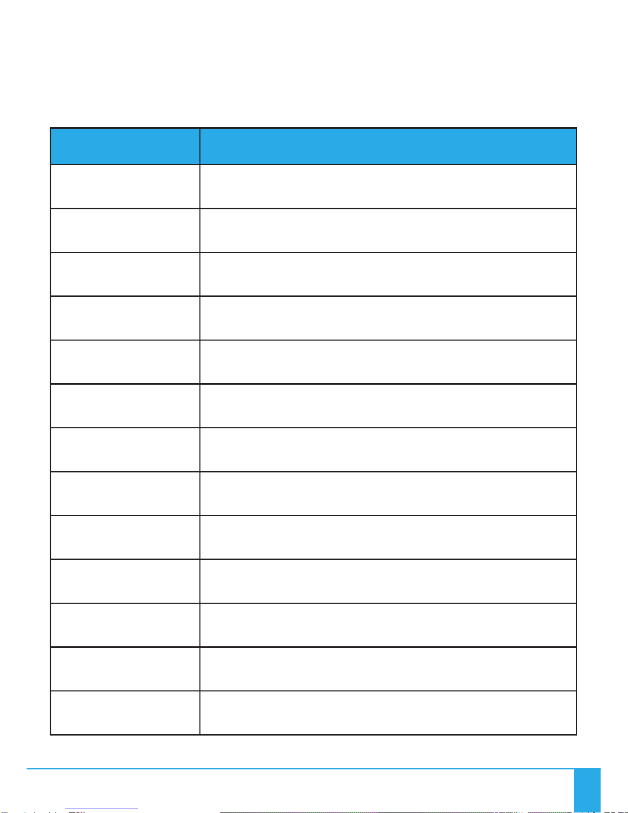
Problem Probable cause(s) Remedy
Unit is dead - LED ower
indicator is not illuminated
Mains supply off Check supply and reinstate
Loose mains plu s Check plu s
PSU failed Replace PSU
Unit is dead - no light out ut but
LED ower indicator is still
illuminated
LED array failure Replace Li ht Source
May have been switched off usin
Remote Controller
Recycle power to Li ht Source or
switch on usin Remote Controller
Remote Controller range reduced
or ersistently freezing
Remote Controller batteries
failin
Replace batteries as per user uide
instructions and carry out matchin
if necessary
Somethin new causin
interference within operatin
ran e
Check for another device
transmittin RF interference
Remote Controller needs resettin
Power the Remote controller down
by removin and reinstallin the
batteries as per User Guide
instructions
Remote Controller failin Replace Remote Controller
Li ht Source Receiver Failin Replace Li ht Source
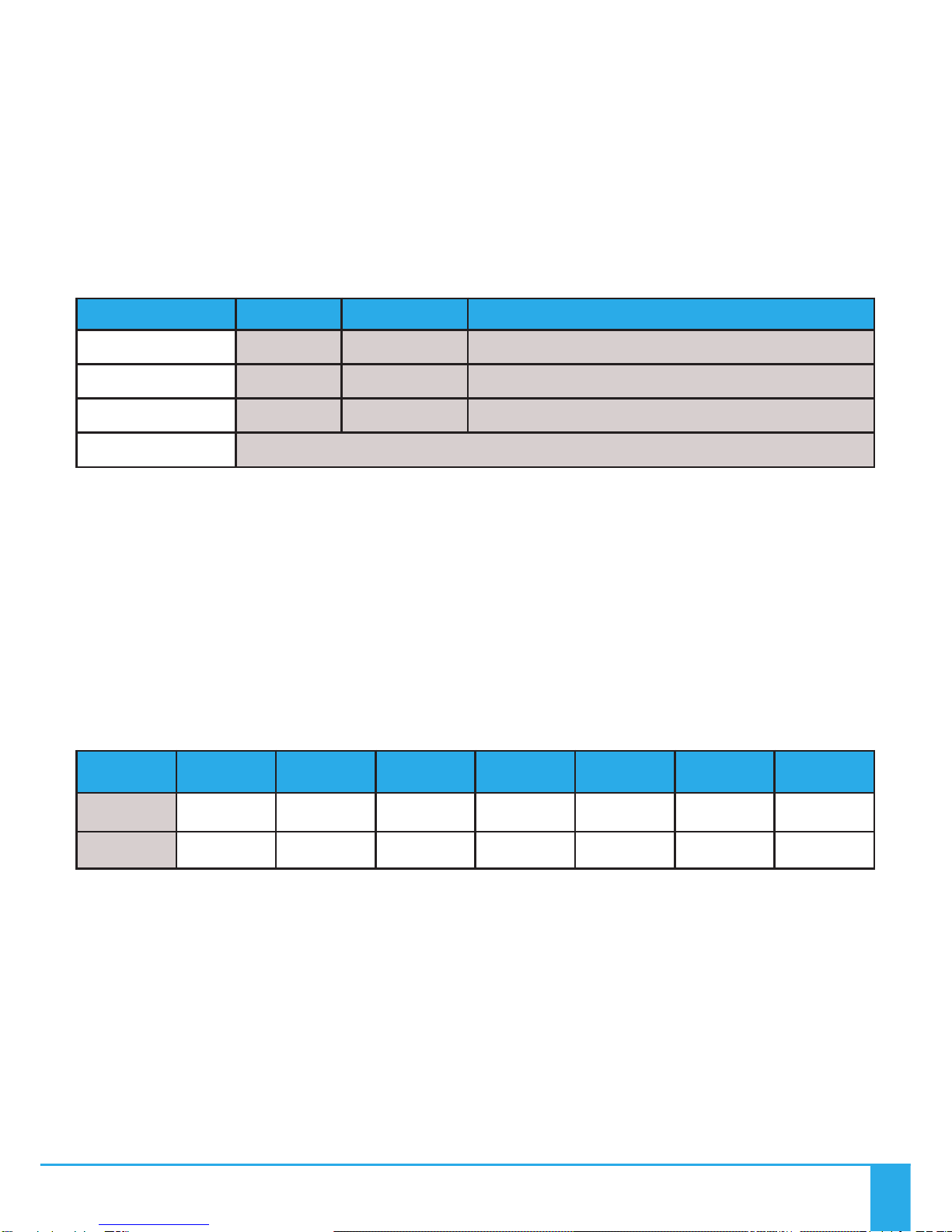
Unit won’t res ond to Remote
Controller
Remote Controller batteries failed Replace batteries and carry out
matchin if necessary
Li ht Source in stand alone mode Recycle power to Li ht Source
Remote Controller needs resettin
Power the Remote Controller down
by removin and reinstallin the
batteries as per User Guide
instructions
Remote Controller not “matched”
to Li ht Source
Carry out “matchin ” procedure as
detailed in REMOTE OPERATION
Remote Controller failed Replace Remote Controller
Li ht Source Receiver Failed Replace Li ht Source
Poor Light out ut on fibre
Unit needs cleanin
Carefully clean LED lens with dry
cloth
Clean Fibre common end
Fibre port connector not plu ed
in correctly
Ensure plu ed in correctly and
secured with lockin screw
In Stand Alone Mode - Stationery
on one colour Lower Button has been pressed Press Lower button once
LED Driver has failed Replace Li ht Source
In Stand Alone Mode - Colour
cycle cannot be sto ed LED Driver has failed Replace Li ht Source
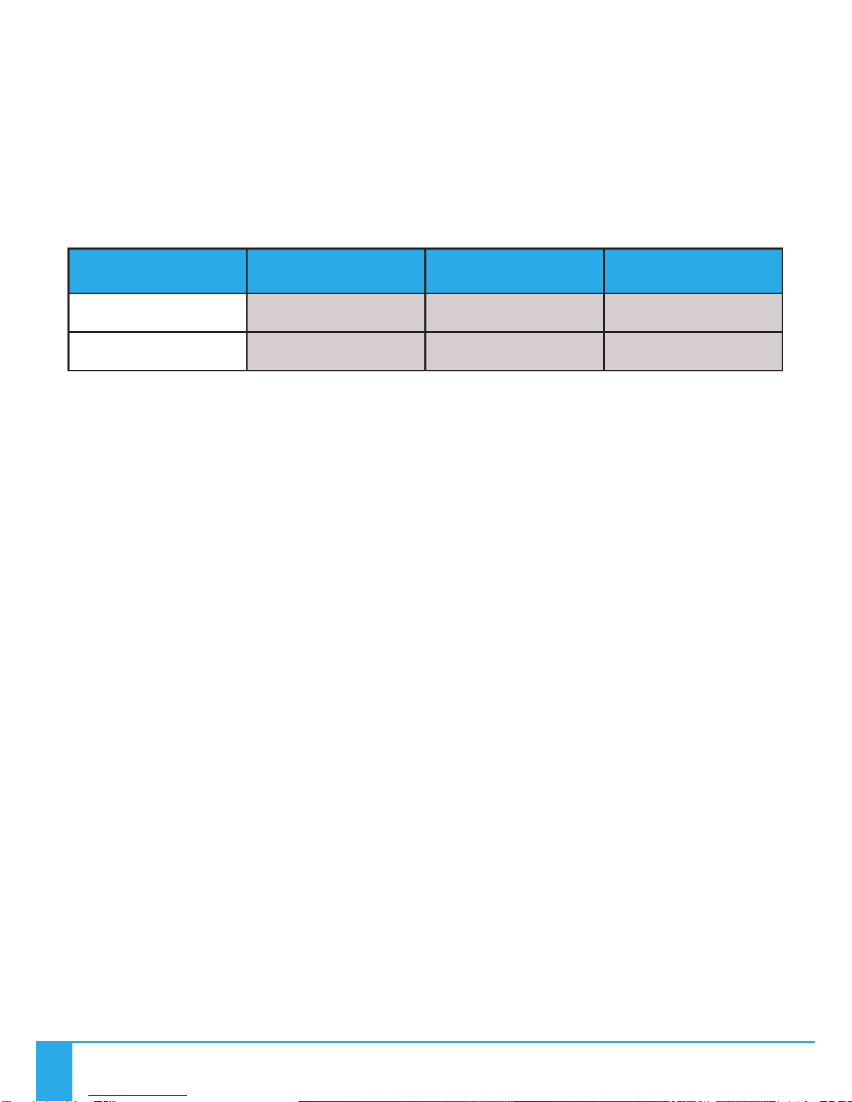
TECHNICAL SPECIFICATIONS
Please complete troubleshootin procedures before returnin the unit to us.