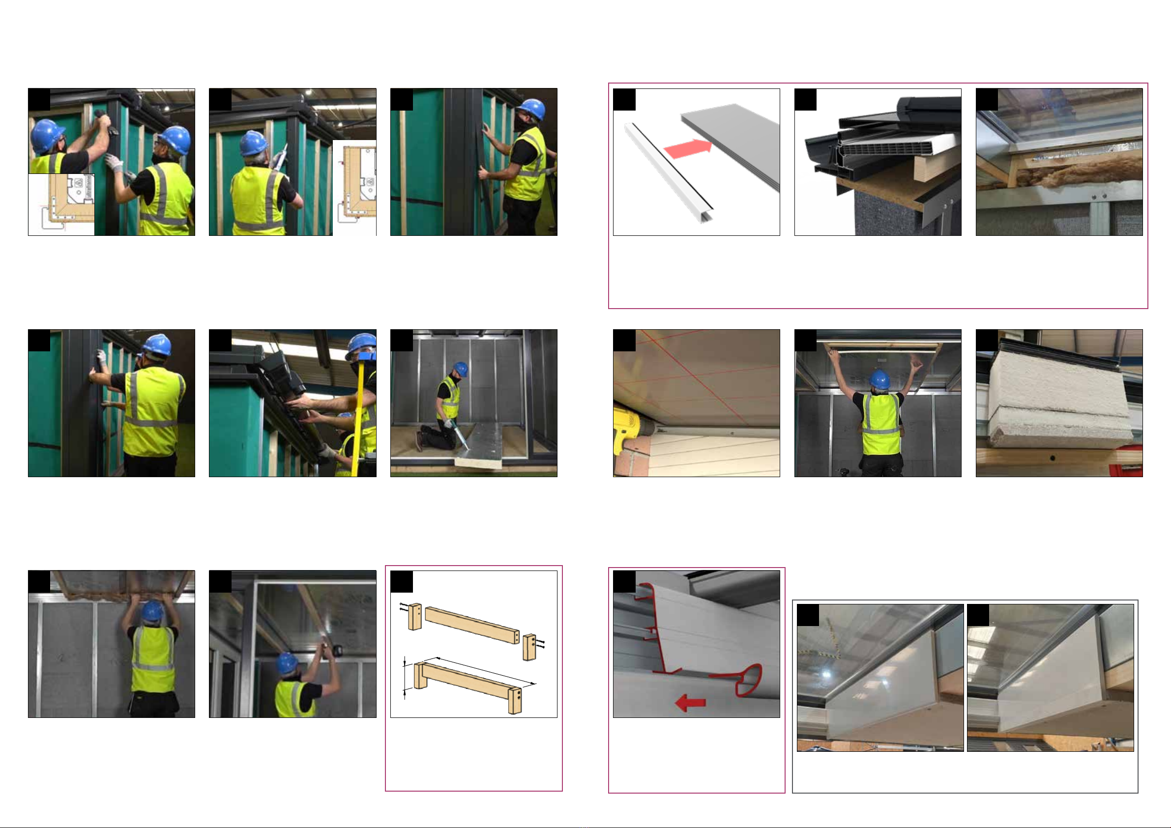
8 9
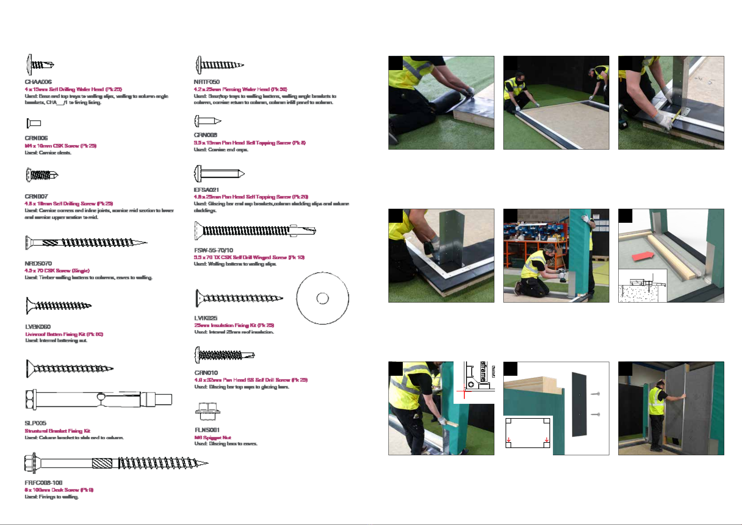
Ensure the walls are pushed against the internal
steel of the base trays and x in position
through the pre punched holes in the base
trays using the provided screws (CHAA006).
12
Installation
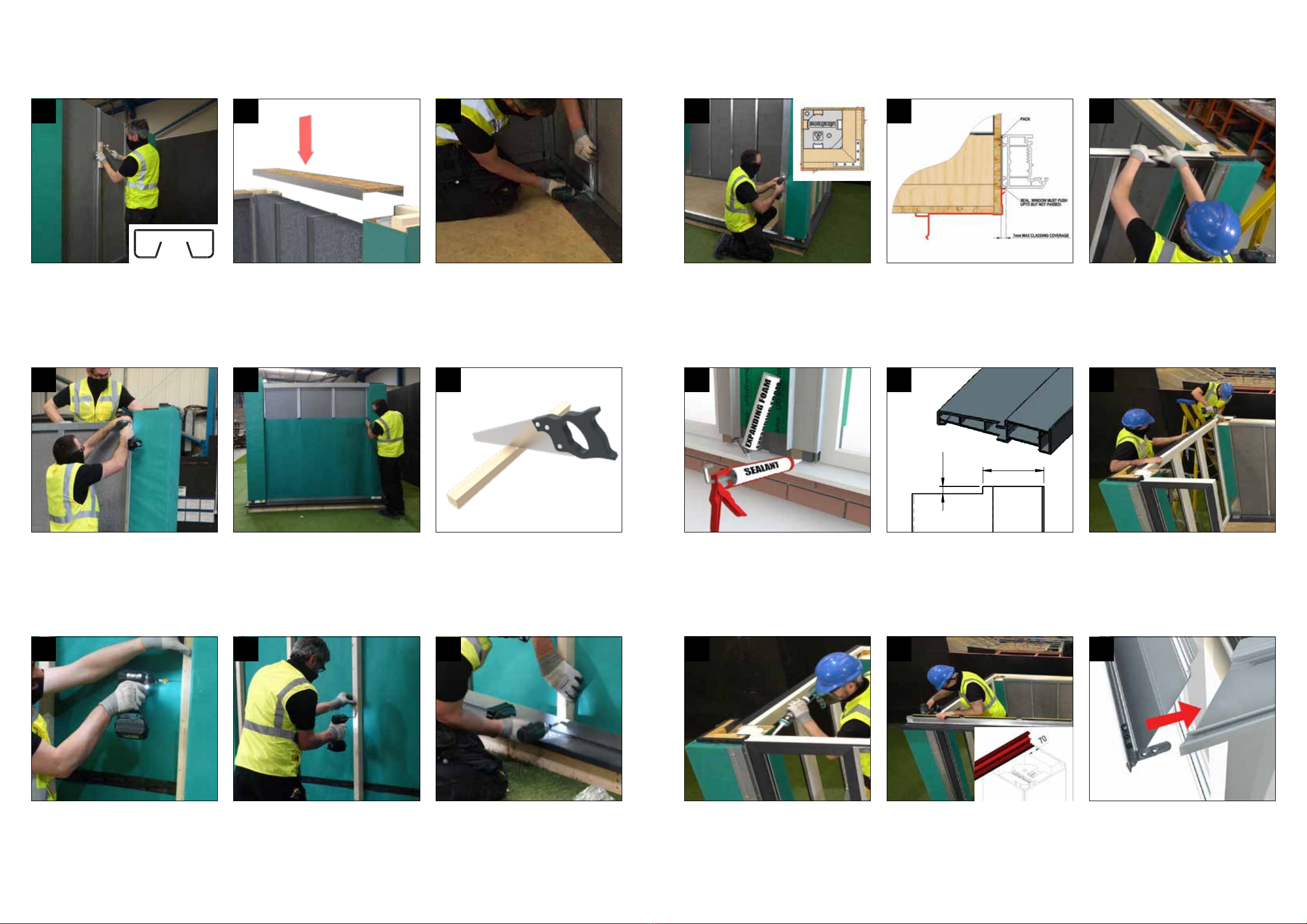
Using the provided roll of membrane, stretch
out horizontally across the lower half of the wall
and temporarily pin in place using staples or
tacks into the corner columns. Repeat across
the upper half of the wall overlapping the lower
covered area. Repeat the process on all walls.
14
Secure the battens to each of the clips by
positioning it behind the base tray and top tray
steels and centred vertically with the walling
panel clips using the provided 5.5mm x 70mm
screws (FSW-55-70/10) towards the top, centre
and bottom of the timber.
17
Cut the 45 x 45mm battens to length, these
should be cut to the same length as the external
walling clips.
15
Secure the column angles and top tray to the
interior wall panels through the pre punched
holes using the supplied 13mm self drilling
screws (CHAA006).
13
Starting with the clips closest to the columns,
x the battens to the columns using provided
xings (NRDS070), pushing the batten up
against the underside of the top tray. The
timbers can then be xed into the walling panel
clips using FSW-55-70/10 towards the top,
centre and bottom of the timber batten.
16
Now secure the top tray and base tray steels
to the timber through the pre punched holes
using 4.2x25mm wafer head screws provided
(NRTF050).
18
Remove the plastic column corners. Fix the
column cladding clips in position aligning the
top edge of the column outer boarding, this
is important to prevent interference when the
eaves beam is tted. Screw x through the
holes into the column using the 4.8 x 25mm
screws provided (EFSA021). These clips can
then be used as a datum point for setting out
the frames.
19
*
*
Position the walling top tray on the walls so that the
internal steel flange is against the walling clips. It may
help at this stage to secure the top tray to the column by
diagonally fixing into the column through the OSB tray
pulling the two components together. Ensure the top
tray is level and flush with the tops of the rear columns.
Fitters Tip: A timber block can be temporarily tted
to the top of the top tray and a clam used to pull the
columns and walling in tight together.
11
Fit the window and door frames into position
against the vertical aluminium clip, ensure
plumb and level and secure using appropriate
xings.
20
Installation
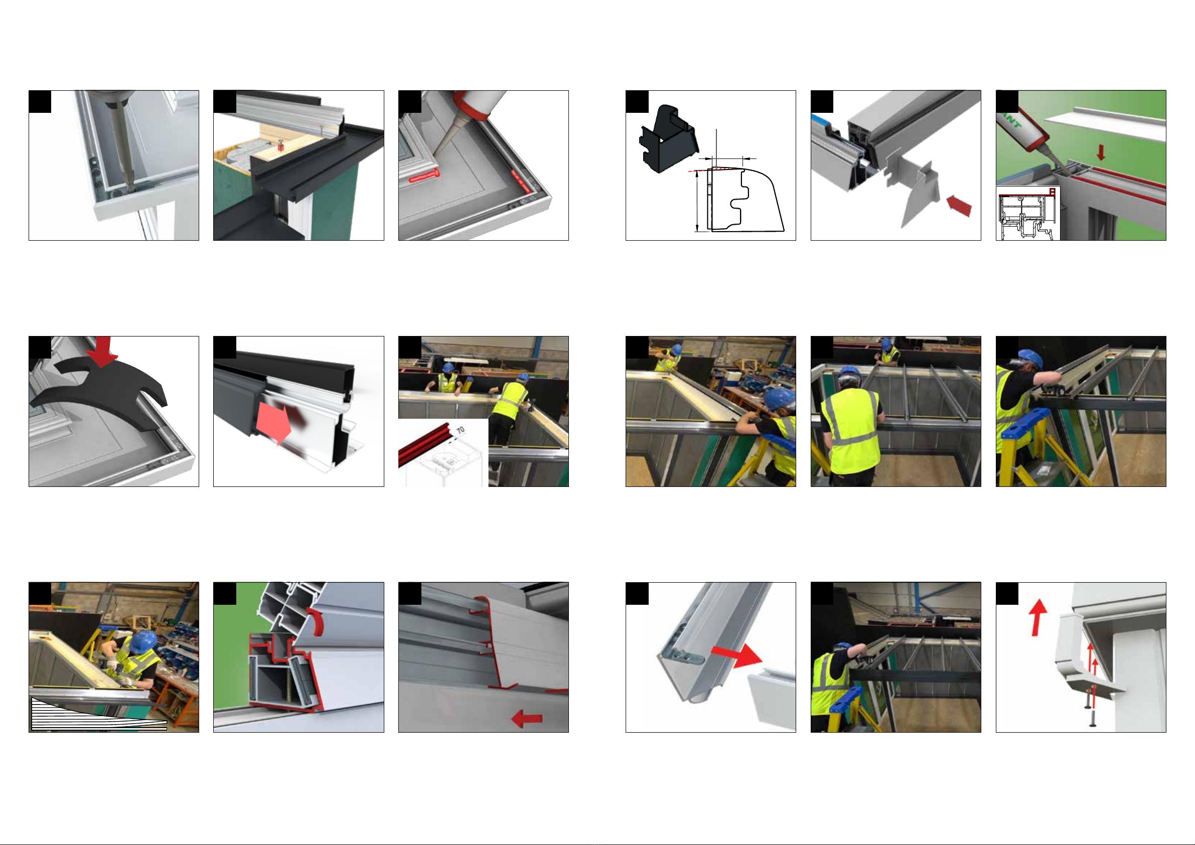
Run a bead of sealant across the top of the
rear and side walls/frames. Position the cill so
that the internal frame datum of the cill lines
through, measure the diagonals to ensure
square and x in place.
24
To t the short cornice returns, start by tting
the cleats and oering up to the tted section.
27
Run a bead of sealant across the top of the
front frames and rear/side cills.
25
72
8.50
Prepare the cill that abuts the tall columns with
the detail shown to accommodate the column
claddings.
23
Locate the front eaves beam (which has a
factory tted lower cornice section) so that the
eaves beam leg is in line with the internal frame
and timber upstands on columns. Fix the eaves
down into the columns and the frames using an
appropriate xing.
26
Weatherseal any joints/gaps under columns/
walls and between windows/doors/walls and
columns. Use foam and/or appropriate sealant.
22
Fit recommended frame addon (15mm min.)
above the front elevation frames.
21
Secure walling panels together using the
provided steel clips both internally and
externally, these can either be pushed into
place or slid down from the tops of the panels.
Ensure the walls are plumb and level.
10
MODEL NAME: 11977 / CONFIG. NAME: 6000mm
ALL DESIGN & OTHER INFORMATION IS CONFIDENTIAL TO & THE PROPERTY OF
ULTRAFRAME (UK) LTD. ALL DESIGN RIGHT, COPYRIGHT & OTHER INTELLECTUAL
PROPERTY RIGHTS IN & TO THE DESIGNS & INFORMATION & ANY CHANGES
THERE TO & DEVELOPMENTS THERE OF BY ULTRAFRAME OR ANY THIRD PARTIES
ARE OWNED BY AND/OR ASSIGNED TO ULTRAFRAME COMPLETELY.
DESCRIPTION:
STOCK CODE:
11977
DRAWING No:
DRAWN BY:
SCALE:
SHEET 1 OF 1, SIZE A3
REV:
STATUS:
DATE CREATED:
ENTERPRISE WORKS, SALTHILL Rd, CLITHEROE, LANCASHIRE, BB7 1PE
1:2
14/04/2021
CAD MODEL IS MASTER
14/04/2021
QM 012, SKETCH SHEET FORMAT, ISSUE 2
Internal
External