Unicorn ENDAT-N3410 User manual

ENDAT‐N3410User’sManual
UNICORNCOMPUTERCORP.
Copyright 2015 Unicorn Computer Corporation. All rights reserved.
1
ENDAT-N3410
For ENDAT-N3410 PCB ver. A01
Document version: 0.7
Release Date: Mar.08.2016

ENDAT‐N3410User’sManual
UNICORNCOMPUTERCORP.
Copyright 2015 Unicorn Computer Corporation. All rights reserved.
2
Copyright notice
The content of this manual has been checked for accuracy. The manufacturer assumes no responsibility
for any inaccuracies that may be contained in this manual. The manufacturer reserves the right to make
improvements or modification to this document and/or the product at any time without prior notice.
No part of this document may be reproduced, transmitted, photocopied or translated into any language,
in any form or by any means, electronic, mechanical, magnetic, optical or chemical, without the prior
written permission of the manufacturer.
Realtek is registered trademark of Realtek Technologies Inc.
Multiscan is a trademark of Sony Corp of America
IBM, EGA, VGA, PC/XT, PC/AT, OS/2 and PS/2 are registered trademarks of International Business
Machines Corporation
Intel® is a registered trademark of Intel Corporation
VIA is registered trademark of VIA Technology Incorporation
Plug and Play is registered trademarks of Intel Corporation
Microsoft, Windows and MS-DOS are trademarks of Microsoft Corporation
Award is a trademark of Phoenix Software Inc.
PCI is a registered trademark of PCI Special Interest Group
Other product names mentioned herein are used for identification purpose only and may be trademarks
and/or registered trademarks of their respective companies.
Installation notice
The manufacturer recommends using a grounded plug to ensure proper motherboard operation. Care
should be used in proper conjunction with a grounded power receptacle to avoid possible electrical
shock. All integrated circuits on this motherboard are sensitive to static electricity. To avoid damaging
components from electrostatic discharge, please do not remove the board from the anti-static packing
before discharging any static electricity to your body, by wearing a wrist-grounding strap. The
manufacturer is not responsible for any damage to the motherboard due to improper operation.

ENDAT‐N3410User’sManual
UNICORNCOMPUTERCORP.
Copyright 2015 Unicorn Computer Corporation. All rights reserved.
3
ENDAT‐N3410
........................................................................................................ 1
DISCLAIMER................................................................................................................... 6
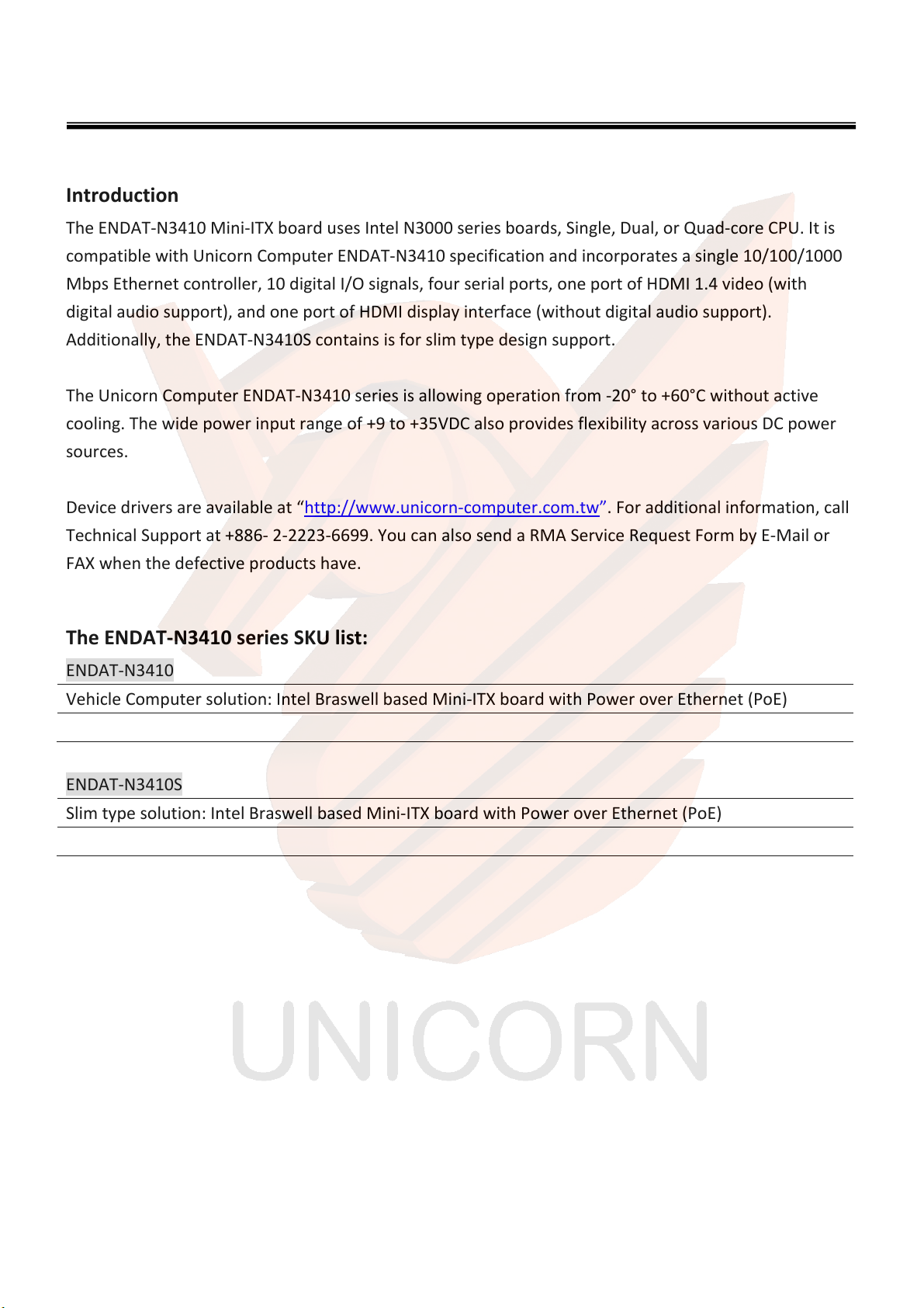
Introduction .....................................................................................................................................................................7
The ENDAT-N3410 series SKU list: ...................................................................................................................................7
1.PRODUCTDESCRIPTION............................................................................................. 8
1.1.PRODUCT SPECIFICATIONS ............................................................................................ 8
1.2.BOARD LAYOUT ......................................................................................................... 9
1.3.COMPONENTS LIST ................................................................................................... 11
1.4.BLOCK DIAGRAM...................................................................................................... 12
2.TECHNICALREFERENCE............................................................................................ 13
2.1.PROCESSOR............................................................................................................ 13
2.2.SYSTEMMEMORY .................................................................................................... 14
2.3.MEMORYRESOURCES ............................................................................................... 16
2.4.PROCESSORGRAPHICSSUBSYSTEM ............................................................................... 17
2.4.1.INTEGRATED GRAPHICS .............................................................................................. 17
2.5.USB3.0AND2.0HOSTCONTROLLER .............................................................................. 18
2.5.1.USB 3.0 PORTS:........................................................................................................ 18
2.5.2.USB 2.0 PORTS:........................................................................................................ 18
2.6.SATAINTERFACE...................................................................................................... 19
2.7.REAL‐TIMECLOCKSUBSYSTEM ..................................................................................... 20
2.8.AUDIOSUBSYSTEM................................................................................................... 21
2.9.LANSUBSYSTEM ...................................................................................................... 22
2.10.HARDWAREMONITORING .......................................................................................... 23
2.11.ACPI..................................................................................................................... 24
2.12.HARDWARESUPPORT ............................................................................................... 27
3.ONBOARD ............................................................................................................ 28

ENDAT‐N3410User’sManual
UNICORNCOMPUTERCORP.
Copyright 2015 Unicorn Computer Corporation. All rights reserved.
4
3.1.CONNECTORSANDHEADERS ....................................................................................... 28
3.2.JUMPER SETTING...................................................................................................... 31
3.3.PIN HEADER DEFINED ................................................................................................ 34
4.APPENDIX............................................................................................................. 45
4.1.WDT AND DIGITAL I/O PROGRAMMING ........................................................................... 45

ENDAT‐N3410User’sManual
UNICORNCOMPUTERCORP.
Copyright 2015 Unicorn Computer Corporation. All rights reserved.
5
RevisionHistory
Revision Description Date
0.1 Initial release of the Mini-ITX boards with Intel “Braswell” SOC. Sep 30, 2015
0.2 Fix description errors Oct 02, 2015
0.3 Changed power input voltages to 9-35V. Oct 05, 2015
0.4 Add programming guide for GPIO and WDT function. Dec 17, 2015
0.5 Modified information and add connector defined for VGA and JFP1, Feb 25, 2016
0.6 Add procedure for BIOS refresh. Mar 06, 2016
0.7 Changed label for KB/MS and Audio Line-in. Mar 08, 2016

ENDAT‐N3410User’sManual
UNICORNCOMPUTERCORP.
Copyright 2015 Unicorn Computer Corporation. All rights reserved.
6
Disclaimer
This product specification applies to only the Unicorn Computer ENDAT-N3410 series.
All Unicorn Computer Boards are evaluated as Information Technology Equipment (I.T.E.) for use in
personal computers (PC) for installation in homes, computer rooms, and similar locations.
The suitability of this product for other PC or embedded non-PC applications or other environments,
such as medical, industrial, alarm systems, test equipment, etc. may not be supported without further
evaluation by Unicorn Computer.
Unicorn Computer Corporation may have patents or pending patent applications, trademarks,
copyrights, or other intellectual property rights that relate to the presented subject matter.
The furnishing of documents and other materials and information does not provide any license, express
or implied, by estoppel or otherwise, to any such patents, trademarks, copyrights, or other intellectual
property rights.
Unicorn Computer may make changes to specifications and product descriptions at any time, without
notice.
Designers must not rely on the absence or characteristics of any features or instructions marked
“reserved” or “undefined.” Unicorn Computer reserves these for future definition and shall have no
responsibility whatsoever for conflicts or incompatibilities arising from future changes to them.

ENDAT‐N3410User’sManual
UNICORNCOMPUTERCORP.
Copyright 2015 Unicorn Computer Corporation. All rights reserved.
7
Introduction
The ENDAT-N3410 Mini-ITX board uses Intel N3000 series boards, Single, Dual, or Quad-core CPU. It is
compatible with Unicorn Computer ENDAT-N3410 specification and incorporates a single 10/100/1000
Mbps Ethernet controller, 10 digital I/O signals, four serial ports, one port of HDMI 1.4 video (with
digital audio support), and one port of HDMI display interface (without digital audio support).
Additionally, the ENDAT-N3410S contains is for slim type design support.
The Unicorn Computer ENDAT-N3410 series is allowing operation from -20° to +60°C without active
cooling. The wide power input range of +9 to +35VDC also provides flexibility across various DC power
sources.
Device drivers are available at “http://www.unicorn-computer.com.tw”. For additional information, call
Technical Support at +886- 2-2223-6699. You can also send a RMA Service Request Form by E-Mail or
FAX when the defective products have.
TheENDAT‐N3410seriesSKUlist:
ENDAT-N3410
Vehicle Computer solution: Intel Braswell based Mini-ITX board with Power over Ethernet (PoE)
ENDAT-N3410S
Slim type solution: Intel Braswell based Mini-ITX board with Power over Ethernet (PoE)

ENDAT‐N3410User’sManual
UNICORNCOMPUTERCORP.
Copyright 2015 Unicorn Computer Corporation. All rights reserved.
8
1. Product Description
1.1. Product Specifications
ModelnameENDAT‐N3410/ENDAT‐N3410S(Braswell)
MicroprocessorIntelBraswellM/D
Memory2XSODIMMDDR3LDualchannelsupport8GB(max)
CRTinterfaceVGA/DualHDMI/DualCh.LVDSsupport,
PanelTypeselectedbySystemBIOS
GFXcoreIntelgraphicsHD
SystemChipBraswellM/D
ETHERNETDualIntel82583V2xGbE10/100/1000M(supportEtherCAT(optinal))
SATA
2xportSATA3interfacesharew/1xportmSATAwithHi‐SpeedSwitch
byjumperselect
GPIO8bitin/out
Serial4SerialPortsw/+5,+12VPowerselect,COM2/COM3support
RS232/422/485bySystemBIOS;theCOM2~COM4areboxheadertype
USB2.0/USB3.08USBportsinclude6USB2.0+2USB3.0
Other2xPOE
EXPANSIONSLOT2mini‐PCIesocketdesignwithOneFullandOneHalf
2xPoE+RJ‐45connector
COM1,2xHDMI,1xVGA(ForENDAT‐N3410)
USB2.0x4(ENDAT‐N3410S:USB2.0x2),USB3.0x2
I/OPORT(RearWindow)
DCJack
2.00mmBoxHeadersupportCOM2~COM4
2.00mmPinHeadersuppotLine‐In,Line‐Out,MIC‐inandSpeakerout
2.00mmPinHeadersuppotUSB2.0x2
BOXHeader/Header
2.00mmBoxHeaderforLPT;2.00mmPinHeaderforPS2KB/MS
POWERSUPPLYWiderangeDC9‐35Vinput
BoardSizemini‐iTXformfactorof170mmx170mm
Figure1 - Product specifications

ENDAT‐N3410User’sManual
UNICORNCOMPUTERCORP.
Copyright 2015 Unicorn Computer Corporation. All rights reserved.
9
1.2. Board Layout
Show the location of the major components on the top-side of Unicorn Board ENDAT-N3410.
Figure2 - Board Components
“▪” Represents the 1st Pin.

ENDAT‐N3410User’sManual
UNICORNCOMPUTERCORP.
Copyright 2015 Unicorn Computer Corporation. All rights reserved.
10
• Back panel I/O connectors
This section describes the board’s connectors and headers. The connectors and headers can be divided
Figure3–RearI/OforN3410
Figure4–RearI/OforN3410S
Item Description
A DC +9 V to +35 V Power Jack
B Ethernet RJ-45 (Without LED)
C Ethernet RJ-45 (Without LED)
D Four or Two Port USB 2.0 Connector (Option by model number)
T Two Port USB 3.0 Connector
F HDMI1 Connector (DDI0 )
G VGA Connector (DDI2,this for “N3410” only)
H HDMI2 Connector (DDI1 )( Option: Switch LVDS by H/W BOM Changed)
I Serial Port1 (Serial console function support)

ENDAT‐N3410User’sManual
UNICORNCOMPUTERCORP.
Copyright 2015 Unicorn Computer Corporation. All rights reserved.
11
1.3. Components List
List all Jumper and Pins
Item/calloutfromDescription
JCMOS CMOS Data Clear
JBAT1 RTC Timer Clear
JP1 LCD Power
JP2 LVDS Inverter power
JP3 SATA#1, 5V selected (SATA DOM, pin7with power selected by jumper)
JP4 SATA#2, 5V selected (SATA DOM, pin7with power selected by jumper)
JP6 for and power select via pin#9 of JCOM1,2
JP7 for and power select via pin#9 of JCOM1,2
JP8 LVDS back-light select
JFP1 Front Panel, (Power LED, External Buzzer, Reset, PWBTN, SIO Enabled select)
JMPCIEVER1 Mini-PCI Slot 1.1 and 2.0 select.
J1 MIC / Line-In audio connector
J2 Speaker /LM1877Amplifier audio connector
J3 Digital I/O header
JKBMS Keyboard / Mouse header
JCPUFAN1 Processor fan header
JSYSFAN1 System fan header
SMB1 SM-bus Header
JCOM2 Serial port 2 Box Header
JCOM3 Serial port 3 Box Header
JCOM4 Serial port 4 Box Header
JLPT1 Parallel Port Box Header
JUSB1 USB 2.0 header
JUSB2 USB 2.0 header
JLVDS LVDS Socket Connectors
HDDPWR2 HDD Power
Table 1: Onboard jumper setting for PCB: A0

ENDAT‐N3410User’sManual
UNICORNCOMPUTERCORP.
Copyright 2015 Unicorn Computer Corporation. All rights reserved.
12
1.4. Block Diagram
Block diagram of the major functional areas of the board.
Figure5 - Block Diagram

ENDAT‐N3410User’sManual
UNICORNCOMPUTERCORP.
Copyright 2015 Unicorn Computer Corporation. All rights reserved.
13
2. Technical Reference
2.1. Processor
Unicorn Computer ENDAT-N3410 has a soldered-down System-on-a-Chip (SoC), which consists of a
dual-core Intel Celeron processor N3150 with up to 6 W TDP.
• Integrated graphics
• Integrated memory controller
• Integrated PCH
Processor Number N3700 N3000 N3050 N3150
Cache 2 MB L2 Cache 2 MB L2 Cache 2 MB L2 Cache 2 MB L2 Cache
Instruction Set 64-bit 64-bit 64-bit 64-bit
Lithography 14 nm 14 nm 14 nm 14 nm
# of Cores 4 2 2 4
# of Threads 4 2 2 4
Processor Base Frequency 1.6 GHz 1.04 GHz 1.6 GHz 1.6 GHz
Burst Frequency 2.4 GHz 2.08 GHz 2.16 GHz 2.08 GHz
TDP 6 W 4 W 6 W 6 W
Table 2: SOC SKU list
NOTE:
This board has specific requirements for providing power to the processor.

ENDAT‐N3410User’sManual
UNICORNCOMPUTERCORP.
Copyright 2015 Unicorn Computer Corporation. All rights reserved.
14
2.2.
2.2. System Memory
The board has two 204-pin SO-DIMM sockets and supports the following memory features:
•1.35 V DDR3L up to 1600 MHz SDRAM SO-DIMM with gold plated contacts on Intel Celeron processor N3000
series.
•Support for 1066 MHz/1600 MHz memory speeds
• Dual memory channel
• Unbuffered, single-sided or double-sided SO-DIMMs
• Each channel was up8 GB maximum total system memory (with 4 Gb memory technology). Refer to Section
BIOS SETUP on the total amount of addressable memory.
•Minimum recommended total system memory: 1024 MB
•Non-ECC SO-DIMMs
•Serial Presence Detect
NOTE:
If you install 1333 MHz, it will run at 1066 MHz
Supported Memory Configurations SO-DIMM
Capacity Configuration
(Note)
SDRAM Density SDRAM Organization
Front-side/Back-side
Number of SDRAM
Devices
1024 MB SS 1 Gbit 128 M x8/empty 8
2048 MB DS 1 Gbit 128 M x8/128 M x8 16
2048 MB SS 2 Gbit 256 M x8/empty 8
4096 MB DS 2 Gbit 256 M x8/256 M x8 16
4096 MB SS 4 Gbit 512 M x8/empty 8
8192 MB DS 4 Gbit 512 M x8/512 M x8 16
Table 3: list the supported SD-DIMM configuration
NOTE:
To be fully compliant with all applicable DDR SDRAM memory specifications, if non-SPD memory is installed, the
BIOS will attempt to correctly configure the memory settings, but performance and reliability may be impacted or
the SO-DIMMs may not function under the determined frequency.

ENDAT‐N3410User’sManual
UNICORNCOMPUTERCORP.
Copyright 2015 Unicorn Computer Corporation. All rights reserved.
15
A.MemoryInstall
Figure 6 - Install a memory DIMM.
Note:
1. The DIMM must be installed to DIMMA1 slot first.
2. If the DIMM does not go in smoothly, do not force it. Pull it all the way out and try again.
B.MemoryCapacity
DIMM Socket Location DDR3L Module Total Memory Size:
DIMMA1: 512MB/1GB/2GB/4GB/8GB
DIMMB1: 512MB/1GB/2GB/4GB/8GB Max is 8GB
C.DualChannelMemoryInstallation
Please refer to the following requirements to activate Dual Channel function:
Install memory module of the same density in pairs, shown in the table.

ENDAT‐N3410User’sManual
UNICORNCOMPUTERCORP.
Copyright 2015 Unicorn Computer Corporation. All rights reserved.
16
2.3. Memory Resources
Addressable Memory
The board utilizes up to 8 GB of addressable system memory. Typically the address space that is
allocated for PCI Conventional bus add-in cards, PCI Express configuration space, BIOS (SPI Flash device),
and chipset overhead resides above the top of DRAM (total system memory). On a system that has 8 GB
of system memory installed, it is not possible to use all of the installed memory due to system address
space being allocated for other system critical functions. These functions include the following:
• BIOS/SPI Flash device (64 Mbit)
• Local APIC (19 MB)
• Direct Media Interface (40 MB)
• PCI Express configuration space (256 MB)
• SoC base address registers PCI Express ports (up to 256 MB)
• Memory-mapped I/O (I/O fabric) that is dynamically allocated for PCI Express add-in cards (256 MB)
The board provides the capability to reclaim the physical memory overlapped by the memory mapped
I/O logical address space. The board remaps physical memory from the top of usable DRAM boundary to
the 4 GB boundary to an equivalent sized logical address range located just above the 4 GB boundary. All
installed system memory can be used when there is no overlap of system addresses.

ENDAT‐N3410User’sManual
UNICORNCOMPUTERCORP.
Copyright 2015 Unicorn Computer Corporation. All rights reserved.
17
2.4. Processor Graphics Subsystem
The board supports graphics through Intel HD Graphics.
2.4.1. Integrated Graphics
The board supports integrated graphics via the processor.
Intel® High Definition (Intel® HD) Graphics
The Intel HD graphics controller features the following:
I. HDMI 1.4b
II. 3D graphics hardware acceleration supporting DirectX*11.1, OpenCL* 1.2, OGL ES Halti/2.0/1.1, OpenGL* 4.2
III. Video decode hardware acceleration supporting H.265/HEVC @ Level 5, H.264 @ Level 5.2, MPEG2, MVC, VC-1, WMV9
IV. Video encode hardware acceleration supporting H.264 @ Level 5.1, JPEG and MVC formats JPEG and VP8 formats
V. High-Bandwidth Digital Content Protection (HDCP) 1.4/2.2 support for content protection
Video Memory Allocation
Intel® Dynamic Video Memory Technology (DVMT) is a method for dynamically allocating system
memory for use as graphics memory to balance 2D/3D graphics and system performance. If your
computer is configured to use DVMT, graphics memory is allocated based on system requirements and
application demands (up to the configured maximum amount). When memory is no longer needed by
an application, the dynamically allocated portion of memory is returned to the operating system for
other uses.
High Definition Multimedia Interface* (HDMI*)
The HDMI port supports standard, enhanced, or high definition video, plus multi-channel digital audio
on a single cable. The port is compatible high resolution and maximum supported resolution is 3840 x
2160 @ 30 Hz and 2560 x 1600 @ 60 Hz, 24 bpp (WUXGA). The HDMI port is compliant with the HDMI
1.4b specification.
Integrated Audio Provided by the HDMI Interfaces
The following audio technologies are supported by the HDMI 1.4b interfaces directly from the SoC:
• AC3 - Dolby* Digital and Dolby Digital Plus
• This HDMI audio support on HDMI only.

ENDAT‐N3410User’sManual
UNICORNCOMPUTERCORP.
Copyright 2015 Unicorn Computer Corporation. All rights reserved.
18
2.5. USB 3.0 and 2.0 host controller
The USB port arrangement is as follows:
2.5.1. USB 3.0 ports:
Two ports are implemented with external front panel connectors (one blue and one orange charging capable)
Two ports are implemented with external back panel connectors (blue)
Maximum current is 900 mA for each blue port.
2.5.2. USB 2.0 ports:
Four ports are implemented with external back panel connectors (Black)
Maximum current is 500 mA for each port (2 A total)
Two ports via one dual-port internal 1x8 1.25 mm pitch header (Black)
Maximum current is 500 mA for each port of the header (1 A total)
Two ports via two dual-port internal Mini-Card Slot.
Maximum current is 500 mA for each port of the Mini-Card Socket. (1 A total)
All the USB ports are high-speed, full-speed, and low-speed capable (in OS).
NOTE:
Computer systems that have an unshielded cable attached to a USB port may not meet FCC Class B requirements, even if no
device is attached to the cable. Use a shielded cable that meets the requirements for full-speed

ENDAT‐N3410User’sManual
UNICORNCOMPUTERCORP.
Copyright 2015 Unicorn Computer Corporation. All rights reserved.
19
2.6. SATA Interface
The SoC provides one SATA port with a theoretical maximum transfer rate of 6 Gb/s. A point-to-point
interface is used for host to device connections.
The underlying SATA functionality is transparent to the operating system. The SATA controller can
operate in both legacy and native modes. In legacy mode, standard IDE I/O and IRQ resources are
assigned (IRQ 14 and 15). In Native mode, standard PCI Conventional bus resource steering is used.
Native mode is the preferred mode for configurations using Windows* operating systems.
• AHCI Mode
The board supports AHCI storage mode.
NOTE:
In order to use AHCI modes, AHCI mode force enabled in the BIOS. Microsoft* Windows 8 includes the necessary AHCI
drivers without the need to install separate AHCI drivers during the operating system installation process. However, it is
always good practice to update the AHCI drivers to the latest available by Intel.
• Pin 7 power designs for SATA modules
Power Pin 7 Design can be incorporated in all of our SATA DOM storage devices. Traditionally, a serial
ATA device is connected to a board through a cable from the power supply. We support the SATA can
switch with Power on Pin 7 by jumper, making it possible to plug your flash storage device onto your
board without the need for any external cable.

ENDAT‐N3410User’sManual
UNICORNCOMPUTERCORP.
Copyright 2015 Unicorn Computer Corporation. All rights reserved.
20
2.7. Real-Time Clock Subsystem
A coin-cell battery (CR2032) powers the real-time clock and CMOS memory. When the computer is not
plugged into a wall socket, the battery has an estimated life of three years. When the computer is
plugged in, the standby current from the power supply extends the life of the battery. The clock is
accurate to ± 13 minutes/year at 25 ºC with 3.3 VSB applied via the power supply 5 V STBY rail.
NOTE:
1. If the battery and AC power fail, date and time values will be reset and the user will be notified during the POST.
2. When the voltage drops below a certain level, the BIOS Setup program settings stored in CMOS RAM (for example, the
date and time) might not be accurate. Replace the battery with an equivalent one.
This manual suits for next models
1
Table of contents
Popular Desktop manuals by other brands

Moxa Technologies
Moxa Technologies DA-681 Series user manual

J.Burrows
J.Burrows STILFORD JBSTIHA14 Assembly instructions

Motorola
Motorola F5208 user guide

Toshiba
Toshiba Satellite L300 Series Maintenance manual

CTC Parker Automation
CTC Parker Automation PC9 Installation

Splicecom
Splicecom PCS 100 user manual