Unigraf UCD-422 User manual

UCD Console
for
UCD-422
User Manual

UCD Console for UCD-422 User Manual
2.
Copyright
This manual, Copyright © 2020 Unigraf Oy. All rights reserved
Reproduction of this manual in whole or in part without a written permission of
Unigraf Oy is prohibited.
Notice
The information given in this manual is verified in the correctness on the date of issue. The
authors reserve the rights to make any changes to this product and to revise the information
about the products contained in this manual without an obligation to notify any persons about
such revisions or changes.
Edition
UCD Console for UCD-422 User Manual, Version 4
Date: 5 October 2020
Company Information
Unigraf Oy
Piispantilankuja 4
FI-02240 ESPOO
Finland
Tel. +358 9 859 550
mailto:info@unigraf.fi
https://www.unigraf.fi
http://www.unigraf-china.cn

UCD Console for UCD-422 User Manual
3.
Trademarks
Unigraf, UCD, UCD-422 and TSI are trademarks of Unigraf Oy.
HDMI is a trademark of HDMI Licensing, LLC.
HDCP is a trademark of Digital Content Protection LLC.
Altera and Intel FPGA are trademarks of Intel Corporation or its subsidiaries in the U.S. and/or
other countries
Windows® 10, Windows® 8, Windows® 7 and Windows® XP are trademarks of
Microsoft Corporation.
DisplayPort™ and the DisplayPort™ logo are trademarks owned by the
Video Electronics Standards Association (VESA®) in the United States and other countries.
All other trademarks are properties of their respective owners.
Limited Warranty
Unigraf warrants its hardware products to be free from defects in workmanship and materials,
under normal use and service, for twelve (12) months from the date of purchase from Unigraf
or its authorized dealer.
If the product proves defective within the warranty period, Unigraf will provide repair or
replacement of the product. Unigraf shall have the whole discretion whether to repair or
replace, and replacement product may be new or reconditioned. Replacement product shall be
of equivalent or better specifications, relative to the defective product, but need not to be
identical. Any product or part repaired by Unigraf pursuant to this warranty shall have a
warranty period of not less than 90 days, from the date of such repair, irrespective of any
earlier expiration of original warranty period. When Unigraf provides replacement, then the
defective product becomes the property of Unigraf.
Warranty service may be obtained by contacting Unigraf within the warranty period. Unigraf
will provide instructions for returning the defective product.
CE Mark
UCD-422 products meet the essential health and safety requirements, is in conformity with and
the CE marking has been applied according to the relevant EU Directives using the relevant
section of the corresponding standards and other normative documents.

UCD Console for UCD-422 User Manual
4.
Table of Contents
About This Manual...........................................................................................5
Purpose.....................................................................................................5
Product and Driver Version.......................................................................5
Notes.........................................................................................................5
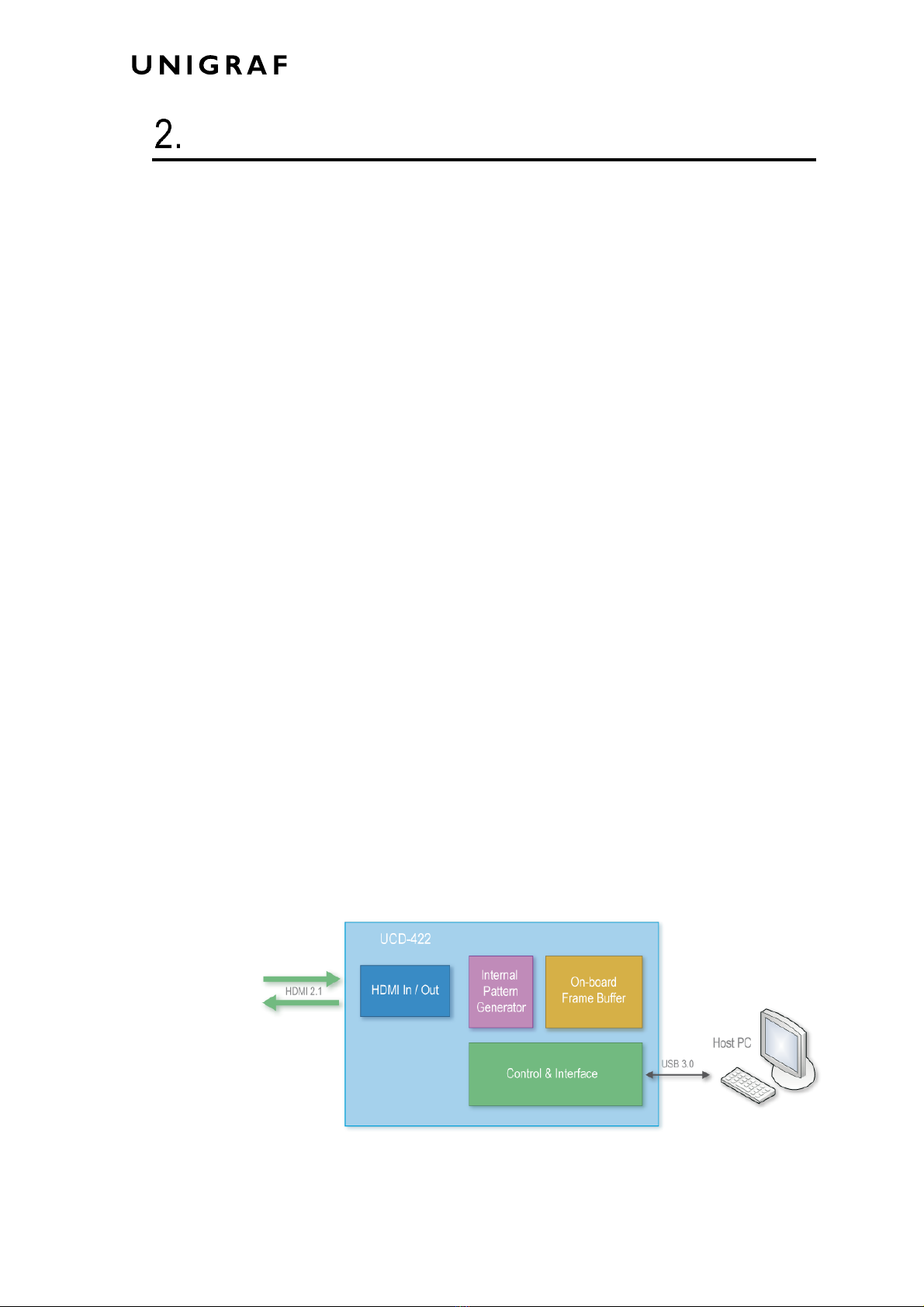
Introduction......................................................................................................6
Unpacking.................................................................................................8
Installation Package..................................................................................8
Software Installation..................................................................................8
License Manager.............................................................................................9
Firmware Update Procedure..........................................................................11
UCD Console.................................................................................................14
Options.................................................................................................... 15
HDMI Reference Sink....................................................................................17
Video Tab................................................................................................17
Audio Tab................................................................................................20
Link Tab.................................................................................................. 22
EDID Tab................................................................................................24
HDCP Tab...............................................................................................26
InfoFrame Tab ........................................................................................ 27
Source DUT Testing Tab ........................................................................28
HDMI Reference Source................................................................................29
Pattern Generator Tab............................................................................29
Audio Generator Tab...............................................................................32
Link Tab.................................................................................................. 33
EDID Tab................................................................................................35
HDCP Tab...............................................................................................37
Event Log.......................................................................................................38
EDID Editor....................................................................................................39
Appendix A. Product Specification..................................................................................41
UCD-422.................................................................................................41
Appendix B. Licensing....................................................................................................42
Appendix C: Predefined Timings ....................................................................................44
Appendix D: Predefined Patterns ...................................................................................46
Appendix E: Firmware Update Procedure with Quartus Prime.......................................47
Downloading the Firmware .....................................................................47
FW Update Tool......................................................................................47
Connect to the UCD-422 Unit .................................................................48
Programming the FW..............................................................................49

About This Manual
5.
ABOUT THIS MANUAL
Purpose
This guide is User Manual of UCD-422, USB-connected video interface test unit for use
with a PC with Windows® 10 Windows® 8 or Windows® 7 operating system.
The purpose of this guide is to
•Provide an overview of the product and its features.
•Provide instructions for the user on how to install the software and the drivers.
•Provide instructions for the user on how to update the FW of the unit.
•Introduce the HW features of the UCD-422 units.
•Provide instructions for the user on how to use UCD Console software.
Product and Driver Version
This manual explains features found in UCD Console Software Package 1.9. Please consult
Unigraf for differences or upgrades of previous versions.
Please consult the Release Notes document in the installation package for details of the SW
and FW versions and changes to previous releases.
Notes
On certain sections of the manual, when important information or notification is given, text
is formatted as follows. Please read these notes carefully.
Note This text is an important note

Introduction
6.
INTRODUCTION
Product Description
UCD-422 is a USB 3.0 connected video interface test unit with HDMI 2.1 Pattern
Generator and Analyzer capability. UCD Console is the common graphical user interface
(GUI) for Unigraf’s UCD-400 and UCD-300 family units. The outlook and details of
UCD Console will be different depending on the capabilities of the connected UCD unit
reflecting the features enabled.
UCD-400 family feature a high-level Software Development Kit (SDK) for use in
automated testing. It is called Test Software Interface (TSI). TSI allows for an easy
integration of Production and R&D testing routines into an automated test system
environment. Please refer to TSI documentation found in additional Unigraf manuals for
more details.
Product Features
•High resolution video and audio capture up to 10k30Hz, 8k60Hz, 4K/UHD 120 Hz
•Supports FRL
•Supports Auto Low Latency Mode (ALLM) and Variable Refresh rate (VRR)
•Compatible with HDCP versions 1.4 and 2.3
•2 GB on-board high-speed video buffer
•High speed USB 3.0 host PC interface
Please refer to Product Specifications in the appendix of this document for details.
Functional Description
UCD-422 units consist of a multimedia signal input stage, an internal pattern generator, a
control stage with on-board frame buffer and a PC interface stage. In the Input Stage the
signal is conditioned and converted to desired format. The Interface and Control stages are
either passing the captured data directly to the USB interface or storing it to the frame
buffer. The internal pattern generator is able to source a signal for testing sink and branch
units. The Interface & Control stages are receiving instructions from the host PC to
configure and control the functionality of the unit.
Please find below logical diagram of UCD-422 unit

Introduction
7.
UCD-422
The image below indicates the connections in UCD-422 unit and their description.
Name
Description
HDMI in
HDMI 2.1 compliant input from the upstream Source
HDMI out
HDMI 2.1 compliant output to the downstream Sink
Power in
+12 Vdc Power Supply Input
Power On/Off
Rocker power switch
USB
USB 3.0 connection to the host PC
Programmer
USB interface used in device FW update (behind a cover)
Ethernet
Ethernet interface used in device FW update (behind a cover)
Note Capturing and sourcing high resolution video modes, especially 4K and 8K video
modes and the 120 Hz frame rate set stringent requirements on the video cables and
connectors.
Warning In order to avoid damage to the unit and the PC, please always attach the power
cord (Power In) to the unit first, and after that connect the USB cable to the PC.

Introduction
8.
Unpacking
The UCD-422 product shipment contains:
•The UCD-422 unit
•AC/DC Power supply (100 to 240 Vac 50/60 Hz input, +12 Vdc output)
•USB 3.0 compliant cable for host PC connection
•HDMI 2.1 grade HDMI cable
•Micro-USB type B compatible cable needed for FW programming
•Ethernet cable needed for FW programming
Installation Package
The UCD-422 software installation package can be obtained from Unigraf download page
at https://www.unigraf.fi/support/download-links. Please log in with the following
credentials before attempting to access the download page:
Username: unigraf
Password: ruukintie
The installation package is a bundle between the components needed for UCD Console and
for TSI SDK. The bundle contains the following items:
•Windows drivers (installed during set up)
•UCD Console software GUI (installed during set up)
•License Manager (installed during set up)
•TSI SDK
•UCD-422 firmware (FW) matching UCD Console version (copied during set up)
•User Manuals including this document.
When launched, UCD Console verifies that the firmware (FW) version programmed to
UCD-422 matches the launched version. If conflict, UCD Console informs the user. If FW
update is needed please refer to Firmware Update Procedure later in this manual for
instructions.
Note: The software should be installed before connecting the UCD-422 unit in the PC.
Note: System administrator's privileges are required for performing the installation.
Software Installation
Start the installation by running Unigraf Software Bundle Setup.exe
Once the installer has started, a welcome page is displayed. The welcome page shows the
software package release version.
Click Next to continue. The next two dialogs are used to define the installation folder in
your PC and the Start Menu folder used.
When the selections are ready, click Install to start the installation.
Click Finish to exit the installation dialog.

License Manager
9.
LICENSE MANAGER
Licensing
The features of UCD Console GUI are divided into groups based on the target use of the
device. Some basic features can be used without licenses. Advanced feature groups have
their dedicated licenses that open the related part of the GUI or enable the related control.
Unigraf licenses are provided as strings of characters, License Keys. Each License Key
enables a dedicated function in one device. Each device has its dedicated Seed Number.
Each License Key is tied to one Seed Number. License Keys can be freely used in any
number of PCs.
License keys are managed with Unigraf License Manager. By default, shortcut to Unigraf
License Manager can be found in Start Menu under: All programs/Unigraf/UCD-400.
Please click Yes in the first dialog. License Manager can be run only with Administrator
rights.
Note: System administrator's privileges are required for accessing the licenses.
License Manager GUI
When run, License Manager will list the licensing enabled Unigraf devices. If no suitable
device families are detected, License Manager will exit. Please first select one of the
available device families by clicking one of the device family selector buttons.
In the list of Attached Devices please select the device in question. The serial number and
the seed number of your device are printed in a sticker attached to the bottom of the device.
The Back button opens the device family selection screen. The Refresh button will re-scan
the system for installed hardware.

License Manager
10.
Managing Licenses
Seed Number
Each license is tied to a hardware unit with the help of the Seed Number. Each unit has a
unique Seed Number. Seed Number of the selected unit can be found in the top of the
dialog.
Seed Number of the selected device can be copied from dialog link for e.g. ordering
Licenses.
Adding New License Keys
To add a new license key for a device, please enter the characters from the license sticker to
the boxes provided. The License Manager will automatically move the caret across the edit
boxes during typing. If the key is given in text format, copy it and paste to the leftmost box.
Once the license key is fully entered, click the Install. The license is authenticated and if it
is valid, the license will appear in the list of installed licenses. If the key fails to
authenticate, an error message is displayed. If this happens, please make sure that the key
has been typed correctly and that the seed number on the license key sticker matches the
seed number displayed seed number for the device.
Please note that to avoid confusion, some letters will never appear in a license key because
they resemble numbers: For example, capital 'G' and number '6' are very similar when
printed with small font. When in doubt, use numbers.
Also, please notice, that characters that can't be part of valid license key are not accepted as
input. When appropriate an automatic conversion is applied while typing: For example,
lower case letters are converted to upper case automatically.
Managing Installed Licenses
The Installed licenses list shows all currently installed licenses for the currently selected
device. The list shows the actual license key, and what that key unlocks.
Remove Selected will uninstall selected licenses. To uninstall a license, click on the license
and then click the Remove Selected button.
Export will allow all installed licenses for the currently selected device to be saved into an
INI file for backup and distribution to other PCs. To export a license, click on the license
and then click the Export button. Please notice that licenses from multiple devices can be
exported into the same INI file.
Import will install licenses from an INI file for the currently selected device.

Firmware Update Procedure
11.
FIRMWARE UPDATE PROCEDURE
UCD Configuration Utility is used to load an updated firmware to the device. As an option,
UCD Configuration Utility enables the user to select the operation roles present in the
UCD-422 unit. The utility configures a firmware set for the selected operation roles and
programs the firmware set to the device. Please contact Unigraf for details.
Note: Firmware update is a sensitive process. Please do not disconnect the device from the
PC and do not power it off before the operation is completed unless specially
requested. Avoid plugging and unplugging other USB devices when the firmware
update is in progress.
To update the firmware or create a new configuration on a UCD-422 device, please
perform the following steps:
Connect the UCD-422 unit to a power supply and connect the USB cable.
Open UCD Console. Select Tools > Firmware update.
UCD Firmware Configuration tool can alternatively be launched in Start Menu.
The first page of the utility indicates the firmware component versions present in the
package. Please click Next.
If several UCD units are connected to the PC, in next dialog please select the devices to be
updated. Click Next.

Firmware Update Procedure
12.
Updated Modules
The tool indicates the firmware file to be used and prompts for selection of the firmware
modules to be updated. It compares the modules in the selected device and omits the ones
that are the same.
When you are done, click Next.
Updating from Earlier FW Versions
Earlier firmware versions of UCD-422 are not supporting firmware update using
UCD Firmware Configuration tool and must be updated using Quartus Prime tool. When
attempting to update an earlier non-supporting version the tool will display an error
message.
Please refer to Appendix E of this manual for instructions on Firmware Update Procedure
with Quartus Prime.
Once a firmware supporting UCD Firmware Configuration tool has been installed, all
future updates can be done using this tool.

Firmware Update Procedure
13.
Power Cycle
When re-initiating the firmware of a UCD device the whole process cannot be done during
one session and the UCD device need to be restarted between steps. Therefore, on certain
point, user needs to power cycle the device (switch off power> wait for 10 seconds > turn
on power).
Click OK button on the dialog.
Note: The procedure may take several minutes depending on the speed of the USB
connection of the host PC.

UCD Console
14.
UCD CONSOLE
UCD Console is the graphical user interface (GUI) of UCD-422 unit for desktop use. It
provides the user access to all features of the unit. UCD Console includes powerful
debugging and analysis tools enabling the user to monitor the status of the display
interfaces and assist in the problem detection.
The various features of the UCD-422 are divided into tabs. Each tab contains data and
controls for analyzing a specific feature.
Device Selection
A shortcut of UCD Console can be found by default under Start Menu path
All programs/Unigraf/UCD-400.Once UCD Console GUI is launched the dialog provides
a list of Unigraf UCD devices connected in the PC. Please select the target device by
clicking on the appropriate button. If your device cannot be found in the list, please confirm
the power and USB connection to the device and click the Rescan … button.
Select Role
The use of UCD-422 devices with UCD Console is divided in display interface specific
roles. The structure of UCD Console varies between roles by having a varying set of tabs
dedicated to functionalities available in the enabled role. Please find a detailed description
of each role in the later chapters of this manual.

UCD Console
15.
Applying Changes
In various UCD Console dialogues the user needs to update several parameter or fields to
make the changes needed. In order to avoid false combinations of parameters the new
parameters are applied to UCD-422 test equipment hardware only after Apply is clicked. In
UCD Console the situation that parameters have been changed but not applied is indicated
by bold values of the parameter.
Options
Options can be found in Tools > Options.
Video Audio and Misc. Options
Image File Format
You can save the captured frames either in PPM, BMP or JPG bitmap file format. In PPM
format the files are stored with the captured color depth, with other formats the color depth
is truncated to 8 bits per color.
Audio File Format
Audio files are stored in WAV format

UCD Console
16.
Audio Buffer size
You can define how much memory is allocated in the PC for captured audio. Increased
buffer size will ensure a smooth audio output but will also increase the delay between the
capture of the audio stream and its playback.
Folders
Please select the directories in the PC for saving the captured images and audio, the saved
Presets and DSC test content and DSC Work directories.
Misc. options
Apply color conversions to saved images: When saving captured frames, the Color Mode
selected in Video tab will be applied also to saved images.
Bypass 4:2:x –> 4:4:4 conversions: 4:2:2 and 4:2:0 images are previewed and stored as
received, without pixel doubling.
Disable firmware version check: UCD Console lets the user operate a non-matching
Software / Firmware combination. NOT RECOMMENDED.
HDCP protected monitor: Text appearing if the monitor where UCD Console is viewed is
HDCP compliant and HDCP is enabled. This feature enables preview of captured HDCP
encrypted content in Video tab.
Detaching Tabs
Most of the UCD Console tabs can be detached into a separate window for monitoring and
controlling separate features simultaneously. To detach a tab Right-click on a tab and
select Detach Page. To glue the tab back to the main window, click on the red Close
button in the top right-hand corner of the window or press <Alt> + F4 on the keyboard.

HDMI Reference Sink
17.
HDMI REFERENCE SINK
HDMI Reference Sink dialog (HDMI RX) can be selected from the vertical tab on the left
edge of the GUI. The horizontal tabs on the top of the GUI enable the various functions
available. Some of the tabs are enabled by default, some only when an applicable license is
included. HDMI RX features the following functions.
•Video preview and saving (Video).
•Audio monitoring and saving (Audio).
•Status information and control of the upstream link (Link).
•EDID editor (EDID).
•HDCP status monitor and control (HDCP).
•InfoFrames monitoring panel (InfoFrames)
•Source DUT Testing
Video Tab
Video tab is the Preview window for the captured HDMI video.
Input video mode
The measured input resolution, frame rate and color format are shown below the preview
window. The indication of the number of frames captured to the PC indicates the pace of
the image data transfer to the PC.
Disable / Enable Preview
Click here the button to start or stop capturing video frames.

HDMI Reference Sink
18.
The top ribbon of the tab has the following controls:
Color Mode for preview
•No Conversion: The captured color components are interpreted as R, G and B
respectively. No color conversion will be done.
•Automatic: The color mode is selected based on the information in the MSA. If there
is no color information available, “No Conversion” is used.
•YCbCr (ITU-709) - > RGB: The captured data components are interpreted as Y, Cb,
and Cr respectively. Color conversion to RGB is done based on ITU-709 standard.
•SMPTE 170M - > RGB: The captured data components are interpreted as Y, U, and
V respectively. Color conversion to RGB is done based on SMPTE 170M standard.
Note: Please note that the color mode selection applies to the preview window only. All
internal functions use the raw image data as captured from the input channel.
Save one frame
Capture and save one video frame as a bitmap file in the PC. The format and storage
location can be selected in Tools > Options pull-down menu. The available bitmap formats
are PPM, BMP and JPG.
The selections in Tools > Options menu define if the frame bitmap will be stored as
captured from the display interface or if the color mode conversion selected for preview
will be applied.
Sequence recording
Clicking the button opens a dialog for definition of number of frames recorded. Buffered
mode can also be enabled in this dialog.
In buffered mode, all input frames are captured non-drop until the on-board frame buffer
will be full. The dialog also informs the capacity of the buffer with the selected video
mode.
In non-buffered mode, only one input frame is buffered at a time. Frames will be skipped if
the transfer of the data to the PC is slower than the input data rate.
Note: Please note that buffered mode cannot be used when Audio preview is enabled.

HDMI Reference Sink
19.
Snap preview
When clicked, one frame of the incoming video is captured and shown in a new Snapshot
tab. The captured bitmap can be saved with Save one frame function described above.
Color Information of the Captured Bitmap can be evaluated by placing the mouse cursor
on top of the preview image. The lower right-hand side ribbon of the GUI lists
•Location of the cross cursor on the bitmap
•The intensity of the Red, Green and Blue components of the pixel on the cursor
location
•The HTML HEX color code of the pixel on cursor location
Zoom of the Preview Image can be altered by right clicking on top of the preview image
and selecting between
•Fit Window
•Zoom 25%
•Zoom 50%
•Zoom 100%
•Zoom 200%
•Zoom 500%
While in the Snap preview mode clicking on the “Camera” icon will take additional
snapshots

HDMI Reference Sink
20.
Audio Tab
Audio tab has a preview of the audio signal format and the controls for audio playback and
recording.
The audio signal format is shown in three ways
•The ‘oscilloscope’ panel displays the waveforms of the received audio channels.
•The frequency spectrum of the audio is shown in the lower panel. The range of the
spectrum display is from 0 to 1/2 of the input sampling rate. The amplitude scale of
the spectrum display can be selected between ‘Linear’ to 80 dB.
•The horizontal sound level indicator is in the bottom of the dialog.
The span of the preview window is defined with Audio preview size found in Tools >
Options dialog. The value is given in ksamples (1024 samples). The relation between the
preview window span in milliseconds (msec) and the value given in Audio preview size
depends on the sampling frequency. Please do not exceed the Audio buffer size set in the
same dialog.
Disable / Enable Preview
This button controls capturing the audio data.
Table of contents