• Operating Procedure
CASSETTE INSERTION
ACMAINS OPERATION
Set all volume controls to '0' position and keep the power
switch at OFF position. Connect the speakers and required
inputs.
Plug in the AC power supply cord to the nearest AC mains
socketandputthepowerswitchtoPOWERposition.Thepilot
LEDshouldglow.
Adjustthe volumeand tone controls to thedesired levelin the
followingmanner:
1. TheBASS andTREBLEcontrols should besetat‘0’(Flat)
position.
2. Move the volume control of MIC-1 channel slowly to the
desired sound level but not up to the point where howling
andfeedbackstarts.
3. NowrepeatthesameforMIC-2,MIC-3andsoon.
4. When playing a tape, keep the MIC-3 / TAPE switch at
TAPEposition.
5. ThetapecanbeadvancedrapidlybypressingtheFFkey.
6. The tape can be rewound rapidly by pressing the REW
key.
7. Tostopthetape,presstheSTOP/EJECTkey.Toejectthe
tape,pressthiskeyasecondtime.
8. Due to the Auto Stop system, the cassette stops
automatically when the tape comes to an end in play
mode.
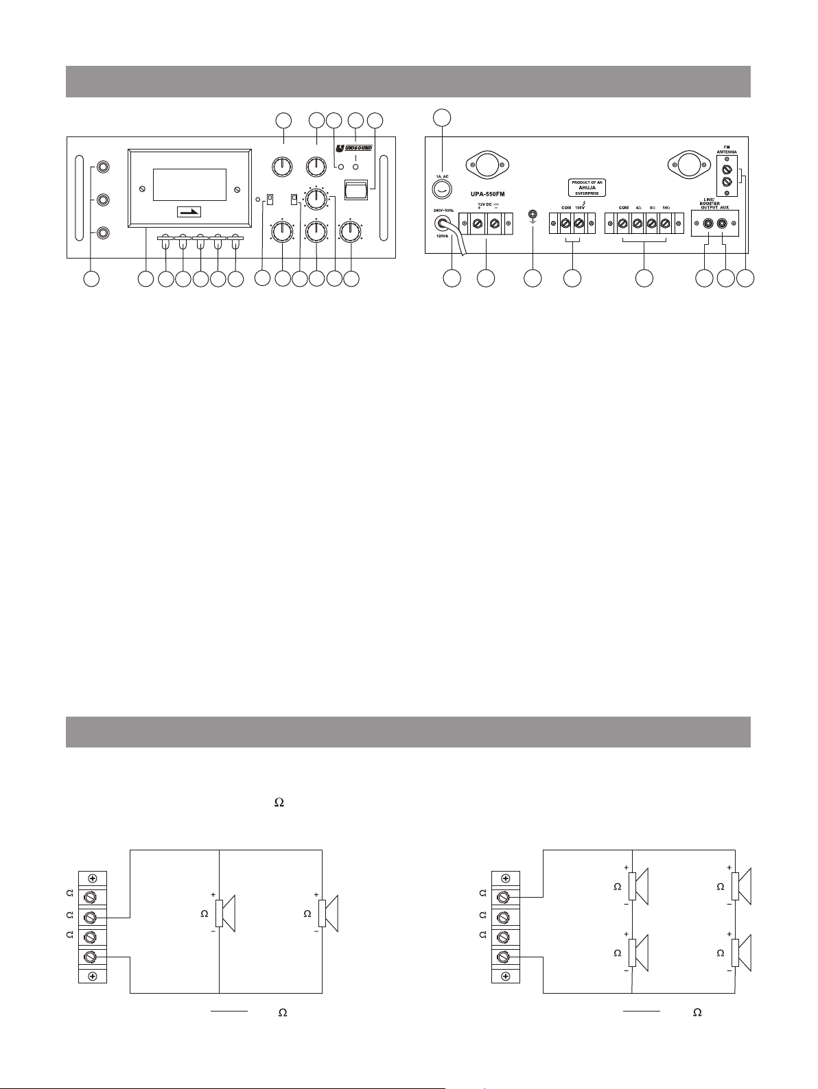
100VLine
When it is desired to connect speakers or driver units at a
distanceover50meters,itisrecommendedthatthe100Vline
output be used together with line matching transformer for
each speaker. This prevents excessive power loss in the
speakercables.
100VLine output is provided on a separate terminal strip with
its COM separate from low impedance speaker connections.
This provides facility for floating or grounding of long line
installations. For floating, disconnect the shorting link
betweenearthterminalandCOMof100VLineoutputstrip.
Since this is a front loading cassette player, the cassette is to
be loaded with the exposed tape portion facing down and the
fullreeloftapetowardstheleft.
100V
COM
30W
20W
10W
5W
40W
COM
1
L1
L2
30W
20W
10W
5W
40W
COM
2
L1
L2
30W
20W
10W
5W
40W
COM
9
L1
L2
USINGTHETONECONTROLS
TheBass andTreble controlsshould beindividually set tothe
desiredlevelasexplainedbelow.
BASS: This controls the tonal quality of low frequencies
producedbymusicalinstrumentslikeTabla/Drumetc.,andto
some extent male human voice. When this control is
advanced towards BOOST position, it will boost i.e. increase
the intensity of the low frequencies. Similarly, when it is
lowered towards CUT position, it will cut i.e. reduce the
intensityoflowfrequencies.
TREBLE: This controls the tonal quality of high frequencies
produced by musical instruments like Violin, Sarangi and
Sitar etc. and to some extent female human voice. When the
control is advanced towards BOOST position, it will boost i.e.
increase the intensity of high frequencies. Similarly, when
lowered, towards CUT position, it will cut i.e. reduce the
intensityofhighfrequencies.
FMRADIOOPERATION
PuttheFM/MIC-2SwitchinFMposition.
TunetothedesiredFMstationbyrotatingtheTuningKnob.
FM Antenna Screw Strip has been provided for optimizing the
receptionofthetunerbyconnectinganexternalantenna.
Incase ofstronglocalstations, or whentheequipmentis situated
near a transmitting station, the external antenna may not be
required. In case of fringe areas where the signal is very weak, a
diapoleantenna may beconnected to theantenna terminals with
thehelpof2-wayribbonwire.
PRECAUTION
1. Do not use this unit in high ambient temperature.
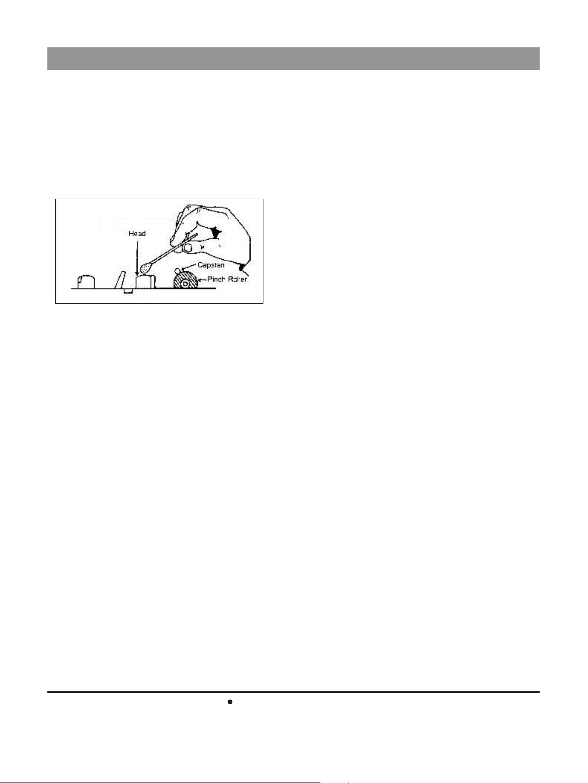
2. Before the cassette tape is inserted into the cassette slot,
loose tape must be tightened up to avoid its entangling with
thepinchroller.
3. Speaker impedance mismatch may cause insufficient output
oroverheatingofthecomponents,whichmayleadtofailureof
thecomponents. Check andmakesurethatthe impedance of
the speakers is equal to or greater than the selected
impedanceontheoutputterminalstrip.
4. Use of C-120 cassette is not recommended as it is extremely
thinandmaycauseproblems.