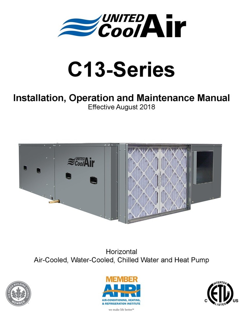
United CoolAir VertiCool Classic Series User manual

VertiCool™ CLASSIC
Engineering Guide
Effective August 2016
Air-Cooled, Water-Cooled,
Chilled Water and Water Source Heat Pump

Engineering Guide
VertiCool ™ Classic
2
Subject to change without notice. 20.10-TD (0816)
Product Features��������������������������������������������������������������������������������������������������� 3
UNIT FEATURES �������������������������������������������������������������������������������������������� 3
OPTIONS:������������������������������������������������������������������������������������������������������������������������������ 3
Physical Data����������������������������������������������������������������������������������������������������� 4–5
Air-Cooled Performance Data (a) (b) (c) ��������������������������������������������������������������� 6
Water-Cooled Performance Data (a) (c) (d) (e)����������������������������������������������������� 7
Water Source Heat Pump Performance Data (a) (c) (d) (e) ���������������������������������� 8
Blower Performance Data ������������������������������������������������������������������������������������� 9
Evaporator (a) (b) �������������������������������������������������������������������������������������������� 9
Condenser������������������������������������������������������������������������������������������������������� 9
Steam Coil������������������������������������������������������������������������������������������������������� 9
Hot Water Coil Performance (a) (b) (c) (d) (e) (f) (g) ������������������������������������������� 10
Chilled Water Coil Performance (a) (b) (c) (d) (e) (f) ������������������������������������������� 10
Electrical Data ����������������������������������������������������������������������������������������������������� 11
Cooling Only:������������������������������������������������������������������������������������������������� 11
Electrical Data ����������������������������������������������������������������������������������������������������� 12
Cooling Only:������������������������������������������������������������������������������������������������� 12
Electrical Data ����������������������������������������������������������������������������������������������������� 13
Cooling with Electric Heat: ���������������������������������������������������������������������������� 13
Electrical Data ����������������������������������������������������������������������������������������������������� 14
Compressor RLA Electrical Data:������������������������������������������������������������������ 14
Evaporator Motor FLA: ���������������������������������������������������������������������������������� 14
Condenser Motor FLA: ���������������������������������������������������������������������������������� 14
Electric Heat FLA: �������������������������������������������������������������������������������� 14
Electrical Data Air-Cooled (c) (d) (e)�������������������������������������������������������������������� 15
Electrical Data Air-Cooled (c) (d)������������������������������������������������������������������������� 16
Electrical Data Water-Cooled (c) (d) (e) �������������������������������������������������������������� 17
Electrical Data Water-Cooled (c) (d)�������������������������������������������������������������������� 18
Basic Unit Congurations ������������������������������������������������������������������������������������ 19
Basic Unit Dimensions����������������������������������������������������������������������������������������� 20
Cabinet Congurations and Unit Drawings���������������������������������������������������� 21–23
Service Clearance ����������������������������������������������������������������������������������������������� 24
Application Data �������������������������������������������������������������������������������������������������� 25
Miscellaneous Technical Data ����������������������������������������������������������������������������� 25
Shipment Congurations ������������������������������������������������������������������������������� 26–28
BASIC MODEL DESIGNATION��������������������������������������������������������������������������� 32
Contents

Engineering Guide
VertiCool ™ Classic
3
Subject to change without notice. 20.10-TD (0816)
UNIT FEATURES
• Air-Cooled, Water-Cooled, Chilled Water or Water Source Heat
Pump Congurations
• R-410a Refrigerant, Factory Charged
• 12 thru 30 Ton Units are Splittable using Resealable Refrigerant
Fittings
• Fits through 32” doorways
• ½” Fiberglass Lined Cabinet (Thermal/Acoustical, min� density of
2 Pounds)
• Rugged cabinet construction
• Duct Flanges Factory Installed
• Drain Connections on Both Evaporator and Condensing Sections
• 304 Stainless Steel “V” Style Drain Pan in Evaporator Section
• �25” ESP Capability (1” ESP Option for Evaporator and
Condensing Sections)
• Belt Driven Blowers (Evaporator and Condensing Sections)
• Ball Bearing Motors
• Resiliently Mounted Ball Bearings for Blowers
• Cast Iron Pulleys and Sheaves
• Variable Pitch Motor Sheaves
• All shafts, sheaves & pulleys keyed
• Adjustable Motor Mounts in Evaporator and Condensing Sections
• High (Manual Reset) and Low (Auto Reset) Refrigerant Pressure
Safety Switches
• Loss of Air Safety Switch (when electric heat used)
• Scroll Compressors
• Adjustable Expansion Valve with External Equalizer (MOP Type)
• Sight Glass / Moisture Indicators
• Filter Driers
• High and Low Side Schrader Access Fittings
• Draw Through Air Flow Conguration
• Interlaced Evaporator Coils
• Single Electrical Control Box
• 24 Volt Control Circuits
• Transformer with Built In Circuit Breaker
• Individual Contactor for each Stage of Electric Heat
• Individual Contactor for each Motor and Compressor
• Co-axial Counter Flow Heat Exchanger(s) on Water-Cooled Units
• Limited Warranty 1 Year on Parts and 5 Years on Compressors
• Functionally Run Tested at the Factory
Product Features
The VertiCool™ Classic Series of units are splittable,
self-contained, oor mounted, single package units.
They are available as air-cooled, water-cooled or as
water source heat pump congurations. The units offer
a variety of evaporator air ow patterns for application
exibility. Additionally, the units are available as standard
congurations or they can be tailored for a specic
application as a made-to-order unit�
OPTIONS: (Items underlined are factory installed):
• Powder Coated Cabinet
• Plenum w/ Discharge Grilles or Duct Flange
• Condensate Pump
• Electric Heat
• Protective Coil Coatings
• SCR Controllers
• Air or Water Side Economizer
• Hot Water, Chilled Water and Steam Coils
• Variable Frequency Drive (Evaporator)
• Drain Pan Overow Switch
• Head Pressure Control Valves
• Double Wall Construction (Solid or Perforated)
or Acoustic Foam Package
• Hot Gas Bypass (Standard or Modulating)
• Low Ambient Operation (VFD or Flooded
Condenser)
• Freezestat
• Non-Fused Disconnects
• Thermostats
• Marvel Microprocessor Controls
• Upgraded Motors / Drive Sets
• Compressor Anti-Short Cycle Timer
• Quench Valve w/ Suction Accumulator
• Suction Line Accumulator
• Oil Separator
• Liquid Receivers
• Hot Gas Reheat
• Condenser Filter Box
• Return Air Grilles
• Chilled Water and Hot Water Valves
• Smoke Detectors
• Firestats
• Dry Contacts
• Steam Canister Humidier
CONTACT THE FACTORY FOR OTHER
OPTIONAL FEATURES

Engineering Guide
VertiCool ™ Classic
4
Subject to change without notice. 20.10-TD (0816)
Physical Data
Notes:
(a) Requires optional motor / drive upgrade�
(b) Net operating weight is for basic unit only� Options will add weight�
(c) Refrigerant circuit components will impact unit performance�
(d) Pulley & Belt upgrade only�
(e) 575 volt available� Consult factory�
(f) Contact factory for geothermal applications�
(g) R-410a Refrigerant charge is for base unit conguration. Addition of some options may alter refrigerant amount
Tons 3 4 5 8 10
Evaporator Supply Air
CFM 1200 1600 2000 3200 4000
Std� ESP 0�25”
Max� ESP (a) 1�0”
Evaporator Blower Size 10 - 8
Qty 1 2
Evaporator Motors Std� HP ½ ¾ ¾ 1�5
Opt� HP ¾ 1 1 2
Evaporator Coil
Rows 4
Face Area 4�44 9
FPI 12
Filter
Type Pleated Throwaway
Qty 2 ½
Dimensions 20 x 20 x 2 16 x 25 x 2 / 20 x 25 x 2
Efciency MERV 8
Compressor Type Scroll
Qty 1 2
Condenser Air
CFM 2100 2800 3500 6000 7500
Std� ESP 0�25”
Max� ESP (a) 1�0”
Condenser Blower Size 10 - 8 15 - 9
Qty 2
Condenser Motors Std� HP ½ ¾ 1 2 3
Opt� HP ¾ 1 1�5 3 5
Condenser Coil
Rows 4
Face Area 6 11�25
FPI 14 12
Water Cooled Cond. (f) Type Co-axial
Qty 1 2
Weight (Net Operating) (b)
Air-Cooled 655 655 655 1150 1150
Water-Cooled 480 480 480 940 940
Water Source HP 505 505 505 1000 1000
Available Voltages (e)
208/230-1-60 • • •
208/230-3-60 • • • • •
460-3-60 • • • • •

Engineering Guide
VertiCool ™ Classic
5
Subject to change without notice. 20.10-TD (0816)
Physical Data
Notes:
(a) Requires optional motor / drive upgrade�
(b) Net operating weight is for basic unit only� Options will add weight�
(c) Refrigerant circuit components will impact unit performance�
(d) 575 volt available� Contact factory�
(e) Contact factory for geothermal applications�
(f) R-410a Refrigerant charge is base unit conguration. Addition of some options may alter refrigerant amount.
(g) Units always shipped split�
(h) Pulley & Belt upgrade only�
Tons 12 15 20 25 30 (g)
Evaporator Supply Air
CFM 4800 6000 8000 9770 12000
Std� ESP 0�25” 1�0”
Max� ESP (a) 1�0” 2�0”
Evaporator Blower Size 15-9 15 - 15
Qty 2
Evaporator Motors Std� HP 3 10
Opt� HP 5 15
Evaporator Coil
Rows 4
Face Area 13�33 17�8 22�6
FPI 10 12
Filter
Type Pleated Throwaway
Qty 4 8 4 / 4
Dimensions 20 x 24 x 2 16 x 20 x 2 20 x 20 x 2 / 20 x
25 x 2
Efciency MERV 8
Compressor Type Scroll
Qty 2
Condenser Air
CFM 7200 9000 12000 15000 16000
Std� ESP 0�25” 1�0”
Max� ESP (a) 1�0” 2�0”
Condenser Blower Size 15 - 9 18 - 18
Qty 3 2
Condenser Motors Std� HP 5 10 15
Opt� HP 5 (d) 7�5 7�5 15 15 (h)
Condenser Coil
Rows 4 6
Face Area 20 22�7
FPI 12
Water Cooled Cond. (e) Type Co-axial
Qty 2
Weight (Net Operating)
(b)
Air-Cooled 1895 1895 1945 1980 3400
Water-Cooled 1435 1435 1485 1520 2700
Water Source HP 1495 1495 1545 1580 3000
Available Voltages (d) 208/230-3-60 • • • • •
460-3-60 • • • • •

Engineering Guide
VertiCool ™ Classic
6
Subject to change without notice. 20.10-TD (0816)
Air-Cooled Performance Data (a) (b) (c)
Notes:
(a) Capacities are gross values, not adjusted for motor heat�
(b) Some refrigerant circuit components may impact on unit capacities�
(c) Applications with ambient conditions 75° F and lower may require additional refrigerant circuit components�
Consult factory for details�
Entering Air Temp. (°F) Entering Air Temperature (°F)
75 95 115
Tons CFM DB WB Total Sensible Total Sensible Total Sensible
VA3G*ASTA 1200
86 72 49530 32460 44430 30450 39570 28440
80 67 45720 31730 41090 29770 36570 27750
75 62�5 42250 31390 38020 29460 33800 27410
72 60 40370 30880 36350 28980 32310 26920
VA4G*ASTA 1600
86 72 59350 4400 53410 38020 47310 35580
80 67 54780 39490 49450 37130 43860 34610
75 62�5 51120 39170 46230 36740 41000 34110
72 60 49160 38580 44460 36120 39400 33410
VA5G*ASTA 2000
86 72 74040 49210 67700 46820 60370 43800
80 67 67610 48140 61740 45610 55220 42570
75 62�5 62820 47760 57260 45000 51300 41850
72 60 60490 47110 55050 44220 49330 41000
VA8G*ATA 3200
86 72 122010 81650 110080 76870 97240 72070
80 67 112840 80150 101810 75280 90110 70080
75 62�5 104520 79520 94180 74560 83340 69030
72 60 99940 78350 89920 73400 79490 67730
VA10G*ATA 4000
86 72 148100 98720 133100 93280 117790 87300
80 67 137410 97040 123950 91360 110360 85260
75 62�5 127200 96280 114900 90300 102590 84030
72 60 121400 94730 109670 88630 97980 82300
VA12G*ATA 4800
86 72 186390 119960 170190 113980 151910 107220
80 67 173180 118360 158140 111630 141850 104270
75 62�5 161770 117900 147580 110750 132730 103150
72 60 155570 116310 141760 109120 127580 101530
VA15G*ATA 6000
86 72 225520 143950 204470 135610 182760 126740
80 67 209910 141970 190830 133400 171330 124390
75 62�5 195180 141140 177540 132320 159660 123130
72 60 186910 139180 169990 130240 152900 120990
VA20G*ATA 8000
86 72 300680 192350 274770 181380 244950 168900
80 67 279060 189450 254000 177860 225690 164880
75 62�5 260010 188340 235590 176070 208400 162540
72 60 249800 185820 225630 173180 198960 159360
VA25G*ATA 10000
86 72 334060 216720 311970 207290 282980 194850
80 67 313120 214000 290510 203170 262260 189640
75 62�5 292590 213540 269940 201530 242520 187030
72 60 280950 211260 258300 198650 231330 183690
VA30G*ATA 12000
86 72 441490 294480 403140 279420 361840 262540
80 67 413100 290100 376410 274030 337790 256410
75 62�5 383920 287380 349040 270240 313000 251830
72 60 367140 282490 333340 264850 298770 246090

Engineering Guide
VertiCool ™ Classic
7
Subject to change without notice. 20.10-TD (0816)
Water-Cooled Performance Data (a) (c) (d) (e)
Notes:
(a) Capacities are gross values, not adjusted for motor heat�
(b) Pressure drop is for heat exchanger only and does not include piping, valves, ttings, etc.
(c) Some refrigerant circuit components may impact on unit capacities�
(d) Applications with water conditions 75° F and lower may require additional refrigerant circuit components�
Consult factory for details�
(e) Contact factory for geothermal applications�
PD
(Ft. H2O) (b)
Entering Air Temp. (°F) Entering Water Temperature (°F)
80 85 90
Tons GPM CFM DB WB Total Sensible Total Sensible Total Sensible
VW3G*ASTA 9 9�8 1200
86 72 50170 32820 48920 32290 47670 31770
80 67 46180 32010 45070 31480 43950 30970
75 62�5 42800 31690 41780 31170 40760 30660
72 60 41010 31230 40030 30720 39060 30220
VW4G*ASTA 12 14�7 1600
86 72 62130 41510 60600 40930 59030 40330
80 67 57730 40500 56270 39880 54780 39240
75 62�5 53560 40080 52170 39410 50763 38730
72 60 51250 39480 49900 38800 48530 38100
VW5G*ASTA 15 10�9 2000
86 72 78660 51540 75350 50110 73550 49350
80 67 71930 49950 68770 48430 67080 47620
75 62�5 67300 49560 64330 47950 62740 47110
72 60 63820 48270 62360 47440 60840 46580
VW8G*ATA 24 8�8 3200
86 72 125900 83930 122580 82710 119200 81460
80 67 116250 81660 113240 80380 110170 79070
75 62�5 107950 80730 105170 79370 102350 77980
72 60 103490 79550 100830 78140 98120 76700
VW10G*ATA 30 10�2 4000
86 72 157390 103200 153710 101620 149900 99970
80 67 152700 110740 140010 98180 136450 96550
75 62�5 132260 98100 129010 96520 125660 94890
72 60 126550 96420 123400 94850 120150 93220
VW12G*ATA 36 8�8 4800
86 72 194460 123580 189820 121710 185110 119810
80 67 178880 120820 174630 118890 170310 116940
75 62�5 166040 119950 162090 117950 158080 115930
72 60 159460 118550 155660 116530 151800 114470
VW15G*ATA 45 14�0 6000
86 72 236600 148890 230900 146700 224980 144460
80 67 215530 144944 210560 142770 205420 140550
75 62�5 199860 143670 195460 141510 190910 139300
72 60 192310 141970 188200 139820 183950 137620
VW20G*ATA 60 11�0 8000
86 72 309690 196820 302830 194000 295810 191120
80 67 287370 193460 280700 190450 273900 187390
75 62�5 128120 192490 261620 189300 255020 186070
72 60 257760 190230 251360 186960 244860 183630
VW25G*ATA 75 13�0 10000
86 72 361890 227730 355210 225000 348190 222160
80 67 332270 222840 326080 220020 319600 217100
75 62�5 308820 221240 303000 218330 296920 215310
72 60 297010 218600 294380 215630 285510 212570
VW30G*ATA 90 8�0 12000
86 72 462560 306240 455220 303160 440290 296510
80 67 425770 296320 417770 292700 401640 285040
75 62�5 397690 293530 389350 289460 372610 280970
72 60 384130 290540 375660 286270 358740 277380

Engineering Guide
VertiCool ™ Classic
8
Subject to change without notice. 20.10-TD (0816)
Notes:
(a) Capacities are gross values, not adjusted for motor heat�
(b) Pressure drop is for heat exchanger only and does not include piping, valves, ttings, etc.
(c) Some refrigerant circuit components may impact on unit capacities�
(d) Values at 70° F Entering Water Temperature�
(e) Contact factory for geothermal applications�
Water Source Heat Pump Performance Data (a) (c) (d) (e)
Tons GPM CFM
Entering Air Temp. (°F)
Heating Capacity
DB
VW3G*ATA 9 1200 70 50100
60 51100
VW4G*ATA 12 1600 70 62500
60 64000
VW5G*ATA 15 2000 70 78400
60 80100
VW8G*ATA 24 3200 70 94500
60 96500
VW10G*ATA 30 4000 70 116600
60 119100
VW12G*ATA 36 4800 70 136500
60 139400
VW15G*ATA 45 6000 70 178500
60 182300
VW20G*ATA 60 8000 70 225800
60 230700
VW25G*ATA 75 10000 70 275800
60 281800
VW30G*ATA 90 12000 70 358400
60 366200

Engineering Guide
VertiCool ™ Classic
9
Subject to change without notice. 20.10-TD (0816)
Notes:
(a) Blower performance of basic unit with 2”, MERV 8 pleated throwaway lter and wet coil 80 / 67 / 95 and “A” air path.
(b) Performance with nominal CFM. For other CFM or ESP contact the factory for your specic application.
(c) Pulley & Belt upgrade only�
Blower Performance Data
Evaporator (a) (b)
Condenser
Notes:
(a) Contact factory with steam pressure and operating parameters�
(b) Low pressure, less than 10 psig�
(c) Steam valves and components by others, eld installed
(d) Requires addition of optional discharge plenum for 12 thru 30 Ton units if steam coil is being used for reheat and air path is “A” or
“B” (top supply)�
Steam Coil
External Static Pressure (ESP)
Tons CFM ≤0.25” 0.25” to 1.0”
3 1200 0�33 0�5
4 1600 0�5 1�0
5 2000 1�0 1�5
8 3200 1�0 1�5
10 4000 2�0 3�1�5
12 4800 1�5 2
15 6000 2�0 3
20 8000 5 5 (c)
≤ 1.0” 1�0” to 2�0”
25 9770 7�5 10
30 12000 7�5 10
External Static Pressure (ESP)
Tons CFM ≤0.25” 0.25” to 1.0”
3 0�5 1�0
4 1�0 1�5
5 1�5 2�0 (@ 0�9” max)
8 4800 2 3
10 6000 5 5
12 7200 2 3
15 9000 3�0 5
20 12000 7�5 7�5 (c)
25 15000 15 15
≤ 1.0” 1�0” to 2�0”
30 16000 10 15

Engineering Guide
VertiCool ™ Classic
10
Subject to change without notice. 20.10-TD (0816)
Notes:
(a) Capacity based on 80° F DB / 67° F WB with 45° F EFT�
(b) Chilled water entering at 45° F�
(c) For other operating conditions or uid type, contact the factory for performance.
(d) Chilled Water Coil Valves are optional�
(e) Valves are spring return, On / Off operation only�
(f) Chilled Water Coil Valve Sizes:
Chilled Water Coil Performance (a) (b) (c) (d) (e) (f)
Tons CFM GPM PD Ft. H2O Total (MBH) Sensible (MBH)
3 1200 10 4�4 46900 33200
4 1600 12 6�1 57000 41700
5 2000 13 7�1 64700 49100
8 3200 19 19 5�0 75700
10 4000 24 24 8�0 90700
12 4800 30 30 5�5 114700
15 6000 35 35 7�0 135400
20 8000 45 45 5�0 180300
25 10000 62 62 7�5 230800
30 12000 72 72 8�0 276300
Tons Valve Size
8 1-1/4”
10 1-1/4”
12 1-1/2”
15 2”
20 2-1/2”
25 2-1/2”
30 2-1/2”
Hot Water Coil Performance (a) (b) (c) (d) (e) (f) (g)
Tons CFM GPM PD Ft. H2O Capacity (MBH)
31200 5 2.6 48900
41600 5.9 3.6 58000
52000 6.8 4.7 66200
8 3200 18�1 3�4 174000
10 4000 21�0 4�4 204400
12 4800 23�5 5�4 228500
15 6000 27�0 7�0 262500
20 8000 32�0 9�7 312400
25 9770 35�0 12�4 340700
30 12000 36�0 14�8 350500
Notes:
(a) Hot Water Coil Valves are optional�
(b) Valves are spring return, On / Off operation only�
(c) Entering water at 180° F� Leaving water at approximately 160° F�
(d) Entering air temperature 65° F�
(e) For other operating conditions or uid type, contact the factory for performance.
(f) Requires addition of optional discharge plenum for 12 thru 30 Ton units if hot water
coil is being used for reheat and air path is “A” or “B” (top supply)�
(g) Hot Water Coil Valve Sizes:
Tons Valve Size
8 3/4”
10 1”
12 1-1/4”
15 1-1/4”
20 1-1/4”
25 1-1/2”
30 Contact Factory

Engineering Guide
VertiCool ™ Classic
11
Subject to change without notice. 20.10-TD (0816)
Electrical Data
The following sections provides the formulas and the data to calculate the Minimum Circuit Ampacity (MCA) and the
Maximum Fuse Size (MOP) for your specic unit conguration.
There are a variety of unit congurations. Please make sure to use the correct formulas per your conguration.
It must be noted that the formulas refer to the largest motor amps� This typically is the compressor (RLA), but it can also
be one of the blower motors (FLA)�
The data provided will cover the majority of available unit congurations. However, it should be noted that additional
combinations may be available and the factory can be contacted for this data�
Examples have also been provided for each conguration.
RLA = Compressor Rated Load Amps
FLA = Full Load Amps (Used for Blower Motors and Electric Heaters)
MCA = Minimum Circuit Ampacity (Calculated value)
MOP = Maximum Fuse Size (Calculated value)
Cooling Only:
Package Unit
NOTE: Largest motor amps may not always be the compressor�
MCA = (1�25 x largest motor amps) + the sum of the remaining motors
MOP = (2�25 x largest motor amps) + the sum of remaining motors
Condensing Section w/ Compressor(s)
NOTE: Largest motor amps may not always be the compressor�
MCA = (1�25 x largest motor amps) + the sum of the remaining motors
MOP = (2�25 x largest motor amps) + the sum of remaining motors
Evaporator Only Section
MCA = (1�25 x Evap� Blower Motor Amps)
MOP = (2�25 x Evap� Blower Motor Amps)
Condenser Only Section w/o Compressor(s)
MCA = (1�25 x Cond� Blower Motor Amps)
MOP = (2�25 x Cond� Blower Motor Amps)
Evaporator Section w/ Compressor(s)
NOTE: Largest motor amps may not always be the compressor�
MCA = (1�25 x largest motor amps) + the sum of the remaining motors
MOP = (2�25 x largest motor amps) + the sum of remaining motors

Engineering Guide
VertiCool ™ Classic
12
Subject to change without notice. 20.10-TD (0816)
Electrical Data
Examples
Cooling Only:
Package Unit
NOTE: Largest motor amps may not always be the compressor�
MCA = (1�25 x largest motor amps) + the sum of the remaining motors
MOP = (2�25 x largest motor amps) + the sum of remaining motors
Dual Compressors RLA = 19�2 each
Evap� Blower Motor FLA = 4�8
Cond� Blower Motor FLA = 9�2
MCA = (1�25 x 19�2) + 19�2 + 4�8 + 9�2 = 57�2
MOP = (2�25 x 19�2) + 19�2 + 4�8 + 9�2 = 76�4
Rounded Down to 75
Condensing Section w/ Compressor(s)
NOTE: Largest motor amps may not always be the compressor�
MCA = (1�25 x largest motor amps) + the sum of the remaining motors
MOP = (2�25 x largest motor amps) + the sum of remaining motors
Dual Compressors RLA = 19�2 each
Cond� Blower Motor FLA = 13�6
MCA = (1�25 x 19�2) + 19�2 + 13�6 = 56�8
MOP = (2�25 x 19�2) + 19�2 + 13�6 = 76
Rounded Down to 75
Evaporator Only Section
MCA = (1�25 x Evap� Blower Motor Amps)
MOP = (2�25 x Evap� Blower Motor Amps)
Evap� Blower Motor FLA = 4�8
MCA = (1�25 x 4�8) = 6�0
MOP = (2�25 x 4�8) = 10�8
Rounded Down to 10
Condenser Only Section w/o Compressor(s)
MCA = (1�25 x Cond� Blower Motor Amps)
MOP = (2�25 x Cond� Blower Motor Amps)
Cond� Blower Motor FLA = 9�2
MCA = (1�25 x 9�2) = 11�5
MOP = (2�25 x 9�2) = 20�7
Rounded Down to 20
Evaporator Section w/ Compressor(s)
NOTE: Largest motor amps may not always be the compressor�
MCA = (1�25 x largest motor amps) + the sum of the remaining motors
MOP = (2�25 x largest motor amps) + the sum of remaining motors
Dual Compressors RLA = 23�2 each
Evap� Blower Motor FLA = 13�6
MCA = (1�25 x 23�2) + 23�2 + 13�6 = 65�8
MOP = (2�25 x 23�2) + 23�2 + 13�6 = 89
Rounded Down to 85

Engineering Guide
VertiCool ™ Classic
13
Subject to change without notice. 20.10-TD (0816)
Electrical Data
Cooling with Electric Heat:
Package Unit
NOTE: Largest motor amps may not always be the compressor�
Electric Heat
On equipment with multiple modes of operation (i�e� cooling or heating), each mode
shall be evaluated and whichever load condition provides the highest value shall be used�
Use the larger of the following:
MCA = (1�25 x largest motor amps) + the sum of the remaining motors
or MCA = (Heater FLA + Evap� Motor FLA) x 1�25
MOP = (2�25 x largest motor amps) + the sum of the remaining motors
or MOP = (Evap� Blower Motor x 2�25) + Heater Amps
Evaporator Only Section
Electric Heat
MCA = (Heater FLA + Evap� Motor FLA) x 1�25
MOP = (Evap� Blower Motor x 2�25) + Heater Amps
Evaporator Section w/ Compressor(s) - - Same as Package Unit above
Condensing Section w/ Compressor(s) or Condenser Only Section w/o Compressor(s)
same as Cooling Only models
Examples
Cooling with Electric Heat:
Single Package
NOTE: Largest motor amps may not always be the compressor�
Electric Heat
Use the larger of the following:
MCA = (1�25 x 19�2) + 19�2 + 6�6 + 6�8 = 57�2
or MCA = (41�2 + 4�8) x 1�25 = 57�5 Use this value
MOP = (2�25 x 19�2) + 19�2 + 4�8 + 9�2 = 76�4 Use this value Rounded Down to 75
or MOP = (4�8 x 2�25) + 41�2 = 52
Evaporator Only Section
Electric Heat
MCA = (41�2 + 4�8) x 1�25 = 57�5
MOP = (4�8 x 2�25) + 41�2 = 52 MOP can’t be lower than MCA Rounded Up to 60
Evaporator Section w/ Compressor(s) - - Same as Single Package above

Engineering Guide
VertiCool ™ Classic
14
Subject to change without notice. 20.10-TD (0816)
Electrical Data
Compressor RLA Electrical Data:
Tons Compressor (Qty) 208/230-3-60 460-3-60
3 1 13�5 6�0
4 1 14�5 6�3
5 1 19�2 8�7
8 2 14�5 ea� 6�3 ea�
10 2 19�2 ea� 8�7 ea�
12 2 23�2 ea� 11�2 ea�
15 2 29�5 ea� 14�7 ea�
20 2 33�3 ea� 17�9 ea�
25 2 48�1 ea� 18�6 ea�
30 2 55�8 ea� 26�9 ea�
Evaporator Motor FLA:
HP Used In Tons 208/230-3-60 460-3-60
0�33 3�0 1�6 0�8
0�5 3�8 2�2 1�0
0�75 5�8 3�2 1�5
1�0 7�0 3�4 1�6
1�5 9�4 4�8 2�4
2 11�3 6�2 3�1
3 17.5 9.2 4.3
5 - 13.6 6.3
7.5 - 21.0 9.6
10 - 27.0 12.5
15 - 40.6 18.5
Condenser Motor FLA:
HP Used In Tons 208/230-3-60 460-3-60
0�5 3�8 2�2 1�0
0�75 5�8 3�2 1�5
1 7�0 3�4 1�6
1�5 9�4 4�8 2�4
2 11�3 6�2 3�1
3 17�5 9�2 4�3
5 - 13�6 6�3
7�5 - 21�0 9�6
10 - 27�0 12�5
15 - 40�6 18�5
Electric Heat FLA: (Heaters nominally rated at 220 or 277 volts� Amps listed at 208, 230 and 460 volts)
Nom. kW Stages Used In Tons 208-3-60 230-3-60 460-3-60
5 1 3, 4 22�7 13�1 6�3
10 1 or 2 8 45�5 26�2 12�6
15 1 or 2 8, 10, 12 - 39�4 18�8
20 (a) 2 8, 10, 12, 15, 20 - 52�5 25�1
25 (a) 2 8, 10, 12, 15, 20, 25, 30 - 65�6 31�4
30 (a) 2 10, 12, 15, 20, 25, 30 - 78�7 37�7
45 (a) 2 15, 20, 25, 30 - 118.1 56.5
Notes:
(a) If electric heater will be used as reheat in a 12 thru 30 Ton unit and the air path is “A” or “B” (top supply), an optional discharge air
plenum is required
Contact factory for 575 volt data�

Engineering Guide
VertiCool ™ Classic
15
Subject to change without notice. 20.10-TD (0816)
Notes:
(a) Electric heaters nominally rated at 220 or 277 volts� Amps listed at 230 or 460 volts�
(b) Electric heaters listed being used for heat�
(c) Use Copper Conductors Only�
(d) Values listed are typical and may vary dependent upon components utilized�
(e) All unit electrical capabilities not shown. Contact factory for specic unit combinations.
Electrical Data Air-Cooled (c) (d) (e)
Tons Voltage
Compressor
RLA
Evaporator Motor Condenser Motor Electrical Heat (a) (b)
MCA MOPHP FLA HP FLA Nom. KW Amps
VA3G*ASTA
208/230-
3-60 13�5
460-3-60 6
VA4G*ASTA
208/230-
3-60 14�5
460-3-60 6�3
VA5G*ASTA
208/230-
3-60 19�2
460-3-60 8�7
VA8G*ATA
208/230-
3-60 14�5 ea�
1�5 4�8 2 6�2 - - - - - - 43�6 55
2 6�2 3 9�2 - - - - - - 48�0 60
1�5 4�8 2 6�2 10 27�4 43�6 55
2 6�2 3 9�2 25 68�6 93�5 95
460-3-60 6�3 ea�
1�5 2�4 2 3�1 - - - - - - 19�7 25
2 3�1 3 4�3 - - - - - - 21�6 25
1�5 2�4 2 3�1 10 11�5 19�7 25
2 3�1 3 4�3 25 28�8 39�9 40
VA10G*ATA
208/230-
3-60 19�2 ea�
1�5 4�8 3 9�2 - - - - - - 57�2 75
2 6�2 5 13�6 - - - - - - 63�0 80
1�5 4�8 3 9�2 15 41�2 57�5 75
2 6�2 5 13�6 30 82�3 110�6 115
460-3-60 8�7 ea�
1�5 2�4 3 4�3 - - - - - - 26�3 30
2 3�1 5 6�3 - - - - - - 29�0 35
1�5 2�4 3 4�3 15 17�3 26�3 30
2 3�1 5 6�3 30 34�6 47�1 50

Engineering Guide
VertiCool ™ Classic
16
Subject to change without notice. 20.10-TD (0816)
Electrical Data Air-Cooled (c) (d)
Notes:
(a) Electric heaters nominally rated at 220, 460 or 575 volts� Amps listed at 220, 460 or 575 volts�
(b) Electric heaters listed being used for heat�
(c) Use Copper Conductors Only�
(d) Values listed are typical and may vary dependent upon components utilized�
Tons Voltage
Compressor
RLA
Evaporator Motor Condenser Motor Electrical Heat (a) (b)
MCA MOPHP FLA HP FLA Nom. KW Amps
12
208/230-
3-60 23�2 ea�
3 9�2 5 13�6 - - - - - - 75�0 95
5 13�6 5 13�6 - - - - - - 79�4 100
3 9�2 5 13�6 15 41�2 75�0 95
5 13�6 5 13�6 30 82�3 119�9 120
460-3-60 11�2 ea�
3 4�3 5 6�3 - - - - - - 35�8 45
5 6�3 5 6�3 - - - - - - 37�8 45
3 4�3 5 6�3 15 17�3 35�8 45
5 6�3 5 6�3 30 34�6 51�1 55
15
208/230-
3-60 29�5 ea�
3 9�2 5 13�6 - - - - - - 89�2 115
5 13�6 7�5 21�0 - - - - - - 101�0 130
3 9�2 5 13�6 20 54�8 89�2 115
5 13�6 7�5 21�0 45 123�5 171�4 175
460-3-60 14�7 ea�
3 4�3 5 6�3 - - - - - - 43�7 55
5 6�3 7�5 9�6 - - - - - - 49�0 60
3 4�3 5 6�3 20 23�0 43�7 55
5 6�3 7�5 9�6 45 51�9 72�8 75
20
208/230-
3-60 33�3 ea�
3 9�2 5 13�6 - - - - - - 97�7 130
5 13�6 7�5 21�0 - - - - - - 109�5 140
3 9�2 5 13�6 20 54�8 97�7 130
5 13�6 7�5 21�0 45 123�5 171�4 175
460-3-60 17�9 ea�
3 4�3 5 6�3 - - - - - - 50�9 65
5 6�3 7�5 9�6 - - - - - - 56�2 70
3 4�3 5 6�3 20 23�0 50�9 65
5 6�3 7�5 9�6 45 51�9 72�8 75
25
208/230-
3-60 48�1 ea�
10 27�0 10 27�0 - - - - - - 162�2 210
15 40�6 15 40�6 - - - - - - 189�4 235
10 27�0 10 27�0 25 68�6 162�2 210
15 40�6 15 40�6 45 123�5 205�1 235
460-3-60 18�6 ea�
10 12�5 10 12�5 - - - - - - 66�9 85
15 18�5 15 18�5 - - - - - - 78�9 95
10 12�5 10 12�5 25 28�8 66�9 85
15 18�5 15 18�5 45 51�9 88�0 95
30
208/230-
3-60 55�8 ea�
10 27�0 15 40�6 - - - - - - 193�2 245
15 40�6 15 40�6 - - - - - - 206�8 260
10 27�0 15 40�6 25 68�6 193�2 245
15 40�6 15 40�6 45 123�5 206�8 260
460-3-60 26�9 ea�
10 12�5 15 18�5 - - - - - - 91�5 115
15 18�5 15 18�5 - - - - - - 97�5 120
10 12�5 15 18�5 25 28�8 91�5 115
15 18�5 15 18�5 45 51�9 97�5 120

Engineering Guide
VertiCool ™ Classic
17
Subject to change without notice. 20.10-TD (0816)
(a) Electric heaters nominally rated at 220, 460 or 575 volts� Amps listed at 220, 460 or 575 volts�
(b) Electric heaters listed being used for heat�
(c) Use Copper Conductors Only�
(d) Values listed are typical and may vary dependent upon components utilized�
(e) All unit electrical capabilities not shown. Contact factory for specic unit combinations.
Electrical Data Water-Cooled (c) (d) (e)
Tons Voltage
Compressor
RLA
Evaporator Motor Electrical Heat (a) (b)
MCA MOPHP FLA Nom. KW Amps
3
4
5
8
208/230-3-60 14�5 ea�
1�5 4�8 - - - - - - 37�4 50
2 6�2 - - - - - - 38�8 50
1�5 4�8 10 27�4 40�3 50
2 6�2 25 68�6 93�5 95
460-3-60 6�3 ea�
1�5 2�4 - - - - - - 16�6 20
23�1 - - - - - - 17�3 20
1�5 2�4 10 11�5 17�4 20
2 3�1 25 28�8 39�9 40
10
208/230-3-60 19�2 ea�
1�5 4�8 - - - - - - 48�0 65
2 6�2 - - - - - - 49�4 65
1�5 4�8 15 41�2 57�5 65
2 6�2 30 82�3 110�6 115
460-3-60 8�7 ea�
1�5 2�4 - - - - - - 22�0 30
2 3�1 - - - - - - 22�7 30
1�5 2�4 15 17�3 24�6 30
2 3�1 30 34�6 47�1 50

Engineering Guide
VertiCool ™ Classic
18
Subject to change without notice. 20.10-TD (0816)
(a) Electric heaters nominally rated at 220, 460 or 575 volts� Amps listed at 220, 460 or 575 volts�
(b) Electric heaters listed being used for heat�
(c) Use Copper Conductors Only�
(d) Values listed are typical and may vary dependent upon components utilized�
(e) All unit electrical capabilities not shown. Contact factory for specic unit combinations.
Electrical Data Water-Cooled (c) (d)
Tons Voltage
Compressor
RLA
Evaporator Motor Electrical Heat (a) (b)
MCA MOPHP FLA Nom. KW Amps
12
208/230-3-60 23�2 ea�
3 9�2 - - - - - - 61�4 80
5 13�6 - - - - - - 65�8 85
3 9�2 15 41�2 63�0 80
5 13�6 30 82�3 119�9 120
460-3-60 11�2 ea�
3 4�3 - - - - - - 29�5 40
5 6�3 - - - - - - 31�5 40
3 4�3 15 17�3 29�5 40
5 6�3 30 34�6 51�1 55
15
208/230-3-60 29�5 ea�
3 9�2 - - - - - - 75�6 105
5 13�6 - - - - - - 80�0 105
3 9�2 20 54�8 80�0 105
5 13�6 45 123�5 171�4 105
460-3-60 14�7 ea�
3 4�3 - - - - - - 37�4 50
5 6�3 - - - - - - 39�4 50
3 4�3 20 23�0 37�4 50
5 6�3 45 51�9 72�8 75
20
208/230-3-60 33�3 ea�
3 9�2 - - - - - - 84�1 115
5 13�6 - - - - - - 88�5 120
3 9�2 20 54�8 84�1 115
5 13�6 45 123�5 171�4 175
460-3-60 17�9 ea�
3 4�3 - - - - - - 44�6 60
5 6�3 - - - - - - 46�6 60
3 4�3 20 23�0 44�6 60
5 6�3 45 51�9 72�8 75
25
208/230-3-60 48�1 ea�
10 27�0 - - - - - - 135�2 180
15 40�6 - - - - - - 148�8 195
10 27�0 25 68�6 135�2 180
15 40�6 45 123�5 205�1 215
460-3-60 18�6 ea�
10 12�5 - - - - - - 54�4 70
15 18�5 - - - - - - 60�4 75
10 12�5 25 28�8 54�4 70
15 18�5 45 51�9 88�0 95
30
208/230-3-60 55�8 ea�
10 27�0 - - - - - - 152�6 205
15 40�6 - - - - - - 166�2 220
10 27�0 25 68�6 152�6 205
15 40�6 45 123�5 205�1 220
460-3-60 26�9 ea�
10 12�5 - - - - - - 73�0 95
15 18�5 - - - - - - 79�0 105
10 12�5 25 28�8 73�0 95
15 18�5 45 51�9 88�0 105

Engineering Guide
VertiCool ™ Classic
19
Subject to change without notice. 20.10-TD (0816)
Basic Unit Congurations

Engineering Guide
VertiCool ™ Classic
20
Subject to change without notice. 20.10-TD (0816)
Basic Unit Dimensions
For specic unit dimensions, please visit our website at www.unitedcoolair.com/classic-drawings
or click here if you are viewing this document electronically�
TONS A B C D E F G
3, 4, 5 64 ½44 29 12
8 & 10 73 ⅝ 62 32 12 27 ⅞45 ¾5
12 & 15 79 ¼88 ¼32 ¼12 28 ¼51 4
20 & 25 87 ¼88 ¼32 ¼12 36 ¼51 5
30 98 ⅛96 ¼42 7⁄32 24 42 1⁄16 56 1⁄16 6
Table of contents
Other United CoolAir Heat Pump manuals
Popular Heat Pump manuals by other brands

ClimateMaster
ClimateMaster TRC09 Series Installation operation & maintenance

Daikin
Daikin EBLA09DAV3 User reference guide

Sharp
Sharp Plasmacluster AE-Z40KR Service manual

Daikin
Daikin ERSQ 011AAV1 Service manual

CIAT
CIAT YUNA II installation manual

System air
System air DVCompact Series Operation and maintenance instructions

SolarEast
SolarEast BLN-006TB1 Service manual

Daikin
Daikin RTSQ20PY1 Service manual

Mitsubishi Electric
Mitsubishi Electric EHST20C-VM2C.UK Service manual

Hoshizaki
Hoshizaki URC-6A parts list

Carrier
Carrier Weathermaster III 38HQ Installation, Start-Up and Service Instructions

Sinclair
Sinclair S-THERM+ SHP-140IRC Operation manual