RECOMMENDED PRACTICES AND WARNINGS
United Electric Controls Company recommends careful consideration of the following
factors when specifying and installing UE pressure and temperature units. Before
installing a unit, the Installation and Maintenance instructions provided with unit must
be read and understood.
• To avoid damaging unit, proof pressure and max temperature limits stated in lit-
erature and on nameplates must never be exceeded, even by surges in the system.
Operation of the unit up to proof pressure or max temperature is acceptable on a lim-
ited basis (i.e.start-up, testing) but continuous operation must be restricted to the des-
ignated adjustable range. Excessive cycling at proof pressure or maximum tempera-
ture limits could reduce sensor life.
• A back-up unit is necessary for applications where damage to a primary unit
could endanger life, limb or property. A high or low limit switch is necessary for appli-
cations where dangerous runaway condition could result.
• The adjustable range must be selected so that incorrect, inadvertent or mali-
cious setting at any range point can not result in an unsafe system condition.
• Install unit where shock, vibration and ambient temperature fluctuations will not
damage unit or affect operation. Orient unit so that moisture does not enter the enclo -
sure via the electrical connection.
• Unit must not be altered or modified after shipment. Consult UE if modification is
necessary.
• Monitor operation to observe warning signs of possible damage
to unit, such as drift in set point. Check unit immediately.
• Preventative maintenance and periodic testing is necessary for critical applica -
tions where damage could endanger property or personnel.
• For all applications, a factory set unit should be tested before use.
• Electrical ratings stated in literature and on nameplate must not be exceeded.
Overload on a switch can cause damage, even on the first cycle. Wire unit according
to local and national electrical codes, using wire size recommended in installation
sheet.
• Use only factory authorized replacement parts and procedures.
• Do not mount unit in ambient temp. exceeding published limits.
• For remote mounted temperature units, capillary lengths beyond 10 feet can
increase chance of error, and may require re-calibration of set point and indication.
LIMITED WARRANTY
UE warrants that the product thereby purchased is, upon delivery, free from defects
in material and workmanship and that any such product which is found to be defec-
tive in such workmanship or material will be repaired or replaced by UE (F.O.B. UE);
provided, however, that this warranty applies only to equipment found to be so defec-
tive within a period of 12 months after installation by buyer but not to exceed 18
months after delivery by the seller. Except for the limited warranty of repair and
replacement stated above, UE disclaims all warranties whatsoever with
respect to the product, including all implied warranties of merchantability or fit-
ness for any particular purpose.
LIABILITY LIMITATION
The sole and exclusive remedy of buyer for any liability or seller
for any claim, including incurred in connection with (I) breach of any warranty whatso -
ever expressed or implied, (II) a breach of contract, (III) a negligent act or acts (or
negligent failure to act) committed by seller, or (IV) an act for which strict liability will
be imputed to seller, is limited to the limited warranty or repair and replacement stat-
ed herein. In no event shall the seller be liable for any special,
indirect, consequential or other damages of a like general nature, including,
without limitation, loss of profits or production, or loss or expenses of any
nature incurred by any third party.
180 Dexter Ave., P.O. Box 9143, Watertown, MA 02272-9143 USA 617 926-1000
Fax 617 926-2568
IKON5M8/97
UNITED ELECTRIC
CONTROLS
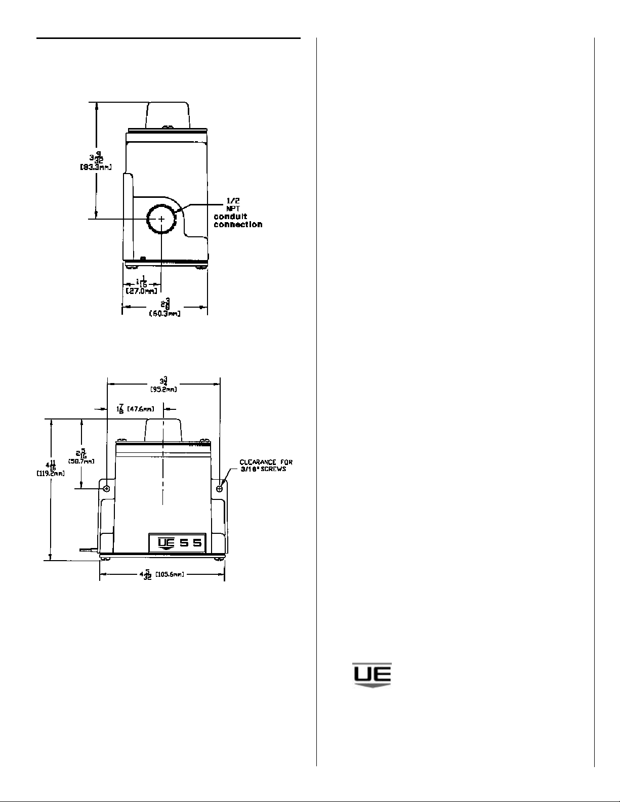
Dimensions