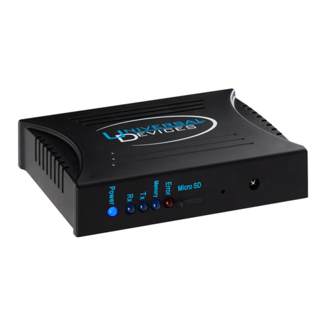
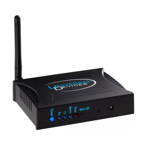
Universal Devices ISY-26 User manual

ISY – 26
Home Automation Controller
USER GUIDE

- 2 -
Table of Content
1. Purpose ....................................................................................................................... 5
2. Theory of Operation ................................................................................................... 5
3. Installation and Configuration.................................................................................... 6
3.1 Installation........................................................................................................... 6
3.2 Prerequisites ........................................................................................................ 6
3.3 Host Co puter Configuration............................................................................. 6
4. Additional Hardware Required .................................................................................. 7
5. Starting the GUI on a Host Co puter........................................................................ 8
6. Main GUI Co ponents ............................................................................................ 10
6.1 Top Pane............................................................................................................ 10
6.2 Navigation Pane or Tree View .......................................................................... 10
6.3 View Pane ......................................................................................................... 11
6.4 Botto Pane ...................................................................................................... 11
7. Top Pane - Menu ...................................................................................................... 12
7.1 File Menu .......................................................................................................... 12
7.2 Link Manage ent Menu ................................................................................... 13
7.3 Tools Menu ....................................................................................................... 14
7.4 Help Menu......................................................................................................... 15
8 Top Pane – Tool Bar ................................................................................................ 17
8.1 Expand All......................................................................................................... 17
8.2 Collapse All....................................................................................................... 17
8.3 Sort .................................................................................................................... 17
8.4 New Scene......................................................................................................... 17
8.5 Start Linking...................................................................................................... 18
8.6 Floor Plan .......................................................................................................... 18
8.7 Trend (Chart)..................................................................................................... 19
9. Left Pane – Configuration........................................................................................ 19
9.1 Location Configuration ..................................................................................... 20
9.2 Date and Ti e Configuration............................................................................ 20
9.3 Messaging Configuration .................................................................................. 20
9.4 Notifications Settings ........................................................................................ 21
10. Left Pane – Schedules ........................................................................................... 22
10.1 New Schedule.................................................................................................... 22
10.2 Adding a Schedule for a Specific Ti e ............................................................ 23
10.3 Adding a Schedule for Everyday at a Given Ti e............................................ 24
10.4 Adding a Repeated Schedule for Everyday....................................................... 24
10.5 Adding a Schedule for Certain Days of the Week ............................................ 24
10.6 Holding Schedules on a Certain Date ............................................................... 24
10.7 Holding Schedules for a Duration..................................................................... 25
10.8 Editing an Existing Schedule ............................................................................ 25
10.9 Re oving a Schedule........................................................................................ 25
11. Left Pane – Triggers.............................................................................................. 26
11.1 Setting a Trigger................................................................................................ 26
11.2 Re oving a Trigger .......................................................................................... 27
11.3 Pending Notifications........................................................................................ 27

- 3 -
11.4 Refresh .............................................................................................................. 27
12. Left Pane – ISY ................................................................................................... 28
12.2 Controller Icon .................................................................................................. 28
12.2 Query................................................................................................................. 28
12.3 Rena e.............................................................................................................. 28
12.4 Start Linking...................................................................................................... 28
13. Scenes.................................................................................................................... 29
13.1 Left Pane - Scene Menu .................................................................................... 29
13.2 Scenes................................................................................................................ 29
14. Device Properties .................................................................................................. 31
15. Errors and Error Messages .................................................................................. 33
15.1 Possible Errors................................................................................................... 33
15.2 To Report a New Error...................................................................................... 34
16. Supported Devices................................................................................................. 35
16.1 Insteon enabled devices..................................................................................... 35
16.2 Non Insteon enabled devices:............................................................................ 35
17. Registration ........................................................................................................... 36

- 4 -
Table of Figures
Figure 1– UPnP Configuration............................................................................................ 7
Figure 2– Network neighborhood/My Network Places ...................................................... 8
Figure 3 – Initial Browser ................................................................................................... 9
Figure 4– ID & Password.................................................................................................... 9
Figure 5– Main GUI Co ponents..................................................................................... 10
Figure 6– File Menu.......................................................................................................... 12
Figure 7– Link Manage ent Menu................................................................................... 13
Figure 8– Tools Menu ....................................................................................................... 14
Figure 9– Help Menu ........................................................................................................ 15
Figure 10– Expand All ...................................................................................................... 17
Figure 11– Collapse All .................................................................................................... 17
Figure 12- Sort .................................................................................................................. 17
Figure 13– New Scene ...................................................................................................... 18
Figure 14– Start Linking ................................................................................................... 18
Figure 15– Stop Linking ................................................................................................... 18
Figure 16– Floor Plan........................................................................................................ 19
Figure 17– Trend (Chart) .................................................................................................. 19
Figure 18– Configuration View ........................................................................................ 19
Figure 19– Notifications Settings...................................................................................... 21
Figure 20– Schedules View .............................................................................................. 22
Figure 21- Schedule Configurator..................................................................................... 23
Figure 22– Triggers........................................................................................................... 26
Figure 23– Controller Icon................................................................................................ 28
Figure 24– Fa ily Roo -Movie Scene ............................................................................ 30
Figure 25– Scene Properties.............................................................................................. 31
Figure 26– Connectivity Lost............................................................................................ 33

- 5 -
1. Purpose
The purpose of this docu ent is to guide the syste ’s installer with the steps
necessary to install and configure the Universal Devices’ ISY syste and operate
the GUI.
ISY co es configured for co unications with the device(s) of your choice. The
package contains:
i. Power supply
ii. Ethernet cable (Blue Cable)
iii. A Serial/RS232 cable – for advanced ad inistrative tasks. If you
would like to view syste status using Windows Hyper-ter inal or
any other ter inal e ulation software
iv. Docu entation and Utilities disk
v. Quick setup guide
2. Theor of Operation
All ISY syste s are e powered with UPnP (Universal Plug & Play) stack
through utilization of which all the devices on the network can sea lessly
co unicate with each other and other co puters on the network. ISY syste s
co e e bedded with their own browser based GUI and, as such, there is no need
for any software installation besides the nor al Java runti e and, optionally,
Excel for trending and reporting.
UPnP enables the devices on the network to auto atically show up as resources
on the “Network Neighborhood” or “My Network Places” on host co puters just
like a shared printer. For UPnP to work, the devices (and specifically ISY
syste s) need to be able to advertise their presence on the network and,
further ore, be able to co unicate their state changes to the network. In this
respect, then, the ain prerequisites for successful operations are
i. Network enabled environ ent
ii. Configuration of firewall progra s (besides Windows Firewall) to allow
for the devices to co unicate with the host syste beyond the local
network

- 6 -
3. Installation and Configuration
Configuration is required only if ISY does not show up auto atically.
3.1 Installation
Please perfor the following steps before plugging the ISY into power:
i. Connect the Ethernet cable to ISY and to your network hub. Note: the
network ust be DHCP enabled. If your DHCP is not enabled, please
consult ISY Installation and Configuration Guide on the acco panying
CD
ii. Connect the Serial co unications cable, provided with your Insteon
PLM (sold separately), to the connector arked Port A on the ISY and to
your co puter.
Plug in the power supply into ISY and then into a power outlet.
3.2 Prerequisites
3.2.1 Host Computer Software
i. Windows XP (for other versions of Windows, a separate guide is
provided)
ii. Internet Explorer 6 and above
iii. Java 1.5 (JRE 1.5) – included in the setup disk
iv. Microsoft Excel, for trending and charts
3.2.2 Network
ii. DHCP enabled network
iii. Ethernet topology
3.3 Host Computer Configuration
Configuration is co prised of three very easy steps:
i. UPnP Configuration
ii. Java Installation

- 7 -
3.3.1 UPnP Configuration
UPnP is nor ally disabled on all co puters by default. In order to ake sure
and/or to configure UPnP, please follow the following steps (refer to Figure 1):
i. Click on M Network Places (either on the Start Menu or Desktop)
ii. On the left Navigation Pane
a. If you see “Hide icons for networked UPnP devices”, you are done.
No further action is necessary
b. If you see “Show icons for networked UPnP devices”, click on it
and let the syste get configured. You are done.
Figure 1– UPnP Configuration
3.3.2 ava Installation
If you already have JRE 1.5v.6 installed, then no further action is necessary.
Otherwise, click on the jre/jdk-1_5_0_11-windows-i586-p.exe on the installation
CD to install JRE.
4. Additional Hardware Required
Please purchase and plug in the S artHo e PLM Version 4.6 in port A of the ISY.

- 8 -
5. Starting the GUI on a Host Computer
If you already have Java installed and UPnP enabled, all you have to do is to click on the
icon M Lighting (refer to Figure 1) appearing in the M Network Places (refer to
Figure 2) either on the Start Menu or Desktop.
If the “My Lighting” icon did not show up on your M Network Places you will need to
follow the configuration steps below.
Configuration is co prised of three very easy steps:
iii. UPnP Configuration
iv. Java Installation
v. If you have any other network firewall software, please contact us to walk you
through the configuration.
Figure 2– Network neighborhood/M Network Places
In your Network Neighborhood/M Network Places double click on the M
Lighting icon, see Figure 1 – UPnP Configuration.
Once you double clicked the My Lighting icon in your Network neighborhood a
browser window will appear, See Figure 3 – Initial Browser.

- 9 -
Figure 3 – Initial Browser
Please do not close this browser window. You can ini ize it but you can not
close it at any ti e while the GUI is running or the application will ter inate.
Following the above browser that opened the ISY GUI will appear and you will
be presented with a user-id/password dialog box, See Figure 4. Please enter
admin for both the user-id as well as the password.
Figure 4– ID & Password

- 10 -
6. Main GUI Components
The ISY GUI is very intuitive and is essentially co prised of four co ple entary panes
(refer to Figure 5)
i. Top Pane
ii. Navigation Pane or Tree View
iii View Pane
iv. Botto Pane
Figure 5– Main GUI Components
6.1 Top Pane
The Top Pane is located in the top section of the GUI and it always contains the enus,
the tool bar, the date, location and sunrise and sunset ti es of that specific location. This
section always re ains the sa e no atter which action you are perfor ing.
6.2 Navigation Pane or Tree View
The Navigation Pane, also known as the Tree View, is located on the left section of the
GUI. The Navigation Pane is a tree view at the top ost of which is the whole Network.
The Navigation Pane ay expand, grow, and shrink based upon the nu ber devices have
been linked to the controller as well as user actions. There are only five distinct types of
nodes that you ay find on the tree view (refer to left pane in Figure 5):

- 11 -
At the top of the tree view you have: Configuration, Schedules and Trigger. The botto
section of the tree view offers a configurable view of all the devices you can control.
Clicking on the icons on the tree view brings up the associated view in the view pane.
Right clicking on the icons on the tree view brings up a enu of actions appropriate only
for that node on the tree.
6.3 View Pane
The View Pane is located in the ain and right sections of the GUI. The view pane
provides a tabulation of all the pertinent and i portant infor ation for all the devices you
can control in one place. It is specifically designed to give you an i ediate access to
ost needed infor ation during setup while providing si ple navigation features enable
the user to ju p to a device (such as light) to perfor necessary actions.
The view is displayed when any of the following nodes are selected:
i. Root Node – in this view, all the devices in the network are captured regardless of
their physical attach ent to any ISY.
ii. Ph sical Device (ISY) Node – in this view, only those devices that are attached
to the selected ISY are presented.
iii. Group Node – in this view, only those devices that are attached to the selected
group are presented.
The View Pane provides a very useful and intuitive navigation (refer to Figure 5)
echanis : when a specific row in the table is clicked:
i. The respective device is selected in the Tree View
ii. The view is changed to show the details related to that device and the user can
i ediately change the settings for that device.
6.4 ottom Pane
The Botto Pane is located at the botto section of the GUI. Depending on the option
selected on the Tree View it will contain the actions you can perfor . If you selected a
device in the View Pane or the Tree View; the Botto Pane will show the actions you
can perfor to the device and the groups this device belongs to.

- 12 -
7. Top Pane - Menu
This section details the functionalities and the operations of each enu option listed in
the Top Pane.
7.1 File Menu
Please see Figure 6 for all File Menu options.
Figure 6– File Menu
7.1.1 Logon
The Logon option will be enabled if you are not connected to the ISY. The syste will
pro pt you that you have lost the connection and you ust login. Once you select this
option you will be required to enter your user na e and password.
7.1.2 Set Userid/Password
Once this enu option is selected the user can change the user na e or password or both.
The new user na e or password, or both should be typed in the appropriate line. Please
ake sure you re e ber the new user na e or password as the old default account of
user na e and password ad in will no longer work in future logins.
Note: Lost passwords are not retrievable. The only way of getting back to the syste is
by perfor ing a factory reset which would erase all the settings.
7.1.3 Backup Configurations
Once this enu option is selected the user will select or type the location and file na e
which will save the current configuration. All the controllers’ configurations will be
saved to this file.

- 13 -
7.1.4 Restore Configuration
Once this enu option is selected the user has the ability to select the file to which he
previously saved or backed up all the configurations of the controller.
7.1.5 Disable Internet Access [ISY]
The controller default setting is to have internet access enabled. If you would like to
disable internet access to the controller select this option. It is reversible and you will be
presented with the Enable Internet Access enu option.
7.1.6 Exit
Once this enu option is selected this application will end and the browser window will
close.
7.2 Link Management Menu
Please see Figure 7 for all Link Manage ent enu options.
Figure 7– Link Management Menu
7.2.1 Start Linking
For all devices, with the exception of ControLinc, when new devices need to be added to
the ISY you ust select this option and then click the linking button on the new device
(light, switch etc.) for as any devices as you desire. This perfor s the sa e action as
the Start Linking button on the tool bar. The Start Linking button will change and will
show an X sign. The new device/s should auto atically show up on the ISY application.
This ay take a few seconds. Please click the Cancel button on the Linking Dialog after
all your new devices have been linked to the controller and show up on the GUI. You can
then rena e each device and change its various attributes. Please follow each device as to
the location of its linking button. The device should blink indicating it is in linking ode.
Please ake sure you first select the Start Linking option fro the ISY GUI and then
click the linking button on the device itself. Other wise the device will not be linked to
the controller.
For ControlLinc, click on the Link a ControLinc enu option and follow instructions on
the screen.
7.2.2 New Scene
Once you click this option you will be presented with a window requesting a na e for the
new Scene. Enter the na e you prefer (the na e can be changed at a later ti e.) The new

- 14 -
scene will be added to the tree view on the left pane. You can click and drag any one of
the devices already linked to the syste into this scene. If you click and dragged correctly
you will see a plus sign next to the device you are dragging. It ay take a few seconds to
copy the device and all it’s attributes to the new scene. You ust wait until the hour glass
and/or progress bar disappears before perfor ing additional actions. Copying the device
to the new scene will not delete it fro the aster list of devices or fro the scene/s they
already belong to.
7.3 Tools Menu
Please note that the Tools Menu will not appear i ediately as the other enus, it will
take a few seconds before it appears. This is due to the a ount of ti e it takes to
download the chart and floor-plan applications fro ISY. See Figure 8 for all Tools
Menu options.
Figure 8– Tools Menu
7.3.1 Trend(Chart)
Once you select this option you ust wait a few seconds. You will be presented with
another window which offers ultiple trending and charting options for each device, for
a group of devices or for all the devices you are controlling.
7.3.1.1 Trend - Categories Menu
Statues – This option will display
On Level
Ra p Rate
7.3.1.2 Trend - B Group Menu
This enu will display each device and each group available in the controller. Once a
device or a group is selected you can choose one of the three options under the Categories
Menu and the chart displayed will be specific to the device or group you selected. You
can go back to the Categories Menu and choose each available option for the device or
group selected in the Group Menu and the chart displayed will contain only the
infor ation specific to that device or group of devices.
7.3.1.3 Trend - Log Menu
Once you select this option a Windows Excel window will open. You will be requested to
allow acros to run. You ust select OK for the acro to run and to have access to the
log file. The log file contains the date the data was captured and the statues, on level and
ra p rate for each device and group of devices. If you the log file is e pty you probably
don’t have acros enabled. You ust enable acros in Windows Excel. To enable

- 15 -
acros you ust click on the Tools enu, then select Macros, then select Security.
Security should be set to either Mediu or Low.
7.3.2 Log(Excel)
This option is the sa e as the Trend – Log enu option.
7.3.3 Reset History
This enu option allows you to reset the infor ation captured in the log file. The
infor ation already captured will be deleted and the log will restart fro this point of
ti e. Once you select this option you will be presented with a confir request. You ay
select OK to proceed and delete the current file or Cancel to exit and the current log will
not be deleted.
7.3.4 Floor Plan
This enu option provides a graphical representation of the location of each device. It
allows you to create locations (roo s) and place devices in their physical location. This
will help if at a later ti e you would like to know where the specific device you are
controlling is located.
Once you select this option you will be presented with a new window. It will have a Key
icon at the top. By selecting the key you will be presented with the option of creating a
new location. You ay na e it any na e which helps correlate this graphical
representation to the physical location. You can click and drag a group of devices First
Floor to the Floor plan. The syste will create a new roo in the floor plan which will
contain all the devices that are part of the First Floor group. You can then click and drag
each device to its physical location within that roo . For exa ple: Hall 1 can be dragged
to the top left of the roo because that’s its physical location.
7.4 Help Menu
See Figure 9 for all Help Menu options.
Figure 9– Help Menu
7.4.1 About
The About enu option will provide the current IP, port and ISY version nu ber that the
control syste is using. It will also provide the status of the internet access, whether it is
enabled or disabled. Internet access can be changed on the File enu.

- 16 -
7.4.2 User Guide
The User Guide enu option will open the user guide for the ISY using Adobe Acrobat
reader.
7.4.3 Manually Upgrade ISY
This option will provide access to a browser which allows you to select the new ISY file
and by selecting it you will begin to upgrade the software on the controller. An alternate
and a preferred ethod to upgrading you controller is…

- 17 -
8 Top Pane – Tool Bar
This section details the functionalities and the operations of each Tool Bar icon available
in the Top Pane.
8.1 Expand All
The Expand All is the first button on the tool bar. Its sy bol is a plus sign. Please refer to
Figure X10. Once you click on this button all the groups on the Tree View will expand
and all the devices within the will be listed.
Figure 10– Expand All
8.2 Collapse All
The Collapse All is the second button on the tool bar. Its sy bol is a inus sign. Please
refer to Figure 11. Once you click on this button all the devices in each of the groups on
the Tree View will collapse and ini ize and you will only see the group na es.
Figure 11– Collapse All
8.3 Sort
The Sort button is the third button on the tool bar, see Figure 12. Pressing it will
alphabetically sort all the groups and devices listed in the Tree View.
Figure 12- Sort
8.4 New Scene
The New Scene is the fourth button on the tool bar, see Figure 13. It perfor s the sa e
action as the New Scene option under the Link Manage ent enu. Once you click this
option you will be presented with a window requesting a na e for the new Scene. Enter
the na e you prefer (the na e can be changed at a later ti e.) The new Scene will be
added to the tree view on the left pane. You can click and drag any one of the devices
already linked to the syste into this Scene. If you click and dragged correctly you will
see a plus sign next to the device you are dragging. It ay take a few seconds to copy the
device and all it’s attributes to the new Scene. You ust wait until the hour glass and/or
progress bar disappears before perfor ing additional actions. Copying the device to the

- 18 -
new scene will not delete it fro the aster list of devices or fro the scene/s they
already belong to.
Figure 13– New Scene
8.5 Start Linking
For all devices, with the exception of ControLinc, when new devices need to be added to
the ISY you ust select this option and then click the linking button on the new device
(light, switch etc.) for as any devices as you desire. This perfor s the sa e action as
the Start Linking button on the tool bar. The Start Linking button will change and will
show an X sign. The new device/s should auto atically show up on the ISY application.
This ay take a few seconds. Please click the Cancel button on the Linking Dialog after
all your new devices have been linked to the controller and show up on the GUI. You can
then rena e each device and change its various attributes. Please follow each device as to
the location of its linking button. The device should blink indicating it is in linking ode.
Please ake sure you first select the Start Linking option fro the ISY GUI and then
click the linking button on the device itself. Other wise the device will not be linked to
the controller.
For ControlLinc, click on the Link a ControLinc enu option and follow instructions on
the screen.
Figure 14– Start Linking
Figure 15– Stop Linking
8.6 Floor Plan
The Floor Plan is the sixth button on the tool bar, see Figure 16. It perfor s the sa e
action as the Floor Plan option under the Tools enu. This button provides a graphical
representation of the location of each device. It allows you to create locations (roo s)
and place devices in their physical location. This will help if at a later ti e you would
like to know where the specific device you are controlling is located.
Once you select this option you will be presented with a new window. It will have a Key
icon at the top. By selecting the key you will be presented with the option of creating a
new location. You ay na e it any na e which helps correlate this graphical
representation to the physical location. You can click and drag a group of devices, such

- 19 -
as First Floor, to the Floor plan. The syste will create a new roo in the floor plan
which will contain all the devices that are part of the First Floor group. You can then
click and drag each device to its physical location within that roo . For exa ple: Hall 1
can be dragged to the top left of the roo because that is its physical location.
Figure 16– Floor Plan
8.7 Trend (Chart)
The Trend (Chart) button is the seventh on the tool bar, see Figure 17. It perfor s the
sa e action as the Trend (Chart) option under the Tools enu. Please see detailed
description under the Trend (Chart) Menu option description.
Figure 17– Trend (Chart)
9. Left Pane – Configuration
The Configuration icon is the top ost icon in the Left Pane which, at least initially, is
labeled Network. The Configuration View allows the users to anage global setting
such as date/ti e and notification settings. This view is divided into two sections (refer to
Figure 18)
i. Date/Ti e configuration which is on the top
ii. Notifications configuration which is on the center
Figure 18– Configuration View

- 20 -
9.1 Location Configuration
To set or change the location of the ISY you ust click on the Change Location button.
For relatively accurate Sunrise/Sunset calculations, please select the closest city in which
the ISY will be physically located. In Figure X the location is Los Angeles, CA. If the
city you are located in does not appear on the list please select the closest city with the
sa e ti e zone.
9.2 Date and Time Configuration
You can set or change the ti e and date in your ISY in two ways.
• The first is by pressing the Synchronize Clock with Co puter’s Ti e button.
Once you selected this option the ISY will be auto atically updated with the
co puters ti e.
• The second is by pressing the Manually Adjust the Clock button. You can adjust
the date and ti e by following these steps
o Click on the Adjust Date/Time button; you will be presented with the
Adjust Date/Ti e dialog
o Choose the Da light Saving Mode (top)
o Enter the ti e
o Choose the ti e zone
o Choose the onth
o Choose the day (you can click on the day buttons)
o Choose the year
o Click Ok
The ISY date and ti e will be updated i ediately to reflect the new date and ti e.
9.3 Messaging Configuration
9.3.1 Messaging Providers
The list on the left provides the ethod (e ail or text essage) and a list of co panies
which provide essaging services.
9.3.1.1 Email Message
To receive notifications via E ail fro the ISY please select the Regular E ail entry, it
is the first entry on the Messaging Providers. Once Regular E ail is selected you will be
requested to enter the full e ail of the recipient at the botto of the list. Enter the
recipient’s e ail address and press the Add button. The recipient will be added to the
recipients list which is located on the right botto of the Messaging Configuration
screen. You ay add several recipients but you ust add the one at a ti e.
9.3.1.2 Text Message
To receive a page or a text essage fro the ISY you ust select your pager, cell phone
or blackberry service provider fro the list by clicking on their co pany na e. Once you
clicked the provider’s na e you will be requested to enter the 10 digit pager or phone
nu ber of the recipient. Enter the recipient’s nu ber and press the Add button. Please
enter the digits only without any sy bols.
Table of contents
Other Universal Devices Controllers manuals